
English
Air cooled water chillers and air-to-water reverse cycle heat pumps
Installation and maintenance manual
IOM AQLH-N.2GB
Date : November 2005
Supersedes : IOM 02 AQL-AQH.1GBF-N/10.02
AQL/AQH 20 ÷ 130
20
131 kW
23
141 kW

English
Page 1
1 MANUFACTURER INFORMATION
1.1 Preface 3
1.2 Warranty 3
1.3 Safety 3
1.4 Emergency Stop 4
1.5. Information about this Manual 4
1.6 Safety Labels 5
1.7. Material Safety Data 6
2 PRODUCT DESCRIPTION
2.1 General Information 9
2.2 Accessories 10
2.3 Refrigeration Circuits 12
3 TRANSPORTATION, HANDLING
AND STORAGE
3.1 Inspection 16
3.2 Handling 16
3.3 Storage 17
4 INSTALLATION
4.1 Installation Site 18
4.2 Defrost Water Drainage
(only for AQH units) 18
4.3 Installation of Spring
Shock Absorbers 19
4.4 External Water Circuit 20
4.5 Water connections 21
4.6 Accumulation Tank Kit 22
4.7 Electrical Supply Features 27
4.8 Electrical Connections 27
5 COMMISSIONING
5.1 Preliminary Checks 32
5.2 Starting 32
5.3 Performance Check 33
5.4 Delivery to the User 33
6 AQL/AQH CONTROL
6.1 Electronic Card Control 34
6.2 Dip Switches 35
6.3 ALAr and LOg Menu 37
6.4 SEnS Menu –Sensor reading 37
7 MAINTENANCE
7.1 General Information 38
7.2. Daily Maintenance 38
7.3 Refrigerant Charge 39
7.4 Compressors 39
7.5 Refrigerant/Air Exchangers 39
7.6 Fans of the Refrigerant/
Air Exchangers 39
7.7 Dryer Filter 39
7.8 Sight Glass 40
7.9 Thermal Expansion Valves 40
7.10 Refrigerant / Circulating
Fluid Exchanger 40
8 TROUBLE SHOOTING 41
Index
Index

9 TECHNICAL DATA
9.1 Hydraulic Features 43
9.2 Working Range 46
9.3. Safety Devices 47
9.4. Noise Levels 47
9.5 General Characteristics 48
9.6 Electrical Characteristics 50
9.7 Dimensional Data 52
9.8 Space Requirements 58
10 SPARE PARTS
10.1 Recommended Spare Parts 60
10.2 Oils Recommended for Compressors 60
10.3 Relevant Wiring Diagrams 60
11 DISMANTLING, DEMOLITION
AND SCRAPPING
11.1 General Information 61
Page 2
Index

The warranty will be only valid if the following re-
quirements are met:
h
The initial start-up shall be carried out by the per-
sonnel from an Authorised Service Centre.
h
Maintenance may be only carried out by duly
trained personnel.
h
Only original spare parts have been used.
h
All the scheduled maintenance operations de-
tailed in this manual have been performed.
If no water filter is installed in the external
circuit, this will automatically make the war-
ranty null and void. The Hydro Kit option
which shall be mounted on the field already
includes such a filter.
The failure to comply with any of the conditions
above will automatically make the warranty of the
unit null and void.
1.3 Safety
The installation of these units shall be car-
ried out according to the Machinery Safety
Directive (98/37/EC), the 72/23 EEC Low
Voltage Directive the 89/336/EEC Electro-
magnetic Interference Directive as well as
in compliance with other rules in force in
the country where the installation is carried
out. Do not operate the unit if what above
has not been observed.
The unit shall be earthed. Installa-
tion and/or maintenance opera-
tions may be only performed after
having powered off the electrical
panel of the unit.
The non-observance of the safety measures above
may result in electrocution and fire risks in case of a
short-circuit.
1 MANUFACTURER INFORMATION
1.1 Preface
The Itelco-Clima AQL/AQH units are manufactured
according to the most stringent design and construc-
tion standards to ensure the highest performance, re-
liability and adaptability level to all types of air con-
ditioning installations. These units are intended to
cool water or glycol/water (and to heat water in the
case of heat pump models). They are not suitable for
purposes other than those specified in this manual.
If the Hydro Kit option (hydronic module) is mounted
on the field, these units can be converted into a com-
plete and compact cooling and heating system for
production and distribution.
If these units are used improperly or for purposes oth-
er than those for which they have been designed
without Itelco-Clima prior consent, they might prove
to be dangerous.
This manual contains all the information required for
the correct installation and start-up of the unit as well
as all operation and maintenance instructions. This
manual should be carefully read before attempting
to operate or service the unit.
With the exception of the operations specifically de-
tailed in this manual, all installation, commissioning
and maintenance tasks may be only performed by
duly trained and qualified personnel from a Service
Centre.
The manufacturer is not liable for any damage which
may be caused to things or people as a result of in-
correct installation, commissioning and/or operation
of the unit and/or failure to follow the procedures
and instructions contained in this manual.
1.2 Warranty
This unit is supplied finished, tested and ready to
work.
Any warranty will be automatically made null and
void if the device has been modified without the
manufacturer’s prior written consent.
English
Manufacturer information
Page 3

This unit contains liquid and
gaseous refrigerant under pressure
inside heat exchangers, compres-
sors and refrigerating lines. The re-
lease of this refrigerant may be
dangerous and cause injury.
Fan protections shall always be fit-
ted and not removed unless the de-
vice has been powered off.
It is the user’s responsibility to en-
sure that the unit is suitable for its
conditions of use and that the in-
stallation and maintenance are car-
ried out only by the personnel who
have the experience required to act
as instructed by this manual.
The unit shall be supported by a
bedplate which shall have the fea-
tures specified by this manual. Fail-
ure to provide proper support may
put the personnel at risk of serious
injur.
The unit has not been designed to support
any load and/or stress which might derive
from adjacent units, pipelines and/or struc-
tures. Any external load or stress may cause
the structure of the unit to break or collapse
as well as represent a serious danger for
people. In these cases, any form of warran-
ty will automatically become null and void.
The packaging material shall be neither dis-
carded nor burnt in the environment.
1.4. Emergency Stop
The switch outside the unit is set to 0 (Off) to cause
the unit to stop.
After having acted on this switch, the unit shall be
restarted in accordance with the procedure detailed
in this manual.
Manufacturer information
1.5.
Information about this Manual
The instructions contained in this manual shall be
strictly followed for safety reasons. Otherwise, any
damage will not be covered by the manufacturer’s
warranty.
The following conventional symbols are used by this
manual in case of potential dangers:
The Danger symbol is used to alert
you to procedures or practices
which, if not correctly followed,
might cause serious personal injury.
The Attention symbol will appear before
procedures which, if not observed, might
result in damage to the unit.
The Note symbol will draw the user’s atten-
tion to comments which are particularly im-
portant with respect to the rest of the text.
The content of this manual and of any other docu-
ment supplied with the unit is the exclusive property
of the manufacturer who reserves any property right.
Its reproduction is forbidden without the prior written
consent by the manufacturer or its legal representa-
tive.
Page 4
English
Manufacturer information
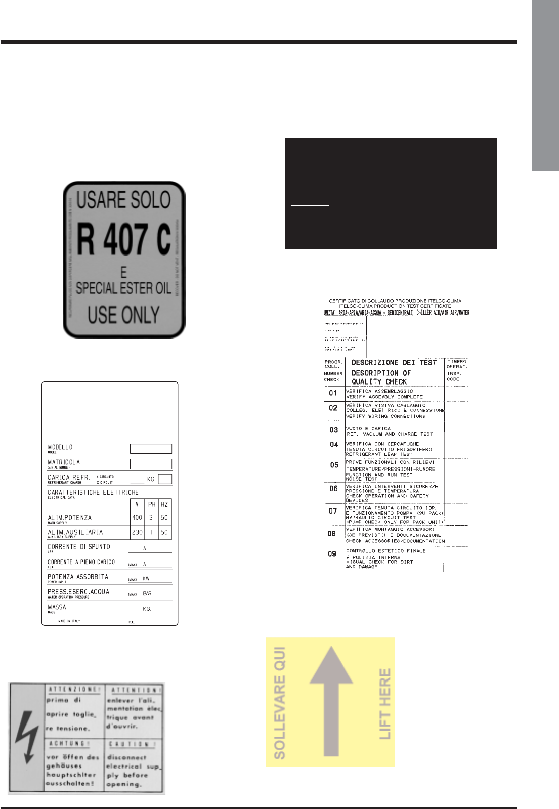
1.6 Safety Labels
The following labels are fitted to each unit in their
proper locations:
Compressor Oil Heater Warning Label
(Outside the door of the electrical panel)
Page 5
Refrigerant Identification Label
(Outside the panel door)
Electrical Warning Label
(Adjacent to the main switch)
Test Certificate
(Inside the door of the external panel)
Plate showing the lifting point
ATTENZIONE
INSERIRE LE RESISTENZE DI RISCALDAMENTO OLIO ALMENO
12 ORE PRIMA DI OGNI AVVIAMENTO.
PRIMA DELLA MESSA IN TENSIONE ASSICURARSI CHE LE VITI
DEI CIRCUITI ELETTRICI SIANO SERRATE COMPLETAMENTE.
WARNING
ENERGIZE THE CRANCKCASE HEATER FOR AT LEAST 12
HOURS BEFORE EACH STARTING.
BEFORE TIGHTENING-UP, TO TIGHTEN ALL TERMINAL SCREWS
ESPECIALLY THOSE IN MAIN CIRCUIT.
881000215/B
Unit Identification Label
(Inside the door of the external panel)

Manufacturer information
Page 6
1.7. Material Safety Data
Refrigerant Data
Safety Data
Toxicity
In contact with skin
In contact with eyes
Ingestion
Inhalation
Further Medical Advice
Long-term exposure
Occupational exposure limits
Stability
Conditions to avoid
Hazardous reactions
Hazardous decomposition products
General precautions
R407C
Low
Liquid splashes or sprays may cause freeze burns. Unlikely to be hazardous by skin absorption.
However, R407C may be slightly irritant and, if liquid, it has a strong degreasing effect. Flush conta-
minated skin areas with running water. If it comes into contact with wet fabrics, the liquid refrigerant
will cause them to freeze and adhere to the skin. Carefully remove the contaminated clothing since it
might adhere to the skin and cause freeze burns. Apply to a doctor if the affected skin areas should
be reddened or irritated.
Vapours have no effect. Liquid splashes or sprays may cause freeze burns. In these cases rinse your
eyes with running water or with a solution for eye lavages for at least 10 minutes. Immediately apply to
a doctor.
Very unlikely to occur. If this should be the case, it may cause freeze burns. Never induce vomit-
ing. Keep the patient awake. Make it rinse its mouth with running water and make it drink about
1/4 of a litre. Immediately apply to a doctor.
At high concentrations there is a danger of asphyxia due to a reduced oxygen content in the
atmosphere. In these cases take the patient to the open air, in a cool place and keep it at rest.
Administer oxygen, if required. Apply artificial respiration if breathing has ceased or if it has
become irregular. In case of heart failure immediately apply cardiac massage. Immediately
apply to a doctor.
A symptomatic and supportive therapy is generally suitable. A heart sensitisation has been
observed in some cases, as a result of exposures to particularly high concentrations. In the pres-
ence of catecholamines (such as for example adrenaline) in the blood flow, it has increased the
irregularity of the cardiac rhythm and then caused the heart failure.
Use in the presence of exposed flames, red heat surfaces and high humidity levels.
Possibility of violent reactions with sodium, potassium, barium and other alkaline substances.
Incompatible materials: magnesium and all the alloys containing over 2% of magnesium.
Avoid the inhalation of high concentrations of vapours. The concentration in the atmosphere
shall be kept at the minimum value and anyway below the occupational limits. Since vapours
are heavier than air and they tend to stagnate and to build up in closed areas, any opening for
ventilation shall be made at the lowest level.
R407C: A lifetime study which has been conducted on the effects inhalation may have on rats at
50,000 ppm has shown the onset of benign tumours of the testicle. These remarks suggest that
there is no danger for human beings if they are exposed to concentrations below the occupa-
tional limits or equal to them.
R407C: Recommended limits: 1,000 ppm v/v – 8 hours TWA.
R407C: Not specified.
R407 C: Halogen acids deriving from thermal decomposition and hydrolysis.
R407C: High concentration levels of its vapours in the air can produce an anaesthetic effect,
including the loss of consciousness. Particularly severe exposures may cause heart arrhythmia
and sometimes prove to be also fatal.

English
Manufacturer information
Page 7
Breathing protection
Storage
Preservation
Protection clothes
Behaviour in case of leaks or escapes
Disposal
Combustibility features
Behaviour in case of fire
Containers
In case of doubt about the actual concentration, wear breathing apparatus. It should be self-con-
tained and approved by the bodies for safety protection.
Refrigerant containers shall be stored in a cool place, away from fire risk, direct sunlight and all
heat sources, such as radiators. The maximum temperature shall never exceed 45°C in the stor-
age place.
Wear boots, safety gloves and glasses or masks for facial protection.
Never forget to wear protection clothes and breathing apparatus. Isolate the source of the leak-
age, provided that this operation may be performed in safety conditions. Any small quantity of
refrigerant which may have escaped in its liquid state may evaporate provided that the room is
well ventilated.In case of a large leakage, ventilate the room immediately. Stop the leakage with
sand, earth or any suitable absorbing material. Prevent the liquid refrigerant from flowing into
drains, sewers, foundations or absorbing wells since its vapours may create an asphyxiating at-
mosphere.
The best procedure involves recovery and recycle. If this is not possible, the refrigerant shall be
given to a plant which is well equipped to destroy and neutralise any acid and toxic by-product
which may derive from its disposal.
In case of fire wear protection clothes and self-contained breathing apparatus.
If they are exposed to the fire, they shall be constantly cooled down by water sprays.
Containers may explode if they are overheated.
R407C: Non flammable in the atmosphere.

Manufacturer information
Page 8
Lubricating Oil Data
Safety Data
Classification
In contact with skin
In contact with eyes
Ingestion
Inhalation
Conditions to avoid
Breathing protection
Protection clothes
Behaviour in case of leaks or escapes
Disposal
Behaviour in case of fire
Containers
Behaviour in case of fire
Oil
R407C: ICI EMKARATE RL32CF
MOBIL EAL ARTIC 22CC
Not dangerous.
Very little irritating. No first aid is required. it is enough to provide for a reasonable personal hy-
giene, i.e. washing the exposed skin areas with water and soap several times a day. Wash
dirty work clothes at least once a week.
Flush your eyes with a eyewash solution for at least 15 minutes and apply to a doctor.
Immediately apply to a doctor.
Immediately apply to a doctor.
Contact with strongly oxidising agents, alkaline or acid solutions as well as overheating. It may
degrade some types of paint and rubber.
It may only be used in well ventilated areas.
Always wear glasses or a mask for facial protection. Even if it is not strictly necessary, it is rec-
ommended to wear gloves in case of a long-term exposure.
Wear protection clothes and gloves. Stop the leakage. Absorb oil by using suitable substances,
such as sand, sawdust and any other material available on the market.
Oil and whatever may be contaminated by it shall be incinerated in a plant in compliance with
the local standards about the destruction of exhausted oils.
Use dry chemical compounds, carbon dioxide or extinguishing foams to put out the fire. The use
of water on hot oil which has been set on fire may cause splashing.
If oil has not caught fire yet, spray some water to disperse the vapours and protect the personnel
who are attempting to stop the leakage.
If they are exposed to the fire, they shall be constantly cooled down by water sprays.
In case of fire wear self-contained breathing apparatus.

English
Product Description
2 PRODUCT DESCRIPTION
2.1 General Information
AQL/AQH units are of an enbloc type with one sin-
gle refrigerating circuit. They are intended to cool
down the water required for any air-conditioning ap-
plication as well as any other fluid, such as for exam-
ple glycol water.
These units are completely assembled at works. They
are equipped with all the refrigerating connections
and the internal electrical wiring required for a rapid
installation on the field.
An operation test is performed after assembly, with
water flowing through the refrigerant/water ex-
changer in order to make sure that every refrigerat-
ing circuit is properly working. The refrigerating cir-
cuits of every unit are pressure tested before inspec-
tion, drained and charged with R407C.
A low noise level is the result of a careful study. It is
achieved on chillers by using technologically ad-
vanced components: SCROLL compressors with
soundproof cases and fans with streamline nozzles.
All this without negatively affecting the operation
performances and limits of the units.
AQL models can cool down chilled water at a tem-
perature between + 18 and + 5°C.
AQH heat pump models can warm up water at a
temperature between 25°C and 50°C.
Body and Frame
The base and frame of these units are made with
very thick galvanized steel elements, assembled with
stainless steel screws. All panels can be disassem-
bled to ensure easy access to internal components.
All galvanized steel parts are protected by epoxy
powder paint.
Compressors
The models are equipped with two SCROLL airtight
tandem compressors with an internal motor protec-
tion and a separate soundproof coverage.
The compressors of all models are assembled on rub-
ber shock absorbers. Their motors can be directly
started. They are cooled down by the aspirated re-
frigerant gas and equipped with internal thermistor
protections against overloads.
Overload protections are automatically reset after
having tripped. The compressor terminal box has an
IP54 protection degree (AQL/AQH 40-130).
Compressors are powered on and off by the micro-
processor of the unit control system which is intended
to control the delivery of the thermal refrigerating ca-
pacity.
Evaporators
Evaporators are made up of stainless steel plates.
They are thermally insulated by means of a thick flex-
ible insulating mattress with closed cells. The maxi-
Page 9

Product Description
mum operating pressures correspond to 10 bar for
the water side and to 30 bar for the refrigerant side.
Antifreeze protection for the water in the exchangers
is ensured by electrical heaters and differential pres-
sure switches for 30 units and by flow switches for
the other units. The water side of these exchangers is
connected by manifolds which will provide for the
connection to the plant by means of one single gas
threaded attachment.
Condensing batteries
The batteries forming the condenser are made up of
copper tubes arranged in staggered rows and me-
chanically expanded inside an aluminium finned
pack.
The maximum operating pressure on the refrigerant
side of the condensing batteries will correspond to
28 bar.
Condenser Fans
The condenser fans are of a helical type. They are di-
rectly coupled and have an impeller with wing con-
toured aluminium blades. Each fan is equipped with
a galvanised steel accident-prevention protection
which is painted after manufacture. The fans motors
are completely closed. They have an IP54 protection
degree and a protection thermostat embedded in the
windings.
Fans Control
All models have a step speed controller as a stan-
dard. It will act according to the condensing pres-
sure and allow the operation up to an external oper-
ation of –5/10°C
Refrigerating Circuits
Each unit is equipped with a single refrigerating cir-
cuit of external service valves intended to measure
the refrigerant pressure and charge, a sight glass
with a humidity indicator, a dryer filter and a thermal
expansion valve.
Refrigerating circuits are also complete with a high
pressure switch as well as a high and low transduc-
er.
Control Supply Panel
All components of the control system and those nec-
essary to start the motors are shop connected and
tested. In 40-130 models, the components of the con-
trol system and of the supply system are accessible
through separate doors, while in 20-25-30-35 mod-
els the board is protected by a door which can be re-
moved with a screwdriver. The control compartment
contains an electronic card and a control board with
keyboard and display, to show the operational func-
tions, as well as the intervention of the alarms and
the working blocks.
2.2 Accessories
Water Filter
In 20-35 units, the 1-1/2” filter is included in the sup-
plied equipment; in 40-130 units (in the model
equipped with a pump) the filter is positioned in the
hydraulic circuit, while in the models without pump it
is supplied as an optional.
Anti-Vibration Kit
For 20-35 units, the anti-vibration kit made of special
rubber is provided together with the unit. As for 40-
130 models, the kit includes 4 spring shock-ab-
sorbers, to be mounted during the installation of the
unit by the customer.
Electrical flow switch or Water Differential
Pressure Switch
Models 20-35: differential pressure switch.
Models 40-130: electrical flow switch.
Corrosion proofing protection
for condensing batteries
Two-level optional treatment
I) Simple treatment for a non extreme application
II) Treatment for an extreme blygold application.
Intrusion proofing protection
for condensing batteries
A galvanised and painted steel wire net protection is
assembled outside the unit.
Water Gauge
It is assembled on the unit as a standard.
Pump
Double pump kit (Mod. 40-130)
Standard pump with head >10m H
2
O
High Pressure Fans (high head)
For 40-130 units, channeled fans with static pressure
80 Pa (models 40-60) and 100 Pa (models 70-130).
3-Wire Supply Kit
For 40-80 units, 3-phase supply without neutral wire
(for 90-130 units, supply without standard neutral
wire).
Page 10

Low temperature kit –18 °C (40-130)
Phase Monitor Kit (40-130)
Kit for shipping by plane
Complete wooden package with a unit without re-
frigerant and with a nitrogen precharge.
No CE declaration is supplied by the manufacturer
in this case (the unit is entirely tested at works).
Hydro Module
The hydro module is available for the units with a
pump. It is installed beneath the unit through the pipe
fittings which are supplied with the unit.
The module is entirely enclosed in a RAL 9001 gal-
vanised and painted steel body. The tank is com-
pletely insulated with 30 Kg/m
3
closed cell polyethyl-
ene in a silver colour.
Antifreeze resistances or a heating booster kit are in-
stalled in the tank (upon request).
On/Off Remote Kit
It enables the operator to power on the unit when it is
in standby mode, to display alarms and to switch
over cooling – heat pump. The kit will include a 3
metre long cable for installation on the wall.i.
Sequencer kit - 4 units
Kit of external pressure gauge
Cooling mode
The low pressure liquid refrigerant will flow into the
evaporator where it is evaporated and overheated
by the heat absorbed from the chilled water flowing
through the plates.
The low pressure steam produced as a result of this
process will enter the compressor where it is over-
pressurised and overheated. After having left the
compressor, the high pressure steam will enter the
condensing battery which will absorb its heat and re-
lease it to air circulating outside.
After having been properly liquefied and subcooled,
the refrigerant will go through the expansion valve
where its pressure and temperature are reduced be-
fore flowing into the evaporator where the cycle will
start again.
Page 11
Product Description
English

Page 12
Product Description
2.3 Refrigeration Circuits
Units AQL 20-80
OIL EQUALIZER
Components:
1 Compressors C1/C2
2 Condenser
3 Dehydrating filter
4 Liquid lamp
5 Expansion valve
6 Plate-type exchanger
7 Safety valve (only for units 40-80)
Safety & Control Devices:
CPT High-pressure service outlet
DIS Outlet temperature probe
EPT Low-pressure service outlet
EWT Entering water temperature probe
FH1 Pressure switch
FPC Condensing pressure transducer
FPE Evaporation pressure transducer
LWT Leaving water temperature probe
P Differential pressure switch, water side (only for units 20-35)
FS Electrical flow switch (optional, for units 20-35)
WATER
COLLECTOR

Page 13
Product Description
English
WATER
COLLECTOR
OIL EQUALIZER
Units AQL 90-130
Safety & Control Devices:
CPT High-pressure service outlet
DIS Outlet temperature probe
EPT Low-pressure service outlet
EWT Entering water temperature probe
FH Pressure switch
FPC Condensing pressure transducer
FPE Evaporation pressure transducer
LWT Leaving water temperature probe
FS Electrical flow switch
Components:
1 Compressors C1/C2
2 Condenser
3 Dehydrating filter
4 Liquid lamp
5 Expansion valve
6 Plate-type exchanger
7 Silencer
8 Ball cock

Page 14
Product Description
WATER
COLLECTOR
OIL EQUALIZER
Components:
1 Compressors C1/C2
2 Air exchanger
3 Dehydrating filter
4 Liquid lamp
5 Thermostatic expansion valve
6 Plate-type exchanger
7 4-way valve
8 Liquid receiver
9 Check valve
10 Safety valve (only for units 40-80)
Safety & Control Devices:
CPT High-pressure service outlet
DIS Outlet temperature probe
EPT Low-pressure service outlet
EWT Entering water temperature probe
FH1 Pressure switch
FPC Condensing pressure transducer
FPE Evaporation pressure transducer
LWT Leaving water temperature probe
P Differential pressure switch, water side (only for units 20-35)
FS Electrical flow switch (optional, for unit 20-35)
Units AQH 20-80

Page 15
Product Description
English
Units AQH 90-130
WATER
COLLECTOR
OIL EQUALIZER
Safety & Control Devices:
CPT High-pressure service outlet
DIS Outlet temperature probe
EPT Low-pressure service outlet
EWT Entering water temperature probe
FH1 Pressure switch
FPC Condensing pressure transducer
FPE Evaporation pressure transducer
LWT Leaving water temperature probe
FS Electrical flow switch
Components:
1 Compressors C1/C2
2 Air exchanger
3 Dehydrating filter
4 Liquid lamp
5 Thermostatic expansion valve
6 Plate-type exchanger
7 4-way valve
8 Liquid receiver
9 Check valve
10 Silencer
11 Liquid storage
12 Ball cock

Page 16
Transportortion, Handling and Stockage
3 TRANSPORTATION, HANDLING
AND STORAGE
The AQL/AQH units are supplied fully assembled
and tested (except for the shock absorbers which are
separately supplied). They are ready to be installed
and started on the field.
R407C units are only charged with liquid refrigerant
and with oil in the quantity required for operation.
The low pressure side of the refrigerating
circuit on R407C units shall be charged by
means of the service valve arranged on the
thermal expansion valve before the device
is operated.
3.1 Inspection
The unit shall be immediately inspected upon receipt
to find out any damage since it has been delivered
ex works and transported at the customer’s risk. It is
also necessary to make sure that all the parcels spec-
ified on the delivery note have been delivered.
Any damage you may find out shall be immediately
reported in writing to the carrier. Even if the damage
is only on the surface, please notify our local repre-
sentative too.
The manufacturer disclaims all responsibility for the
shipment even if it has provided for its organisation.
3.2 Handling
The AQL/AQH units are designed to be lifted from
above, by means of cables and eyebolts. A spacer
shall be arranged between the cables in order to
prevent them from damaging the unit (see the figure
aside).
Before handling the devices, make sure the site you
have chosen for the installation can withstand its
weight and support its mechanical impact.
Avoid touching sharp parts (such as the fins of batter-
ies, for example) while handling the unit.
The unit shall never be placed on rollers.
Act as follows to lift and handle the unit:
h
Insert and secure the eyebolts into the frame holes
which have been marked on purpose.
h
Connect the cables to the eyebolts.
h
Insert the spacer between the cables.
h
Provide for hooking at the centre of gravity of the
device.
h
Cables shall have such a length that the angle they
form with the horizon when under tension is not
less than 45°.
Protect cabinet
during lifting
Space requirements
request to handling
Holes Ø 30 mm

Page 17
English
Transportortion, Handling and Stockage
While lifting and handling the unit, pay at-
tention. Otherwise, you might damage the
finned pack of the batteries arranged on
both sides of the unit. The sides of the unit
shall be protected by cardboard or ply-
wood sheets.
Until the unit is ready for operation, do not
remove the plastic envelope and the battery
protections which are intended to prevent
dirt, dust and any foreign matter from pene-
trating into the unit through the inlets of fans
or from damaging the external surfaces.
3.3 Storage
If the unit is to be stored before the installation for
some time, take at least the following precautions to
prevent damage, corrosion and/or deterioration:
h
Make sure all openings, such as for example wa-
ter connections, are well plugged and sealed.
h
Never store the units in a room where temperature
is above 42 °C (R407C units) or where the units
are directly exposed to the sunlight.
h
It is recommended to leave the finned batteries
covered to protect them against any risk of corro-
sion, especially if building works are still in
progress.
h
Store the units in areas where minimum activity is
likely to take place in order to avoid any risk of ac-
cidental damage.
h
Never use steam to clean the unit.
h
Remove all the keys required to have access to the
control panel and give them to the person in
charge of the field.
It is also recommended to provide for visual inspec-
tions at regular intervals.

Page 18
Installation
4 INSTALLATION
4.1 Installation Site
Before installing the unit, make
sure that the building structure
and/or the supporting surface can
withstand the weight of the device.
The weights of the units are de-
tailed by Chapter 9 of this manual.
These units have been designed to be installed on
the floor, in the open air. As a standard, they are
equipped with rubber vibration-damping supports
which shall be arranged in the middle, beneath the
supporting plates.
When the unit is to be installed on the ground, pro-
vide for a concrete bedplate which shall assure a
uniform distribution of the weights.
No special subbase is generally required. Howev-
er, if the unit is to be installed above inhabited
rooms, it is recommended to place it on spring
shock absorbers (40-130 units) which shall reduce
to a minimum the transmission of vibrations to the
structures.
When selecting the installation site, never forget to
consider as follows:
h
The longitudinal axis of the unit shall be parallel
to the direction of the prevailing winds so as to
assure a uniform air distribution on finned ex-
changers.
h
The unit shall never be installed in the proximity
of chimneys for the discharge of boiler flue gas-
es.
h
The unit shall never be installed downwind of
sources of grease contaminated air, such as for
example the outlets of large-kitchen extractors.
Otherwise, grease might build up on the fins of
refrigerant / air exchangers or condensers, act
as a fixing agent for any sort of atmospheric im-
purity and rapidly cause the exchangers to clog.
h
The unit shall never be installed in areas exposed
to heavy snowfalls.
h
The unit shall never be installed in areas exposed
to flooding or beneath drip stones, etc.
h
The unit shall never be installed in narrow inner
court yards or in any other restricted space
where the noise may be reflected by the walls or
where the air expelled by the fans may short-cir-
cuit on the refrigerant/air heat exchangers or
condensers.
h
The installation site shall be characterised by the
presence of the space required for air circulation
and for the performance of maintenance opera-
tions (see chapter 9 for further details).
4.2 Defrost Water Drainage
(only for AQH units)
When AQH units operate in the heat pump mode,
they will discharge water from the bedplate during
defrost cycles.
For this reason it is recommended to install these
units with a minimum ground clearance of 200 mm
to allow the defrost water to drain freely as well as
to prevent it from freezing and forming any ice
build-up.
AQH units shall be installed where defrost water
may cause no damage.

Page 19
Installation
English
4.3 Installation of Spring Shock
Absorbers
h
Prepare the bedplate which shall be smooth and
flat.
h
Lift the device and insert the shock absorbers. For
this purpose follow the instructions here below.
Installation of the vibration-damping sup-
port by means of a jack:
h
Fig. 1) Start assembling the components of the
jack.
h
Fig. 2) Insert the jack into the threaded seat
arranged on the upper plate of the vibration-
damping device. Insert the jack assembled on the
vibration-damping device into the hole arranged
on the bedplate of the machine.
h
Fig. 3) Make sure that the bedplate of the ma-
chine is arranged on the flat washer (pos. E) of
the jack. Use a wrench 13 and act on the high
nut (pos. D) (Fig. 3) to balance any difference in
height.
Use a grower washer (pos. F) and act on the low
nut (pos. C) to lock the position you have
reached.
At the end of the operation make sure the ma-
chine is elastic on the axes and ready for the in-
stallation of any vibration-damping balancing
joint in the water connections.
Fig. 1
Fig. 4
Fig. 3
Fig. 2
Insert

Page 20
Installation
4.4 External Water Circuit
The external water circuit shall guarantee
a constant water flow rate through the cir-
culating refrigerant/water heat exchanger
(evaporator) under steady operating condi-
tions and in case of a load variation.
The circuit shall be composed by the following ele-
ments:
h
A circulation pump which can ensure the neces-
sary flow rate and head.
h
The total content of the primary water circuit shall
never be lower than 2.5 lt/kW in terms of refrig-
erating capacity. If the total water volume in the
primary circuit should be unable to reach such a
value, an additional heat-insulated storage tank
should be installed. This tank is intended to avoid
any repetitive start of the compressor.
h
A membrane expansion tank complete with a
safety valve and a drain which shall be visible.
The expansion tank shall be dimensioned
in such a way that it can absorb a 2% ex-
pansion of the total volume of the water in
the plant (exchanger, pipelines, uses and
storage tank, if available). The expansion
tank shall never be insulated when the cir-
culating fluid is not flowing through it.
A differential pressure switch is mounted on 20-35
units as a standard. It will stop the unit whenever it
senses a load loss through the heat exchanger
which may result in a flow rate problem.
A flow switch is supplied for larger units as a stan-
dard.
In addition:
h
Install on/off valves on the lines at the inlet and
outlet of the manifolds of the exchangers (evapo-
rator).
h
Arrange a by-pass complete with an on/off valve
between the manifolds of the heat exchangers.
h
Arrange air vent valves at the high points of the
water lines.
h
Arrange drain points complete with plugs, clocks,
etc. in the proximity of the low points of the water
lines.
h
Insulate the water lines to prevent the heat from
blowing back into the unit.
Notes:
SF Mesh filter (supplied)
HR Antifreeze resistance of the plate-type exchanger
WPG Attachments for manometers (only on 40/130)
AP Vent valve
FV Water filling valve
PHE Plate-type exchanger
DU Drain cock
FC Flexible joints
FS Flow switch (only on 40/130)
PT Thermometric trap
PE Differential water pressure switch (only on 20/35)
EWC Attachment at the water inlet
LWC Attachment at the water outlet
CV On/Off valves
Version without a pump
PLANT COMPONENTS (NOT SUPPLIED) HYDRO KIT COMPONENTS

Page 21
Installation
English
Before filling the installation, remove any
impurity, such as sand, crushed stones and
welding scales, coating drops and any
other material which might damage the
evaporator.
It is advisable to flush with disposable water by-
passing the exchanger to avoid clogging.
The water used to fill the circuit shall be
treated in such as way that the pH will
have the correct value.
When two or several units are connected in paral-
lel, to balance the load losses of the various cir-
cuits, it is recommended to execute a “reverse re-
turn” connection (see the diagram below).
4.5 Water connections
The attachments at the water inlet and out-
let shall be connected in compliance with
the instructions which can be found on the
labels in the proximity of the attachments.
Connect the water lines of the plants with the at-
tachments of the unit whose diameters and positions
are shown by Chapter 9.
Notes:
SF Mesh filter (outside on 20/35)
ET Expansion tank
SV Safety valve
AP Vent valve
PHE Plate-type exchanger
PU Circulation pump
DU Drain cock
EAV Flow rate calibration valve (only on 40/130)
FS Flow switch (only on 40/130)
PT Thermometric trap
PE Differential water pressure switch (only on 20/35)
HR Antifreeze resistance of the plate-type exchanger
WPG Attachments for manometers (only on 40/130)
EWC Attachment at the water inlet
LWC Attachment at the water outlet
WI Water gauge
CV On/Off valves
FC Flexible joints
FV Water filling valve
Version with a pump
PLANT COMPONENTS (NOT SUPPLIED) HYDRO KIT COMPONENTS
UNIT 1
UNIT 2
Legend
S On/Off valves
VG Balancing valves

Page 22
Installation
4.6 Accumulation Tank Kit
The accumulation tank which has been designed for
mounting on AQL/AQH units is complete with all
the hydraulic and electrical components required
for the correct operation of the system.
These systems are carefully assembled and tested at
works. They are ready for operation after having
correctly realised all electrical and hydraulic con-
nections.
4.6.1 Features
20/35 units have one single tank whereas the units
starting from 40/50 have two tanks complete with
a standard connection. The kit will include an an-
tifreeze resistance, a drain cock, an automatic fill-
ing unit and an automatic air vent.
No pump is arranged on the kit since it is assumed
that the kit is meant for the units with a hydro option
where a pump and an expansion tank are already
available.
A tank arranged for mounting a heating booster re-
sistance kit may be optionally required (5 traps for
the kits from 20 to 50 and 8 traps for the kits for
larger sizes).
The tank is completely insulated with 30 Kg/m
3
closed cell polyethylene in a silver colour and en-
closed by a bearing structure made of passivated
and painted plates. The box is equipped with bulk-
heads which can be easily opened for internal in-
spection.
The kit is installed beneath the chiller. It is an inte-
gral part of the unit without changing the support
area.
Spring shock absorbers are also available for the
units starting from 40.
4.6.2 Supplied Material
The kits will be supplied with pipelines ready for in-
stallation. An antifreeze resistance with wiring, an
automatic water filling valve, a 3 bar safety valve,
a drain cock and a vent valve have already been
assembled.
Everything is placed on wooden pallets with wood-
en joists arranged on the kit for piling up and a film
for protection against atmospheric agents.
4.6.3 Operating Limits
The unit will guarantee the operation at an air tem-
perature of –10°C in a standard configuration with
one single antifreeze resistance.
4.6.4 Shock Absorbers
Shock absorbers are supplied for 20-35 sizes as a
standard. They shall be assembled by the customer
for 40-130 sizes during the installation.
IMPORTANT
Select the shock absorbers for the units with a hy-
dro kit.
4.6.5 Antifreeze Resistance
The antifreeze resistance of the tank (TEH) shall be
wired with the panel as it is shown by the diagram
attached to the unit.
4.6.6 Water Filter
The kit will use the water filter of the unit.
CAUTIONS
The unit + tank system shall be equipped with a fil-
ter for the 20-35 units. Use the filter + union as it is
shown by Figure 3.
Figure 3
Water filter
position
Positioning rubber shock absorbers
Figure 4
Positioning rubber
shock absorbers
Positioning rubber shock absorbers
Machines from 40 to 130

Page 23
Installation
English
4.6.7 Installation Procedure
The accumulation kits shall be arranged beneath
the unit. They will not change its overall dimensions
(Figure 3 and 4).
Arrange the rubber shock absorbers beneath the kit
before providing for its connection.
The installation of the spring shock ab-
sorbers will replace the installation of the
rubber shock absorbers supplied with the
accumulation kit.
Arrange the rubber shock absorbers between the
unit and the kit for the 40-130 units (Figure 4).
Tighten the screws into the holes arranged on the 4
corners in order to fasten the unit to the accumula-
tion kit.
Provide for the hydraulic and electrical connections.
In doing so, observe the diameters shown by the
quoted drawings.
The wiring for the standard antifreeze resistance is
arranged as it is shown by Figure 1 and 2 for the
different types of accumulation. The resistance is
connected with the main terminal box for the 20-25-
30-35 models and with the pull box arranged in the
fans department for larger sizes.
See the wiring diagram attached to the unit for the
correct execution of the electrical connections.
Install the water filter as it is shown by Figure 3 for
the machines of the 20-25-30-35 size.
Figure 1
Figure 2
Antifreeze
Resistance Wiring
Antifreeze
Resistance Wiring

Page 24
Installation
Storage Kit (112 l) for AQL/AQH 20-35 - Dimensional Data
Storage Kit (224/112 l) for AQL 40-50 / AQH 40 - Dimensional Data
SIDE VIEW
FRONT VIEW
TOP VIEW
NOTES:
A - WATER INLET ON THE PLANT SIDE Ø 1 1/2” GAS M
B - WATER OUTLET ON THE CHILLER SIDE Ø 1 1/2” GAS M
C - WATER FILLING Ø 1/2” GAS M
SIDE VIEW
FRONT VIEW
TOP VIEW
NOTES:
A - WATER INLET ON THE PLANT SIDE Ø 2” GAS M
B - WATER OUTLET ON THE CHILLER SIDE Ø 2” GAS M
C - WATER FILLING Ø 1/2” GAS M

Page 25
Installation
English
SIDE VIEW
FRONT VIEW
TOP VIEW
NOTES:
A - WATER INLET ON THE PLANT SIDE Ø 2” GAS M
B - WATER OUTLET ON THE CHILLER SIDE Ø 2” GAS M
C - WATER FILLING Ø 1/2” GAS M
Storage Kit (294/147 l) for AQL 60-80 / AQH 50-80 - Dimensional Data
FRONT VIEW
TOP VIEW
NOTES:
A - WATER INLET ON THE PLANT SIDE Ø 2” GAS M
B - WATER OUTLET ON THE CHILLER SIDE Ø 2” GAS M
C - WATER FILLING Ø 1/2” GAS M
Storage kit (294-147 l) for AQL/AQH 90-100 / AQH 90 - Dimensional Data
SIDE VIEW

Page 26
Installation
SIDE VIEW
FRONT VIEW
TOP VIEW
Storage Kit (294/147 l) for AQL/AQH 110-130 / AQH 100-130 - Dimensional Data
NOTES:
A - WATER INLET ON THE PLANT SIDE Ø 2” GAS M
B - WATER OUTLET ON THE CHILLER SIDE Ø 2” GAS M
C - WATER FILLING Ø 1/2” GAS M

Page 27
Installation
English
Page 27
4.7 Electrical Supply Features
Make sure the unit is not alive be-
fore acting on the electrical instal-
lation.
The unit shall be grounded.
The installer shall make sure that all the ex-
ternal connections of the unit have been re-
alised in compliance with the safety rules
in force.
The manufacturer is not responsible for
any damage and/or accident which may
result from the non observance of these
precautions.
The unit complies with the EN 60204-1 standard.
The following connections are required:
h
A pr=N three-phase line with earthing for the
power supply or without N for the units not re-
quiring it.
The electrical installation for distribution shall be
able to supply the power absorbed from the device
(see Chapter 9).
Disconnectors and magnetothermal switches shall
be dimensioned in such a way that they can handle
the pick-up current of the unit (see Chapter 9).
Power supply lines and insulation devices shall be
designed in such a way that every line is complete-
ly independent.
It is recommended to install the differential switches
which shall prevent any damage due to any phase
loss.
Fans and compressors are supplied by contactors
controlled by the control panel.
Each motor is complete with an internal safety ther-
mal switch as well as with external fuses or magne-
tothermal switches.
Power supply cables shall be run through the en-
trance passage which can be found on the front
side of the unit and then routed into the electrical
panel through the holes at its bottom.
4.8 Electrical Connections
The installation of the unit on the field
shall be carried out in compliance with the
Machinery Safety Directive (EEC 98/37),
the Low Voltage Directive (EEC 73/23), the
Electromagnetic Compatibility Directive
(EEC 89/336) as well as the usual proce-
dures and standards in force. The unit
shall never be operated if its installation is
not carried out according to the instruc-
tions above. The power supply lines shall
be composed by insulated copper wires
dimensioned for the maximum current
which may be absorbed.
Dimensioning shall be performed by con-
sidering the file length, the type of cable in
use, the type of installation as well as the
maximum operating room temperature.
Terminal connections shall be made according to
the connection diagram attached to this manual
and the wiring diagram supplied with the unit.
Before connecting the power supply lines,
make sure that the voltage value lies within
the limits shown by the Electrical Data in
Chapter 9.
Make sure that the unbalance between the phases
will not exceed 2% for three-phase systems. Check
by measuring the differences between the voltage
values of every single phase couple and their aver-
age value during the operation. The maximum per-
centage value of these differences (unbalance) shall
never exceed 2% of the average voltage.
If the unbalance should be unacceptable, contact
the Power Supply Company and require it to cor-
rect the fault.
If the unit is supplied by a line whose un-
balance is higher than the admitted value,
the warranty will automatically become
null and void.

Page 28
Installation
Electrical Connections of the AQL/AQH 20-35 units with Neutral
230Vac – AVAILABLE FOR ACCESSORIES
NOT PROTECTED
EXTERNAL FLOW SWITCH
EXTERNAL INTERLOCK
EXTERNAL PUMP APPROVAL
ALARMED UNIT + NO. SPTS
MAX 2,5 A @ 250 Vac
START/STOP REMOTE SWITCH
HEATING / COOLING SELECTION
NIGHT MODE OR DOUBLE SET POINT
SELECTION
FORCED LOAD SHEDDING
DISCONNECTOR
COMMON
HOT / COLD
TERMINAL BOARD ON THE MACHINE
USER CONNECTIONS
POWER LINE
400/ 3+N/50 – PE
SECTION
ELECTRONIC BOARD
PUMP CONTROL RELAY
TERMINAL 108 HYDRO KIT
TERMINAL 8 HYDRO KIT
TERMINAL 14 HYDRO KIT
TERMINAL 8 HYDRO KIT
TERMINALS ON THE MACHINE
TERMINALS FOR EXTERNAL
CONNECTIONS
NOTE: Always refer to the machine wiring diagram.
VOLTAGE FREE CONTACTS
ANTIFREEZE RESISTANCE CONTROL RELAY

Page 29
Installation
English
Page 29
Electrical Connections of the AQL/AQH 40-80 units with Neutral
ELECTRONIC BOARD
TERMINAL 108 HYDRO KIT
TERMINAL 8 HYDRO KIT
TERMINAL 14 HYDRO KIT
TERMINAL 8 HYDRO KIT
ANTIFREEZE RESISTANCE CONTROL RELAY
230Vac – AVAILABLE FOR ACCESSORIES
NOT PROTECTED
EXTERNAL FLOW SWITCH
EXTERNAL INTERLOCK
EXTERNAL PUMP APPROVAL
ALARMED UNIT + NO. SPTS
MAX 2,5 A @ 250 Vac
START/STOP REMOTE SWITCH
HEATING / COOLING SELECTION
NIGHT MODE OR DOUBLE SET POINT
SELECTION
FORCED LOAD SHEDDING
DISCONNECTOR
COMMON
HOT / COLD
TERMINAL BOARD ON THE MACHINE USER CONNECTIONS
POWER LINE
400/ 3+N/50 – PE
SECTION
PUMP CONTROL RELAY
TERMINALS ON THE MACHINE
TERMINALS FOR EXTERNAL
CONNECTIONS
NOTE: Always refer to the machine wiring diagram.
VOLTAGE FREE CONTACTS

Page 30
Installation
Electrical Connections of the AQL/AQH 40 - 80 units without Neutral
230Vac – AVAILABLE FOR ACCESSORIES
NOT PROTECTED
EXTERNAL FLOW SWITCH
EXTERNAL INTERLOCK
EXTERNAL PUMP APPROVAL
ALARMED UNIT + NO. SPTS
MAX 2,5 A @ 250 Vac
START/STOP REMOTE SWITCH
HEATING / COOLING SELECTION
NIGHT MODE OR DOUBLE SET POINT
SELECTION
FORCED LOAD SHEDDING
DISCONNECTOR
COMMON
HOT / COLD
TERMINAL BOARD ON THE MACHINE
USER CONNECTIONS
POWER LINE
400/ 3/50 – PE
SECTION
TERMINALS ON THE MACHINE
TERMINALS FOR EXTERNAL
CONNECTIONS
NOTE: Always refer to the machine wiring diagram.
VOLTAGE FREE CONTACTS
ELECTRONIC BOARD
PUMP CONTROL RELAY
TERMINAL 108 HYDRO KIT
TERMINAL 8 HYDRO KIT
TERMINAL 14 HYDRO KIT
TERMINAL 8 HYDRO KIT
ANTIFREEZE RESISTANCE CONTROL RELAY

Page 31
Installation
English
MORSETTIERA BORDO MACCHINA COLLEGAMENTI UTENTE
SEZIONATORE
LINEA POTENZA
400/3+N/50 + PE
ON/OFF
COMUNE
CALDO/FREDDO
MORSETTI A BORDO MACCHINA
CONTATTI PRIVI DI TENSIONE
NOTA: riferirsi sempre allo schema elettrico a bordo macchina
230Vac DISPONIB. PER ACCESSORI
MAX 40VA
INTERBLOCCO ESTERNO
CONSENSO POMPA ESTERNA
UNITA’ IN ALLARME - N.O. SPST
MAX 2.5A @ 250Vac
INTERRUTTORE REMOTO
DI MARCIA ARRESTO
SELEZIONE RISCALD/RAFFREDD.
SELEZIONE MODALITA’ NOTTE
O DOPPIO SETOPOINT
PARZIALIZZAZIONE FORZATA
DELLA CAPACITA’ FRIGORIFERA
MORS. 103 HYDROKIT
MORS. 8 HYDROKIT
MORS. 14 HYDROKIT
MORS. 8 HYDROKIT
RELE’ COMANDO POMPA
SCHEDA ELETTRONICA
RELE’ COMANDO RESISTENZA ANTIGELO
TERMINAL BOARD ON THE MACHINE USER CONNECTIONS
SECTION
POWER LINE
400/ 3/50 – PE
DISCONNECTOR
COMMON
HOT / COLD
TERMINALS ON THE MACHINE
TERMINALS FOR EXTERNAL
CONNECTIONS
VOLTAGE FREE CONTACTS
NOTE: Always refer to the machine wiring diagram.
230Vac – AVAILABLE FOR ACCESSORIES
NOT PROTECTED
EXTERNAL FLOW SWITCH
EXTERNAL INTERLOCK
EXTERNAL PUMP APPROVAL
ALARMED UNIT + NO. SPTS
MAX 2,5 A @ 250 Vac
START/STOP REMOTE SWITCH
HEATING / COOLING SELECTION
NIGHT MODE OR DOUBLE SET
POINT SELECTION
FORCED LOAD SHEDDING
TERMINAL 103 HYDRO KIT
TERMINAL 8 HYDRO KIT
TERMINAL 14 HYDRO KIT
TERMINAL 8 HYDRO KIT
PUMP CONTROL RELAY
ELECTRONIC BOARD
ANTIFREEZE RESISTANCE CONTROL RELAY
Electrical Connections of the AQL/AQH 90 - 130 units without Neutral

Page 32
Commissioning
5 COMMISSIONING
The unit may only be started by the person-
nel trained by an authorised Itelco-Clima
Service Centre. Otherwise, the warranty
will be automatically made null and void.
The operations performed by the technical
service personnel are limited to the start-up
of the unit. They do not include any other
work on the installation, such as for exam-
ple the execution of electrical, hydraulic
connections, etc. All the other operations
preparatory to the start-up, including oil
pre-heating for at least 12 hours, shall be
carried out by the Installer.
5.1 Preliminary Checks
The following operations shall be performed before
the arrival of the Itelco-Clima personnel on site in
order to start up the unit.
h
Check the sections of supply cables, the ground
connection, the clamps of terminals and the good
operation of contactors when the main discon-
nector is open.
h
Make sure the R.S.T. phase sequence is correct.
h
Make sure the unbalance between the supply line
phases is within the limits as per Chapter 4.
h
Connect (without any supply) the flow switch con-
tacts, the pump thermal overload cut-out or any
other device to terminals 1-2 and 3-4.
h
Make sure the components of the water circuit
connected to the circulation refrigerant / fluid ex-
changer (pumps, sensors, uses, expansion tank
and storage tank, if any) are correctly installed in
compliance with the instructions of the manufac-
turers.
h
Make sure that the water circuits have been filled
and the circulation of the various fluids occurs
correctly, without any sign of leakage or air bub-
bles. If ethylene glycol is used as an antifreeze,
make sure its mixture percentage is correct.
h
Make sure that the direction of rotation of the
pumps is correct and the fluids have circulated
for at least 12 hours for each pump. Clean the
baskets of the filters on the aspirating side of the
pumps.
h
Calibrate the installation so that the fluid will
have the specified flow rate.
h
Make sure the quality of the circulating fluid com-
plies with the specifications.
h
Make sure oil electrical heaters have been ener-
gised for at least 12 hours.
5.2 Starting
The starting sequence shall be performed as fol-
lows:
h
Close the main disconnector (at least 12 hours
before).
h
Make sure that the oil inside the compressors is
hot enough (the external temperature of the oil
pan shall be at least 40 °C) and the auxiliary cir-
cuit of controls is energised.
h
Make sure that the whole external equipment is
perfectly working and the control devices of the
installation are properly calibrated.
h
Start the pumps of the circulating fluids and make
sure they can deliver the flow rate required.
h
Set the fluid temperature you wish on the control
panel (refer to Chapter 6).
h
Start the unit you wish (refer to Chapter 6).
h
Check the direction of rotation of scroll compres-
sors.
h
After about 15 minutes make sure no gas bubble
is visible through the sight glass of the liquid line.
If air bubbles are visible through the sight
glass, it means that the unit has lost part of
its charge through one or several leakage
points. The leaks shall be removed. Refer
to Chapter 7.
h
Repeat the starting procedure after having re-
moved the leaks.
h
Make sure the oil level is correct.
MAX
MIN

Page 33
English
Commissioning
5.3 Performance Check
Check as follows:
h
The inlet temperature of the fluid circulating in the
manifold of the exchangers.
h
The outlet temperature of the fluid circulating in
the manifold of the exchangers.
h
The flow rate of the fluid through the exchangers.
h
The current absorbed by compressors and fans at
the start-up and under steady operating condi-
tions.
Check the saturated evaporation and condensation
temperatures during the unit operation by connect-
ing the manometers with the two Schraeder valves
which can be found on the low and high pressure
side of refrigerating circuits.
5.4 Delivery to the User
h
Inform the user about the instructions for use
which can be found in Chapter 6.
High
pressure side
Low pressure
side
15-18°C above the air inlet temperature in
the battery.
5-7°C below the outlet temperature of the
water circulating from the evaporator.

Page 34
AQL/AQH Control
^ SWITCH
makes it possible to vertically scroll through the
MENUS and SUB-MENUS and to increase the nu-
merical value of the parameters.
TEST SWITCH
Starts an automatic testing procedure for all the main
functions of the unit. See TESTING PROCEDURE.
6 AQL/AQH CONTROL
6.1 Electronic Card Control
h
Keyboard
Display
SM1 Switch
TEST
Machine ON
SM1 SWITCH:
– position 0: machine OFF. The resistors may be en-
abled. Test available.
– position 1: machine ON. Test available.
> SWITCH
makes it possible to horizontally scroll through the
MENUS and to display the parameter values

Page 35
English
AQL/AQH Control ERRATA CORRIGE
DIP OFF ON STANDARD
1 Pump ON only if the unit is ON Pump always ON OFF
2 Step ventilation Continuous ventilation OFF
3 Pump Off in antifreeze protection Pump On in antifreeze protection ON
4 Discharge of comp. 1 Discharge of comp. 2 OFF
5 Normal Slave OFF
6 Room temperature compensation No compensation ON
7 Enable input 5 pump’ thermal switch Disable input 5 pack unit = OFF
non pack = ON
8 Forced defrosting OFF Forced defrosting ON OFF
9 Serial address OFF
10 Serial address OFF
11 Serial address OFF
12 Serial address OFF
Display keys
Display menus
Display keys
Display menus
cool
6.2 Dip Switches
The control is provided with 2 DIP switch blocks:
DSW1 (12 dips) and DSW2 (8 dips).
FUNCTION OF DSW1 DIPS
h
Display keys
All th information is displayed on 4 displays (7-seg-
ments).
Use the > and ^ keys to enter the display menus as
follows:

Page 36
AQL/AQH Control

Page 37
English
AQL/AQH Control
6.3 ALAr and LOg Menus
The activated alarms of the unit are displayed in the
ALAr menu. More alarms can be activated at the
same time. The alarms are recorded in a permanent
LOG memory.
Code Alarm description Auto Manual Notes
ADC Microprocessor error
CPF failure of HP transducer, off scale
EPF failure of LP transducer, off scale
REF refrigerant leak - low pressure
CPnc failure of HP transducer, unchanged pressure
EPnc failure of LP transducer, unchanged pressure
CFC1 failure of compressor 1 wrong rotation
CFC2 failure of compressor 2 wrong rotation
EWTH failure of return water probe short-circuit
EWTL failure of return water probe not connected
LWTC no variation in the leaving water temperature
LWTH failure of leaving water probe short-circuit
LWTL failure of leaving water probe not connected
LWLH failure of compressor discharge temperature probe short-circuit
DISL failure of compressor discharge temperature probe not connected
OATH failure of air temperature probe short-circuit
OATL failure of air temperature probe not connected
OC1L failure of temperature probe - coil 1 not connected
OC2L failure of temperature probe - coil 2 not connected
HPP first high pressure protection stop1 compressor
HP high pressure protection from transducer
auto energized 3 times
HPC high pressure protection - locked circuit
LP low pressure protection
DIS excessive discharge temperature of compressors
LO insufficient leaving water temperature
HI excessive entering water temperature
FS electrical flow switch or water differential pressure switch
CF1 thermal protection, compressor 1
CF2 thermal protection, compressor 2
OF1 thermal protection, fans
PF thermal protection, pump
LOu low water volume
EEP microprocessor error
JUMP wrong DIP configuration DIP check
ConF wrong configuration
•
•
•
•
•
•
•
•
•
•
•
•
•
•
•
•
•
•
•
•
•
•
•
•
•
•
•
•
•
•
•
•
•
•
The last 10 recorded alarms are displayed in the
LOg menu. The following table shows the alarm
codes and description:
6.4 SEnS Menu – Sensors reading
Displayed Code Meaning
EWT entering water temp
LWT leaving water temp
CP discharge pressure
EP intake pressure
CPS sat. temperature (discharge)
EPS sat. temperature (intake)
Dis compressor’s discharge temp
OAT room air temp
OCT 1 probe temperature in coil 1
OCT 2 probe temperature in coil 2

Page 38
Maintenance
Check the temperature of the fluid
leaving the exchanger
Check any exchanger load loss
Check the electrical absorption
Check the suction temperature and
pressure
Check the delivery temperature and
pressure
Check the compressor oil level
Make sure there is no gas bubble in
the liquid line
Make sure the finned pack of the
external battery is clean
Check the operation of the oil
heater
Check the operation of the Remote
Control Unit
Check the operation of the high
pressure switch
Check the insulation of the
circulating refrigerant / fluid
exchanger
Make sure the screws of terminals
are firmly tight
Clean the external surfaces of the
unit with soapy water
Check the operation of the
differential pressure switch
Check the density of the antifreeze
mixture (glycol water) if this mixture
is used
Drain and clean the circulating
refrigerant / fluid exchangers
7 MAINTENANCE
While discharging the refrigerating
circuits, never release the refriger-
ant into the atmosphere. Use prop-
er recovery equipment for the dis-
charge. If the recovered refrigerant
can not be reused, it shall be re-
turned to the producer.
Never dispose of the compressor oil
in the atmosphere since it contains
dissolved refrigerant. If used, the oil
shall be returned to the producer.
The Safety Section of this manual shall be
carefully read before performing any
maintenance operation on the unit.
Unless otherwise specified, the maintenance opera-
tions here below can be performed by any mainte-
nance technician who has been specifically trained.
7.1 General Information
Itelco-Clima AQL/AQH units have been designed
for constant operation, provided that they are regu-
larly serviced and operated within the limits speci-
fied by this manual. Every unit shall be serviced ac-
cording to a User / Customer schedule and regularly
inspected by the personnel from an authorised Itelco-
Clima Service Centre.
It is the User’s responsibility to fulfil these mainte-
nance requirements and/or make an agreement
with an Itelco-Clima Service Centre so as to protect
the operation of the device.
If any damage or failure should occur as a result of
improper maintenance during the warranty period,
Itelco-Clima will not be liable for any cost required to
restore the original state of the device.
This section is only applicable for basic AQL/AQH
units. According to the circumstances, it might be
supplemented with additional instructions as a result
of any change which may be made to the unit or to
the use of the ancillary equipment.
7.2 Daily Maintenance
Maintenance checks shall be performed by a com-
petent person according to the schedule here
below.
Operations
Daily
Weekly
Monthly
Season start
Season end
•
•
•
•
•
•
•
•
•
•
•
•
•
•
•
••
•
However, it shall be noted that AQL/AQH units can
not be directly repaired by the User who shall refrain
from attempting to repair any failure which may be
discovered during daily maintenance. In case of
doubt, contact the Itelco-Clima Service Centre.
Scheduled Maintenance

Page 39
English
Maintenance
7.3 Refrigerant Charge
AQL/AQH units operating with R407C
shall be exclusively charged with refriger-
ant in the liquid state to prevent the refriger-
ant composition from altering. A service
valve is arranged for charging the unit at
low pressure.
If the charge is not enough, the unit will reduce its
performance. In extreme cases, the low pressure
switch might trip and cause the unit to stop.
If the charge is too large, the condensation pressure
might increase to such an extent that it might cause
the high pressure switch to trip and the unit to stop.
The compressors of the unit shall never be
used as vacuum pumps to discharge the
corresponding circuits.
The refrigerating circuit shall be recharged whenev-
er it has been discharged for maintenance purposes
(elimination of leaks, compressor repair, etc.).
Charge quantities are specified by Chapter 9.
Before being charged, every circuit shall be dried
and vacuum-purged so that the absolute pressure
may not exceed 50 Pa inside it.
7.4 Compressors
Compressors are supplied with the oil quantity re-
quired for operation. This charge should last as long
as the compressor under normal operating condi-
tions. The lubricant shall not be topped up as long as
the refrigerating circuit is operating correctly and un-
til no repair has been carried out.
If a compressor is faulty and it is to be replaced, re-
placement may be only carried out by the personnel
of an Authorised Service Centre.
7.5 Refrigerant/Air Exchangers
They are made up of copper tubes and aluminium
fins. If the refrigerant should leak as a result of an ac-
cidental damage, repair operations may be only car-
ried out by the personnel of an Authorised Service
Centre.
To make service and maintenance operations easier,
the external surfaces of these exchangers shall al-
ways be kept free of any impurity, such as leaves, fi-
bres, insects, etc. If heat exchangers are dirty, the
power absorbed may increase. This may also cause
the unit to reach such a pressure threshold which
might trigger an alarm and cause the unit to stop.
Avoid damaging the aluminium finned
pack during cleaning.
The internal side of the finned pack of these ex-
changers can be cleaned by compressed air orient-
ed parallel to the finned pack and in a direction op-
posite to that of the normal air circulation. The exter-
nal side can be cleaned by a vacuum cleaner. The
finned pack of these exchangers can be also
cleaned by spraying a water and soap solution.
7.6 Fans of the Refrigerant/Air
Exchangers
Each fan has got an impeller with wing contoured
blades and a cylindrical conveyor. The bearings of
the motors are life lubricated for life.
7.7 Dryer Filter
Refrigerating circuits are complete with dryer filters.
These filters can not be inspected and they are com-
plete with a mechanical filter. When the dryer filter is
clogged, this is shown by the presence of gas bub-
bles in the sight glass and by a temperature differ-
ence between the side upstream and downstream
the filter.
If the presence of gas bubbles should persist after the
filter cartridge has been replaced, it means that the
unit has lost part of the refrigerant charge through
one or more leaks which shall be identified and re-
paired.

Page 40
Maintenance
7.8 Sight Glass
The sight glass is used to observe the liquid refriger-
ant flow and to find out if there is some humidity in-
side it. If there are some gas bubbles in the liquid
flow, it means that the dryer filter is clogged or that
the refrigerant charge has partially leaked out.
A coloured indicator is arranged inside the sight
glass. If you compare its colour with the chromatic
scale arranged on the external ring of the sight
glass, you may find out if there is some humidity in
the refrigerant. If the humidity content should be too
high:
h
Discharge the circuit and collect the refrigerant.
The circuit shall be then vacuum-purged and
recharged.
7.9 Thermal Expansion Valves
The refrigerating circuits of the AQL/AQH units are
equipped with a thermal expansion valve complete
with an external equaliser. This valve is calibrated at
works to ensure 5 K overheating.
Act as follows to control overheating:
Read the suction pressure by using a manometer
connected with the filling valve on the suction side.
Use the thermometric scale of the manometer to iden-
tify the Tsa saturated temperature corresponding to
the pressure you have measured.
Measure the Tse effective suction temperature by us-
ing a contact thermometer arranged on the attach-
ment at the outlet of the evaporator gas.
Overheating is calculated as follows:
S = Tse – Tsa
Or use the Menu function
Overheating can be changed by acting on the cali-
brating screw of the thermal expansion valve. Turn
this screw clockwise to increase overheating. Turn it
counterclockwise to decrease overheating.
The valve shall be calibrated again by turning the
calibrating screw by one revolution at a time and
then by operating the unit for 5 minutes. After this pe-
riod of time has elapsed, check overheating and cor-
rect it again, if required.
The thermal expansion valves of the AQH
models shall be calibrated with the utmost
care since every circuit of these units has
got one single thermal expansion valve
which is used both in cooling and in heat-
ing mode.
If the thermal expansion valve can not react to the
overheating calibration, it means that it is not operat-
ing correctly and that it shall be replaced. The ther-
mal expansion valve may be only replaced by an
Authorised Service Centre.
7.10 Refrigerant / Circulating Fluid
Exchanger
The cleanness of these exchangers on the water side
shall be checked at regular intervals. This can be ac-
complished by checking the load loss on the water
side (see Chapter 9) or by checking the difference
between the incoming and outgoing fluid tempera-
ture and by comparing these values with the evapo-
ration temperature.
The difference between the outgoing fluid tempera-
ture and the evaporation temperature shall lie be-
tween 5 and 7 K to enable the heat exchange to oc-
cur optimally. A greater difference means that the ex-
changer is not working optimally since it is dirty.
In these cases, this exchanger shall be chemically
cleaned by the personnel authorised by the manufac-
turer.
Contact an Authorised Service Centre for any other
type of operation (extraordinary maintenance, re-
placement of the whole exchanger, etc.).
Contact an Authorised Service Centre for any other
type of service (extraordinary maintenance, replace-
ment of heat exchangers, etc.).

Page 41
English
Trouble Shooting
8 TROUBLE SHOOTING
The following table will give a detailed list of unit faults and remedies. Contact an Authorised Itelco-Clima
Service Centre for any other problem which can not be clearly ascribed to one of the cases listed in the table
and/or for any other need for technical assistance.
Fault
The unit operates continuous-
ly, but without cooling.
Hoar-frost is building on the
suction line.
The noise level is too high.
The compressor oil level has
decreased.
One or two compressors are
not working.
Low refrigerant charge.
The dryer filter is clogged.
Loss of efficiency in one or both circuits.
The thermal expansion valve is out of calibra-
tion.
Vibrating pipelines.
The thermal expansion valve is whistling.
Noisy compressor.
One or more than one oil or gas leaks from
the circuit.
The compressor is mechanically damaged.
Faulty oil heater.
Power supply interruption.
The high pressure switch has tripped.
The control circuit fuse has tripped.
Loose terminals.
The thermal switches intended to protect the
power supply have tripped.
Wrong electrical connections.
The line voltage is too low.
The compressor motor has short-circuited.
The compressor has seized.
Check the fuses of the control circuit and make sure the circuit
is neither grounded nor short-circuited. Replace the fuses, if
required.
Tighten the terminals.
Make sure the safety and control devices are properly work-
ing. Identify and eliminate what has caused the trip.
Check the electrical connections of the control and safety de-
vices.
Check the line voltage. Remove the problem if it is due to the
plant. Contact the power supply company if it is due to the
network.
Check the continuity of the motor windings.
Replace the compressor.
Top up the refrigerant charge.
Replace the dryer filter.
Check the compressor and replace it, if required.
Increase overheating.
Check the charge.
Secure the pipelines.
Check the anchorage of the pipelines.
Top up the charge.
Check the dryer filter and replace it, if required.
Check the state of the valves.
The bearings have seized: replace the compressor.
Make sure that the nuts intended to anchor the compressor
have been firmly tightened.
Identify and eliminate all leaks.
Contact an Itelco-Clima Authorised Service Centre.
Make sure the electrical circuit and the elements of the electri-
cal heater are properly working. Replace any defective com-
ponent.
Check the fuses of the supply circuit and make sure the circuit
is neither grounded nor short-circuited.
Reset the pressure switch from the panel and restart the unit.
Identify and eliminate what has caused the high pressure
switch to trip.
Probable Cause Remedy

Page 42
Trouble Shooting
Fault
Low pressure alarm. The unit
stops.
The high pressure switch has
tripped. The unit stops.
The liquid line is too high.
The liquid line is covered
with hoar-frost.
The fans can not rotate.
The thermal refrigerating
power has decreased.
The heater of the refrigerant
/ circulating fluid is not
working.
The temperature of the circu-
lating fluid is poorly checked
or not checked at all.
The fluid is only poorly
circulating.
The unit is not working
and the low flow rate
alarm has tripped.
The refrigerant is leaking.
Low charge.
Faulty pressure switch.
The pressure switch is malfunctioning.
The delivery valve is partially closed.
There are non condensables in the circuit.
The fans of the refrigerant/air exchanger are
not working.
Low charge.
The valve of the liquid line is partially closed.
The dryer filter is clogged.
Problems in the electrical circuit.
The internal thermal switches have tripped.
Faulty compressor.
The air/refrigerant exchanger is clogged.
Low charge.
The connection threshold is out of calibration.
The heater circuit has been interrupted.
The control thermostat is out of calibration.
The fluid thermal head is wrong.
The electronic control system is malfunction-
ing.
Air in the hydraulic circuit.
Deposits or impurities in the refrigerant / cir-
culating fluid exchanger
No circulation
The flow switch is not working.
The differential pressure switch is not work-
ing.
The fluid side of the exchanger is dirty.
Identify and eliminate the leakage.
Top up the charge.
Replace the pressure switch.
Check the pressure switch and replace it, if required.
Open the valve completely and replace it, if required.
Discharge the circuit.
Check the motors and the connections. Repair and/or re-
place, where required.
Identify and eliminate what has caused the charge to de-
crease.
Check the opening of the valve.
Replace the filter cartridge.
Check all connections.
Contact an Itelco-Clima Authorised Service Centre.
Contact an Itelco-Clima Authorised Service Centre.
Clean the exchanger and the circuit chemically.
Clean the batteries of the exchanger.
Top up the charge.
Check the calibration on the control panel.
Check the heater and replace it, if required.
Check the calibration on the control panel.
Check the fluid flow rate and content.
Contact an Itelco-Clima Authorised Service Centre.
Use the vent valves to discharge air.
Backwash the exchanger.
Check the pumps.
Make sure the flow switch is properly working.
Make sure the differential pressure switch is properly working.
Probable Cause Remedy

Page 43
English
Technical Data
9 TECHNICAL DATA
9.1 Hydraulic Features
AQL/AQH Unit
Useful head AQL/AQH 20-25-30-35
Useful head AQL/AQH 40-80

Page 44
Technical Data
AQL / AQH 20-25-30-35 Refrigerant - Water Heat Exchangers Pressure Drops
AQL / AQH 90-130 Standard Water Pump Available Head
0
20
40
60
80
100
120
140
160
180
200
234567891011
130
120
110
100
90
Dp(kPa)
(l/s)
water side
pressure drops
water flow

Page 45
English
Technical Data
AQL / AQH 40-80 Refrigerant - Water Heat Exchangers Pressure Drops
1
10
100
1000
2345678910
90
100
110
120
130
AQL / AQH 90-130 Refrigerant - Water Heat Exchangers Pressure Drops
pressure drops
Dp(kPa)
(l/s)
water flow
water flow
pressure drops

Page 46
Technical DataTechnical DataTechnical Data
9.2 Working Range
Units AQL / AQH 20 -130 (R407C)
Working Range in cooling mode Working Range in heating mode
Water temperature Min. Max
inlet on start-up °C 10 30
inlet under nominal conditions °C 8 23
outlet under nominal conditions °C 5 18
delta T °C 3 7
standard fans Pa 0
high discarge head fans Pa
80 (mod. 40-60) 100 (mod. 70-130)
minimum water content
L/kW 2,5
Air temperature °C -10 46
Water temperature Min. Max
inlet on start-up °C 18 -
inlet under nominal conditions °C 20 45
outlet under nominal conditions °C 23 50
delta T °C 3 7
standard fans Pa 0
high discarge head fans Pa
80 (mod. 40-60) 100 (mod. 70-130)
minimum water content
L/kW 2,5
Air temperature °C -5 20
Leavig water temperature (°C) Leavig water temperature (°C)
Air temperature (°C)
Air temperature (°C)

Page 47
English
Technical Data
9.4 Noise Levels
Sound Power Levels - Lw(A) dB(A)
Sound Pressure Levels - Lp(A) dB(A)
Sound pressure levels at 1 m distance, according to ISO 3744.
* Sound levels applicable to all high discharge head units (90-130).
9.3 Safety Devices
Italiano
Models 20 25 30 35 40 50 60 70 80 90 100 110 120 130
Fans heat protection yes
Compressors heat protection yes
Magnetothermal switch auxiliary / fan
yes
Compressors magnetothermal switch
yes
Differential water pressure switch
yes
Water flow switch yes
High pressure switch yes
Exchanger antifreeze resistance
yes
High pressure transducer yes
Low pressure transducer yes
Sound
Power
Level dB(A)
Model
Octave Band Central Frequency (Hz)
63 125 250 500 1000 2000 4000 8000
AQL/AQH 20 55 63 67 73 64 62 60 57 75
AQL/AQH 25 56 64 68 74 65 63 61 58 76
AQL/AQH 30 56 64 68 74 65 63 61 58 76
AQL/AQH 35 57 65 69 75 66 64 62 59 77
AQL/AQH 40 62 70 74 80 74 70 67 64 82
AQL/AQH 50 62 70 74 80 74 70 67 64 82
AQL/AQH 60 63 71 75 82 75 71 68 65 84
AQL/AQH70 67 75 79 84 75 74 72 69 87
AQL/AQH80 67 80 84 84 75 79 77 74 87
AQL90/AQH90 80 79 73 79 80 76 71 61 86
AQL100 80 79 73 79 80 76 71 61 86
AQH100 81 81 74 80 80 78 73 61 87
AQL110/AQH110
81 81 74 80 80 78 73 61 87
AQL120/AQH120
81 81 74 80 80 78 73 61 87
AQL130/AQH130*
86 86 79 85 85 83 83 67 93
Sound
Power
Level dB(A)
Model
Octave Band Central Frequency (Hz)
63 125 250 500 1000 2000 4000 8000
AQL/AQH 20 39 47 51 57 48 46 44 41 59
AQL/AQH 25 40 48 52 58 49 47 45 42 60
AQL/AQH 30 40 48 52 58 49 47 45 42 60
AQL/AQH 35 41 49 53 59 50 48 46 43 61
AQL/AQH 40 46 54 58 64 58 54 51 48 67
AQL/AQH 50 46 54 58 64 58 54 51 48 67
AQL/AQH 60 47 55 59 65 58 54 52 48 67
AQL/AQH70 51 59 63 68 59 58 56 53 70
AQL/AQH80 51 64 68 68 59 63 61 58 70
AQL90/AQH90 63 62 56 62 63 59 54 44 69
AQL100 63 62 56 62 63 59 54 44 69
AQH100 63 63 56 61 61 60 55 43 69
AQL110/AQH110
63 63 56 61 61 60 55 43 69
AQL120/AQH120
63 63 56 61 61 60 55 43 69
AQL130/AQH130
68 68 61 67 67 65 65 49 75

Page 48
Technical DataTechnical DataTechnical Data
9.5 General Characteristics
Units AQL/AQH 20-80
Models 20 25 30 35 40 50 60 70 80
Cooling Capacity* AQL kW 21,5 26,0 29,9 34,2 39,5 47,9 55,9 67,0 75,0
Power absorbed by Compressors AQL (1)
kW 7 8,6 10 10,8 14,4 17,6 21,7 25,0 27,6
Cooling Capacity* AQH kW 21,5 26,0 29,9 34,2 39,4 47,9 55,9 67,0 75,0
Power absorbed by Compressors AQH (1)
kW 7 8,6 10 10,8 14,4 17,6 21,7 25,0 27,6
Heating Capacity* AQH
kW 23,1 28 32,9 37,4 45,0 56,0 65,0 78,0 84,9
Power absorbed by Compr. in Heat Pump (1)
kW 7,2 8,6 10 10 14,5 17,6 22,0 25,5 28,5
Number of Refrigeration Circuits No. 111111111
Capacity Steps
No.222222222
Supply Volt 400/3/50
Refrigerant R407C
Refrigerant Charge kg 6,4 6,4 6,4 7,6 9 11,5 13 14 16
Type of Start-up Direct
Type Scroll
Quantity No. 222222222
Type Plate
Number
No.111111111
Water Flow rate l/s 1,0 1,2 1,4 1,6 2 2,2 2,7 3,2 3.6
Pressure Drop, Water Side kPa 37 36 29,5 38,5 30 25 30 26 31,5
Type gas thread
Inlet diameter inch 1”1/2 1”1/2 1”1/2 1”1/2 2” 2” 2” 2” 2”
Outlet diameter inch 1”1/2 1”1/2 1”1/2 1”1/2 2” 2” 2” 2” 2”
* Water 12°C / 7°C, room temperature 35°C (cooling)
Water 40°C / 45°C, room temperature 7°C BS-6°C BU (heating)
(1) Maximum absorbed power calculated as the sum of the maximum power absorbed by compressors and the maximum power absorbed by
fans.
(2) The pressure refers to 1 meter in free field, ISO Standard.
Compressors
Evaporators
Quantity
No.
222211111
Max. air flow rate (high) m
3
/s 3,1 3,1 3,1 3,1 4,3 4,3 4,3 4,3 5,8
Absorbed power kW 0,3 0,3 0,3 0,3 1,1 1,1 1,1 2 2
Fans
Hydraulic Connections
Number No. 111111111
Absorbed power kW ---------
Pump
Shipping weight without pump kg 265 275 285 290 450 550 550 580 600
Working weight kg 280 290 300 305 475 550 570 600 620
Weights
Lenght mm 1477 1477 1477 1477 1719 1719 2150 2150 2150
Width mm 516 516 516 516 1200 1200 1200 1200 1200
Height mm 1607 1607 1607 1607 1634 1634 1634 1634 1634
Dimensions
Sound Power Level dB(A) 75 76 76 77 82 82 84 87 87
Sound Pressure Level (2) dB(A) 59 60 60 61 67 67 67 71 71
Acoustical data

Page 49
English
Technical DataTechnical DataTechnical Data
Models 90 100 110 120 130
Cooling Capacity* AQL
kW 86,4 98,0 112,0 122,2 131,0
Power absorbed by Compressors AQL (1)
kW 31,0 35,7 39,8 44,4 43
Cooling Capacity* AQH
kW 84,6 98,0 112,0 122,2 131,0
Power absorbed by Compressors AQH (1)
kW 31,0 35,7 39,8 44,4 43
Heating Capacity* AQH
kW 95,4 106,6 125,6 135,8 141,0
Power absorbed by Compr. in Heat Pump (1)
kW 31,0 36,5 38,8 42,5 42,3
Number of Refrigeration Circuits
No.11111
Capacity Steps No. 22222
Supply Volt
400/3/50
Refrigerant R407C
Refrigerant Charge kg 24 28 30 34 34
Type of Start-up Direct
Type Scroll
Quantity No 22222
Type Plates
Number No. 11111
Water Flow rate
l/s 4,1 4,7 5,4 5,8 6,3
Pressure Drop, Water Side
kPa 34 33 30 30 29
Type
gas thread
Inlet diameter
inch 2” 2” 2” 2” 2”
Outlet diameter
inch 2” 2” 2” 2” 2”
Number No. 11111
Absorbed power
kW 1,5 1,5 1,85 1,85 1,85
Compressors
Evaporators
Quantity No. 22222
Max. air flow rate (high)
m
3
/s 8,3 8,3 8,3 8,3 11,1
Absorbed power
kW 2,2 2,2 2,2 2,2 4
Fans
Hydraulic Connections
Pump
Lenght mm 2530 2870 2870 2870 2870
Width mm 1200 1200 1200 1200 1200
Height mm 1630 1630 1630 1630 1630
Dimensions
Shipping weight without pump
kg 1000 1050 1100 1100 1120
Working weight
kg
Weights
Sound Power Level
dB(A)
86 87 87 87 93
Sound Pressure Level (2)
dB(A)
68,6 68,4 69,4 69,4 75
Acoustical data
* Water 12°C / 7°C, room temperature 35°C (cooling)
Water 40°C / 45°C, room temperature 7°C BS-6°C BU (heating)
(1) Maximum absorbed power calculated as the sum of the maximum power absorbed by compressors and the maximum power absorbed by
fans.
(2) The pressure refers to 1 meter in free field, ISO Standard.
Units AQL/AQH 90-130

Page 50
Technical DataTechnical DataTechnical Data
9.6 Electrical Characteristics
Units AQL/AQH 20-80
Units without Pump
Models
20 25 30 35 40 50 60 70 80
Supply
Rated voltage
V-ph-Hz
400/3 + N/50
Permissible voltages
V
380 - 420
Absorbed rated power
kW 7,6 9,2 10,6 12,8 15,4 18,7 22,8 27,0 29,6
Max. absorbed power
kW 9,2 13,3 15,4 15,9 19,4 24,5 28,9 35,0 37,8
Rated current
A 16,6 19,8 21,2 26,0 28,9 33,9 39,8 46,4 50,2
Max. current
A 19,6 27,6 29,6 31,6 36,4 44,4 50,4 60,0 64,0
Max. start-up current
A 64 82 91 120 142 186 218 228 232
External fuses
(A)253232405050636380
Cable section
mm
2
6 1010101616252525
Hydro Units
Models
20 25 30 35 40 50 60 70 80
Supply
Rated voltage
V-ph-Hz
400/3 + N/50
Permissible voltages
V
380- 420
Absorbed rated power
kW 8,4 10,0 11,4 13,5 16,1 19,4 23,9 28,1 30,7
Max. absorbed power
kW 10,0 14,2 16,2 16,6 20,1 25,3 30,0 36,1 38,9
Rated current
A 18,3 21,5 22,9 27,7 31,0 36,0 42,9 49,5 53,3
Max. current
A 21,3 29,3 31,3 33,3 38,5 46,5 53,5 63,1 67,1
Max. start-up current
A 65 83 92 121 145 189 222 231 235
External fuses
(A)253232405050636380
Cable section
mm
2
6 1010101616252525
Compressors
Models
20 25 30 35 40 50 60 70 80
Absorbed rated power
kW
3,5+3,5 4,3+4,3 5,0+5,0 6,+6,1 7,9+6,4 11,2+6,4 13,8+7,9 13,8+11,2 13,8+13,8
Max. absorbed power
kW 4+4 6+6 7+7 8+8 10+8 15+8 18+10 18+15 18+18
Rated current
A
6,5+6,5 8,1+8,1 8,8+8,8 11,2+11,2 14,3+12,2 19,3+12,2 23,1+14,3 23,1+19,3 23,1+23,1
Max. current
A 8+8 12+12 13+13 14+14 18+16 26+16 30+18 30+26 30+30
Crankcase resistance
W 70+70
Standard Fans
Models
20 25 30 35 40 50 60 70 80
Supply Voltage
V-ph-Hz 230/1/50 400/3/50
Number
21
Rated power
kW 0,3 0,3 0,3 0,3 1,1 1,1 1,1 2 2
Absorbed rated current
A 1,8 1,8 1,8 1,8 2,4 2,4 2,4 4 4
Standard Pumps
Models
20 25 30 35 40 50 60 70 80
Supply Voltage
V-ph-Hz 400/3/50
Rated power
kW 0,8 0,8 0,8 0,8 0,8 0,8 1,1 1,1 1,1
Absorbed rated current
A 1,7 1,7 1,7 1,7 2,1 2,1 3,1 3,1 3,1
Exchanger Resistance
Models
20 25 30 35 40 50 60 70 80
Supply Voltage
V-ph-Hz 230/1/50
Max absorbed power
W35
High Head Fans
Models
40 50 60 70 80
Supply Voltage
V-ph-Hz 400/3/50
Number
1
Rated power
kW 2 2 2 4,7 4,7
Absorbed rated current
A 4 4 4 8,3 8,3
NOTE: the dimensioning of the unit’s power supply cables is the responsibility of the installer, and shall be determined according to the rating, the
max. working T in the room, the type of insulation and cable laying, and the max. length of the power supply line.

Page 51
English
Technical DataTechnical DataTechnical Data
Units without Pump
Models
90 100 110 120 130
Supply
Rated voltage
V-ph-Hz
400/3 + N/50
Permissible voltages
V
380 - 420
Absorbed rated power
kW
33,2 37,9 42,0 46,6 47,0
Max. absorbed power
kW
43,2 48,4 54,9 60,1 62,0
Rated current
A
60,5 67,6 74,7 81,8 85,0
Max. current
A
72,5 81,2 90,5 99,2 102,4
Max. start-up current
A
249 304 313 322 325
External fuses
(A)
100 100 125 125 125
Cable section
mm
2
35 35 50 50 50
Hydro Units
Models
90 100 110 120 130
Supply
Rated voltage
V-ph-Hz
400/3 + N/50
Permissible voltages
V
380 - 420
Absorbed rated power
kW
34,7 39,4 43,8 48,4 48,8
Max. absorbed power
kW
44,7 49,9 56,7 61,9 63,8
Rated current
A
64,3 71,4 79,6 86,7 89,9
Max. current
A
76,3 85,0 95,4 104,1 107,3
Max. start-up current
A
253 308 318 327 330
External fuses
(A)
100 100 125 125 125
Cable section
mm
2
35 35 50 50 50
Compressors
Models
90 100 110 120 130
Absorbed rated power
kW
17.6+13.4 22+13.7 23.9+15.9 22.2+22.2 21.5+21.5
Max. absorbed power
kW
24+17 29+17 29+24 29+29 29+29
Rated current
A
31,4+24,3 38,5+24,3 38,5+31,4 38,5+38,5 38,5+38,5
Max. current
A
38,5+29 47+29 47+38,5 47+47 47+47
Crankcase resistance
W
130+75 130+75 130+130 130+130 130+130
Standard Fans
Models
90 100 110 120 130
Supply Voltage
V-ph-Hz 400/3/50
Number
2
Rated power
kW
1,1 1,1 1,1 1,1 2
Absorbed rated current
tA
2,4 2,4 2,4 2,4 4
Standard Pumps
Models
90 100 110 120 130
Supply Voltage
V-ph-Hz 400/3/50
Rated power
kW
1,5 1,5 1,8 1,8 1,8
Absorbed rated current
A
3,8 3,8 4,9 4,9 4,9
Exchanger Resistance
Models
90 100 110 120 130
Supply Voltage
V-ph-Hz 230/1/50
Max absorbed power
W 35+35
High Head Fans
Models
90 100 110 120 130
Supply Voltage
V-ph-Hz 400/3/50
Number
2
Rated power
kW22222
Absorbed rated current
A44444
NOTE: the dimensioning of the unit’s power supply cables is the responsibility of the installer, and shall be determined according to the rating, the
max. working T in the room, the type of insulation and cable laying, and the max. length of the power supply line.
Units AQL/AQH 90-130

Page 52
Technical Data
9.7 Dimensional Data
Units AQL/AQH 20-130
Weights
Models 20 25 30 35 40 50 50* 60 70 80 90 100 110 120 130
With pump kg 280 290 300 305 475 550 570 570 600 620 -----
Without pump kg 265 275 285 290 450 530 550 550 580 600 1000 1050 1100 1100 1120
Shipping Dimensions
Models 20 25 30 35 40 50 50* 60 70 80 90 100 100** 110 120 130
Length mm 1530 1530 1530 1750 1750 1750 2170 2170 2170 2170 2530 2530 2870 2870 2870 2810
Depth mm 600 600 600 1200 1200 1200 1200 1200 1200 1200 1200 1200 1200 1200 1200 1200
Height mm 1740 1740 1740 1730 1730 1730 1730 1730 1730 1730 1730 1730 1730 1730 1730 1730
* AQH 50
** AQH 100

Page 53
English
Technical Data
Units AQL/AQH 20-25-30-35
NOTES:
A - WATER INLET Ø 1
1
/
2
” GAS MIN.
B - WATER OUTLET Ø 1
1
/
2
” GAS MIN.
C - RACEWAY FOR AUX. ELECTRICAL CONNECTIONS
D - RACEWAY FOR ELECTRICAL CONNECTIONS
FRONT VIEW
SIDE VIEW
TOP VIEW

Page 54
Technical Data
Units AQL 40-50 and AQH 40
NOTES:
A - WATER INLET Ø 2” GAS MIN.
B - WATER OUTLET Ø 2” GAS MIN.
C - RACEWAY FOR AUX. ELECTRICAL CONNECTIONS
D - RACEWAY FOR ELECTRICAL CONNECTIONS
FRONT VIEW
SIDE VIEW
TOP VIEW

Page 55
English
Technical Data
Units AQL 60-70-80 and AQH 50-60-70-80
NOTES:
A - WATER INLET Ø 2” GAS MIN.
B - WATER OUTLET Ø 2” GAS MIN.
C - RACEWAY FOR AUX. ELECTRICAL CONNECTIONS
D - RACEWAY FOR ELECTRICAL CONNECTIONS
FRONT VIEW
SIDE VIEW
TOP VIEW

Page 56
Technical Data
Units AQL/AQH 90-100
TOP VIEW
NOTES:
A - WATER INLET Ø 2” GAS MIN.
B - WATER OUTLET Ø 2” GAS MIN.
C - RACEWAY FOR AUX. ELECTRICAL CONNECTIONS
D - RACEWAY FOR ELECTRICAL CONNECTIONS
FRONT VIEW
SIDE VIEW

Page 57
Technical Data
English
Units AQL/AQH 110-120-130
NOTES:
A - WATER INLET Ø 2” GAS MIN.
B - WATER OUTLET Ø 2” GAS MIN.
C - RACEWAY FOR AUX. ELECTRICAL CONNECTIONS
D - RACEWAY FOR ELECTRICAL CONNECTIONS
FRONT VIEW
SIDE VIEW
TOP VIEW

Page 58
Technical Data
9.8 Space Requirements
Units AQL/AQH 20-25-30-35
Units AQL/AQH 40-50-60-70-80

Page 59
Technical Data
English
Units AQL/AQH 90-100-110-120-130

Page 60
Piece
High pressure switch
Low pressure switch
Differential pressure switch
Dryer filter
Differential pressure switch
Thermal expansion valve
Auxiliary relays
Compressor fuses
Auxiliary fuses
Compressor contactor
Power contactor
Spare parts ERRATA CORRIGE
10 SPARE PARTS
10.1 Recommended Spare Parts
The table here below will list the spare parts which are recommended for each unit for two years.
10.2 Oils Recommended for Compressors
The table here below will list the oils recommended for each model.
No.
1
1
1
2
1
1
2
6
6
1
1
10.3 Relevant Wiring Diagrams
The tables here below will list the wiring diagrams relevant for PACK and non PACK units with and without
a neutral.
Model
AQL/AQH
Oil Tipe
20 Mobil EAL Artic 22CC Ici Emkrate RL32 CF
25 Mobil EAL Artic 22CC Ici Emkrate RL32 CF
30 Mobil EAL Artic 22CC Ici Emkrate RL32 CF
40 Mobil EAL Artic 22CC Ici Emkrate RL32 CF
50 Mobil EAL Artic 22CC Ici Emkrate RL32 CF
60 Mobil EAL Artic 22CC Ici Emkrate RL32 CF
70 Mobil EAL Artic 22CC Ici Emkrate RL32 CF
80 Mobil EAL Artic 22CC Ici Emkrate RL32 CF
90
ISO32-160SZ
100
ISO32-160SZ
110 ISO32-160SZ
120 ISO32-160SZ
130 ISO32-160SZ
Model Relevant wiring diagram
AQL/AQH 20 035B60251-010
AQL/AQH 25 035B60251-010
AQL/AQH 30 035B60251-010
AQL/AQH 35 035B60251-010
Model Relevant wiring diagram
AQL/AQH 40 035B60254-010
AQL/AQH 50 035B60254-010
AQL/AQH 60 035B60254-010
AQL/AQH 70 035B60254-010
AQL/AQH 80 035B60254-010
AQL/AQH 90 035B60254-010
AQL/AQH 100 035B60254-010
AQL/AQH 110 035B60254-010
AQL/AQH 120 035B60254-010
AQL/AHQ 130 035B60254-010
NOTE: Always refer to the wiring diagram on the machine

Page 61
English
Dismantling, Demolition and Scrapping
11 DISMANTLING, DEMOLITION
AND SCRAPPING
While discharging the refrigerating
circuits, never release the refriger-
ant into the atmosphere. Use prop-
er recovery equipment for the dis-
charge.
Never dispose of the compressor
oil in the atmosphere since it con-
tains dissolved refrigerant.
Contact the competent authority for any
information about disposal.
Unless otherwise specified, the operations de-
scribed here below can be performed by any main-
tenance technician who has been specifically
trained.
11.1 General Information
Open any line which may supply the unit, including
those of control circuits. Make sure that all discon-
nectors are secured in the OFF position. The supply
cables can be also disconnected and disassembled.
Refer to Chapter 4 for the position of connection
points.
Remove all the refrigerant from the refrigerating cir-
cuits of the unit and store it in containers by making
use of a recovery unit. If its features are intact, the
refrigerant can be reused. Contact the competent
authority for any information about disposal. The re-
frigerant may be discharged in the atmosphere un-
der NO circumstance. The oil which may be found
in any refrigerating circuit shall be drained to be
collected in a container and disposed of in compli-
ance with the local standards about the disposal of
exhaust lubricants. Any oil leakage shall be recov-
ered and disposed of in the same way.
Detach the unit exchanger(s) from the external wa-
ter circuits and drain the heat exchanger section(s)
of the plant. If no on/off valve has been installed, it
might be necessary to drain the whole plant.
If a glycol solution or a similar fluid
has been used in the water
circuit(s) or if chemical additives
have been added to the circulating
water, the circulating fluid SHALL
be properly disposed of. A circuit
containing glycol water or a similar
solution may be directly dis-
charged in a sewer system or in
surface water under NO circum-
stance.
After having provided for the drainage, disconnect
and disassemble the pipelines of water networks.
Packaged units can generally be disassembled in
one piece after having been disconnected as
above. For this purpose disassemble the anchor
screws and then lift the unit from its installation site
by using the lifting devices and lifting points
arranged.
Refer to Chapter 4 for the installation of these de-
vices, to Chapter 9 for their weights and to Chapter
3 for their handling.
The units which can not be removed in one piece
after having been disconnected shall be dismantled
on site. Special care shall be paid to the weight of
each component when handling. It is always recom-
mended to dismantle the units in the reverse order
of their installation.
Residual oil, glycol water or
residues of similar solutions may
remain in some parts of the unit.
These residues shall be either re-
covered or disposed of as instruct-
ed above.
During the removal of a component it is very impor-
tant to ensure that the remaining components of the
unit are secured.
Only use the lifting equipment of
adequate capacity.
The components of the unit can be disposed of ac-
cording to the rules in force after having been dis-
assembled.

As part of our ongoing product improvement programme, our products
are subject to change without prior notice. Non contractual photos.
Wesper S.A.S.
42, cours Jean-Jaurès
17800 PONS - FRANCE : +33-5 46 92 33 33 : +33-5 46 91 38 33 www.wesper.com
Your distributor :
