
Security Gateway Manual
SG-1100
© Copyright 2024 Rubicon Communications LLC
Aug 15, 2024


Security Gateway Manual SG-1100
This Quick Start Guide covers the first time connection procedures for the Netgate® 1100 Firewall Appliance and will
provide the information needed to keep the appliance up and running.
Tip: Before getting started, a good practice is to download the PDF version of the Product Manual and the PDF version
of the pfSense Documentation in case Internet access is not available during setup.
© Copyright 2024 Rubicon Communications LLC 1

CHAPTER
ONE
OUT OF THE BOX
1.1 Getting Started
The basic firewall configuration begins with connecting the Netgate® appliance to the Internet. The Netgate appliance
should be unplugged at this time.
Connect one end of an Ethernet cable to the WAN port (shown in the Input and Output Ports section) of the Netgate
appliance. The other end of the same cable should be inserted into a LAN port on the ISP Customer Premise Equipment
(CPE) device, such as a cable or fiber router. If the CPE device provided by the ISP has multiple LAN ports, any LAN
port should work in most circumstances.
Next, connect one end of a second Ethernet cable to the LAN port (shown in the Input and Output Ports section) of the
Netgate appliance. Connect the other end to the computer.
2

Security Gateway Manual SG-1100
1.1.1 What next?
To connect to the GUI and configure the firewall in a browser, continue on to Initial Configuration.
To connect to the console and make adjustments before connecting to the GUI, see Connecting to the USB Console
Port.
Warning: The default IP Address on the LAN subnet on the Netgate firewall is 192.168.1.1/24. The same
subnet cannot be used on both WAN and LAN, so if the default IP address on the ISP-supplied modem is also
192.168.1.1/24, disconnect the WAN interface until the LAN interface on the firewall has been renumbered to
a different subnet (like 192.168.2.1/24) to avoid an IP Address conflict.
To change an interface IP address, choose option 2 from the Console Menu and walk through the steps to change
it, or from the GUI, go through the Setup Wizard (opens at first boot, also found at System > Setup Wizard) and
change the IP address on Step 5. Complete the Wizard and save the changes.
© Copyright 2024 Rubicon Communications LLC 3

Security Gateway Manual SG-1100
1.2 Initial Configuration
Plug the power cable into the power port (shown in the Input and Output Ports section) to turn on the Netgate® Firewall.
Allow 4 or 5 minutes to boot up completely.
Warning: If the ISP Customer Premise Equipment (CPE) on WAN (e.g. Fiber or Cable Router) has a default IP
Address of 192.168.1.1, disconnect the Ethernet cable from the WAN port on the Netgate 1100 Security Gateway
before proceeding.
Change the default LAN IP Address of the device during a later step in the configuration to avoid having conflicting
subnets on the WAN and LAN.
1.2.1 Connecting to the Web Interface (GUI)
1. From the computer, log into the web interface
Open a web browser (Google Chrome in this example) and enter 192.168.1.1 in the address bar. Press Enter.
Fig. 1: Enter the default LAN IP address in the browser
2. A warning message may appear. If this message or similar message is encountered, it is safe to proceed. Click
the Advanced Button and then click Proceed to 192.168.1.1 (unsafe) to continue.
3. At the Sign In page, enter the default pfSense
®
Plus username and password and click Next.
• Default Username: admin
• Default Password: pfsense
1.2.2 The Setup Wizard
This section steps through each page of the Setup Wizard to perform the initial configuration of the firewall. The wizard
collects information one page at a time but it does not make any changes to the firewall until the wizard is completed.
Tip: The wizard can be safely stopped at any time for those who wish to perform the configuration manually or restore
an existing backup (Backup and Restore).
To stop the wizard, navigate away from the wizard pages by clicking the logo in the upper left of the page or by choosing
an entry from one of the menus.
Note: Ignore the warning at the top of each wizard page about resetting the admin account password. One of the steps
in the Setup Wizard is to change the default password, but the new password is not applied until the end of the wizard.
© Copyright 2024 Rubicon Communications LLC 4

Security Gateway Manual SG-1100
Fig. 2: Example certificate warning message
© Copyright 2024 Rubicon Communications LLC 5

Security Gateway Manual SG-1100
Fig. 3: Setup Wizard starting page
1. Click Next to start the Setup Wizard.
2. Click Next after reading the information on Netgate Global Support.
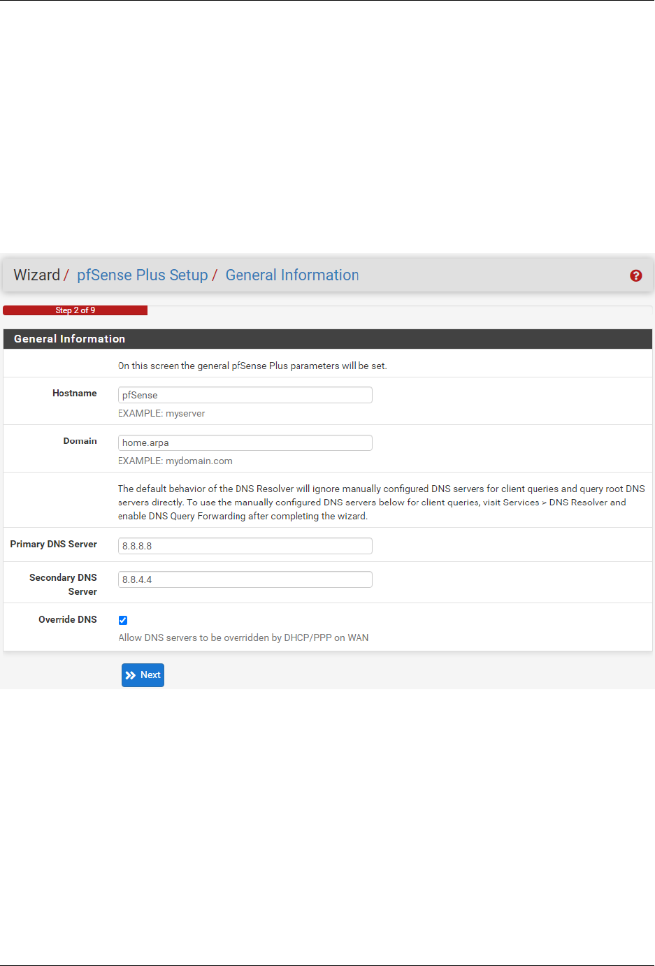
3. Use the following items as a guide to configure the options on the General Information page:
Hostname
Any desired hostname name can be entered to identify the firewall. For the purposes of this guide,
the default hostname pfsense is used.
Domain
The domain name under which the firewall operates. The default home.arpa is used for the
purposes of this tutorial.
DNS Servers
For purposes of this setup guide, use the Google public DNS servers (8.8.8.8 and 8.8.4.4).
Note: The firewall defaults to acting as a resolver and clients will not utilize these forwarding
DNS servers. However, these servers give the firewall itself a way to ensure it has working DNS
if resolving the default way does not work properly.
Type in the DNS Server information and Click Next.
4. Use the following information for the Time Server Information page:
Time Server Hostname
Use the default time server address. The default hostname is suitable for both IPv4 and IPv6 NTP
clients.
Timezone
Select a geographically named time zone for the location of the firewall.
© Copyright 2024 Rubicon Communications LLC 6
Security Gateway Manual SG-1100
Fig. 4: General Information page in the Setup Wizard
© Copyright 2024 Rubicon Communications LLC 7

Security Gateway Manual SG-1100
For this guide, the Timezone will be set to America/Chicago for US Central time.
Fig. 5: Time Server Information page in the Setup Wizard
Change the Timezone and click Next.
5. Use the following information for the Configure WAN Interface page:
The WAN interface is the external (public) IP address the firewall will use to communicate with the Internet.
DHCP is the default and is the most common type of WAN interface for home fiber and cable modems.
Default settings for the other items on this page should be acceptable for normal home users.
Default settings should be acceptable. Click Next.
6. Configuring LAN IP Address & Subnet Mask. The default LAN IP address of 192.168.1.1 and subnet mask
of 24 is usually sufficient.
Tip: If the CPE on WAN (e.g. Fiber or Cable Modem) has a default IP Address of 192.168.1.1, the Ethernet
cable should be disconnected from the WAN port on the Netgate 1100 Security Gateway before starting.
Change the default LAN IP Address of the device during this step in the configuration to avoid having conflicting
subnets on the WAN and LAN.
7. Change the Admin Password. Enter the same new password in both fields.
8. Click Reload to save the configuration.
9. After a few seconds, a message will indicate the Setup Wizard has completed. To proceed to the pfSense
®
Plus
dashboard, click Finish.
Note: This step of the wizard also contains several useful links to Netgate resources and methods of obtaining
assistance with the product. Be sure to read through the items on this page before finishing the wizard.
© Copyright 2024 Rubicon Communications LLC 8

Security Gateway Manual SG-1100
Fig. 6: Configure WAN Interface page in the Setup Wizard
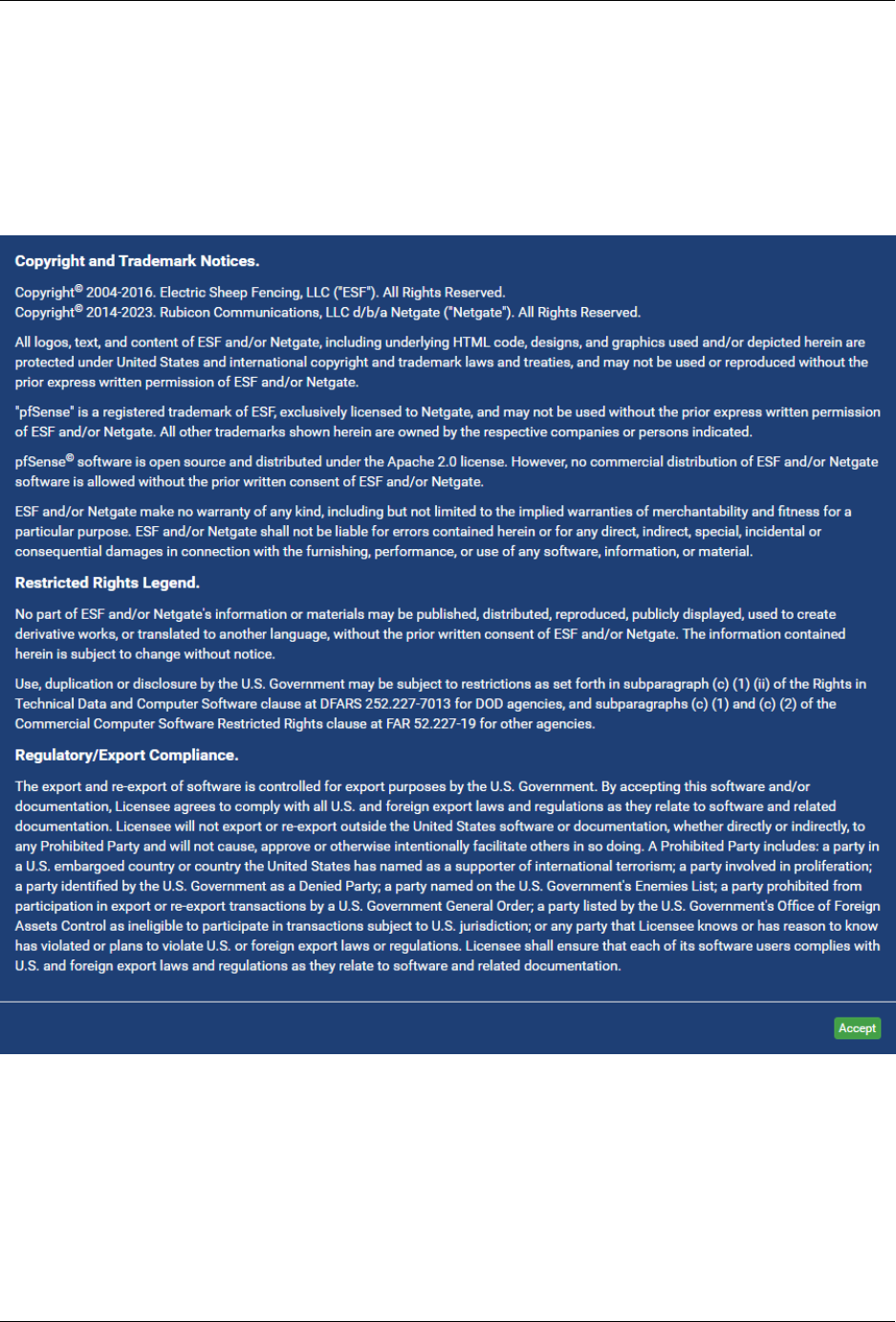
1.2.3 Finishing Up
After completing or exiting the wizard, during the first time loading the Dashboard the firewall will display a notifi-
cation modal dialog with the Copyright and Trademark Notices.
Read and click Accept to continue to the dashboard.
If the Ethernet cable was unplugged at the beginning of this configuration, reconnect it to the WAN port now.
This completes the basic configuration for the Netgate appliance.
© Copyright 2024 Rubicon Communications LLC 9
Security Gateway Manual SG-1100
Fig. 7: Copyright and Trademark Notices
© Copyright 2024 Rubicon Communications LLC 10

Security Gateway Manual SG-1100
1.3 pfSense Plus Software Overview
This page provides an overview of the pfSense
®
Plus dashboard and navigation. It also provides information on how to
perform frequent tasks such as backing up the pfSense
®
Plus software and connecting to the Netgate firewall console.
1.3.1 The Dashboard
pfSense
®
Plus software is highly configurable, all of which can be done through the dashboard. This orientation will
help to navigate and further configure the firewall.
Fig. 8: The pfSense
®
Plus Dashboard
Section 1
Important system information such as the model, Serial Number, and Netgate Device ID for this Netgate firewall.
Section 2
Identifies what version of pfSense
®
Plus software is installed, and if an update is available.
Section 3
Describes Netgate Service and Support.
Section 4
Shows the various menu headings. Each menu heading has drop-down options for a wide range of configuration
choices.
© Copyright 2024 Rubicon Communications LLC 11

Security Gateway Manual SG-1100
1.3.2 Re-running the Setup Wizard
To re-run the Setup Wizard, navigate to System > Setup Wizard.
Fig. 9: Re-run the Setup Wizard
1.3.3 Backup and Restore
It is important to backup the firewall configuration prior to updating or making any configuration changes. From the
menu at the top of the page, browse to Diagnostics > Backup/Restore.
Click Download configuration as XML and save a copy of the firewall configuration to the computer connected to
the Netgate firewall.
This backup (or any backup) can be restored from the same screen by choosing the backed up file under Restore
Configuration.
Note: Auto Config Backup is a built-in service located at Services > Auto Config Backup. This service will save
up to 100 encrypted backup files automatically, any time a change to the configuration has been made. Visit the Auto
Config Backup page for more information.
© Copyright 2024 Rubicon Communications LLC 12

Security Gateway Manual SG-1100
Fig. 10: Backup & Restore
Fig. 11: Click Download configuration as XML
© Copyright 2024 Rubicon Communications LLC 13

Security Gateway Manual SG-1100
1.3.4 Connecting to the Console
There are times when accessing the console is required. Perhaps GUI console access has been locked out, or the
password has been lost or forgotten.
See also:
Connecting to the USB Console Port. Cable is required.
Tip: To learn more about getting the most out of a Netgate appliance, sign up for a pfSense Plus Software Training
course or browse the extensive Resource Library.
1.3.5 Updates
When a new version of pfSense Plus software is available, the device will indicate the availability of the new version
on the System Information dashboard widget. Users can peform a manual check as well by visiting System > Update.
Users can initiate an upgrade from the System > Update page as needed.
For more information, see the Upgrade Guide.
Warning: Depending on the configuration, running services, and installed packages, the Netgate 1100 may not
have sufficient available RAM to run upgrades. Temporarily disabling packages and services which consume large
amounts of RAM can help work around this limitation.
Some older installations of pfSense Plus software on Netgate 1100 devices contain an EFI partition which does
not have sufficient space to accommodate the new EFI loader for version 23.01 and later. This primarily affects
UFS-based systems initially installed with version 21.02-p1 or before.
For details on these issues and more, see Troubleshooting Upgrades on Netgate 1100 and Netgate 2100 Devices.
1.4 Input and Output Ports
1.4.1 Front Side
Fig. 12: Front view of the Netgate 1100 Firewall Appliance
The items in this image are described by entries in Ethernet Ports and Other Front Ports.
© Copyright 2024 Rubicon Communications LLC 14

Security Gateway Manual SG-1100
Ethernet Ports
Interface Name Port Name Port Type Port Speed
WAN mvneta0.4090 RJ-45 1 Gbps
LAN mvneta0.4091 RJ-45 1 Gbps
OPT mvneta0.4092 RJ-45 1 Gbps
The Ethernet ports are switched ports. By default these ports are configured as discrete interfaces on separate VLANs.
Note: For more details on how the switch operates, see Switch Overview.
For instructions on how to configure the switch see Configuring the Switch Ports.
Other Front Ports
• 1x USB 2.0 Port (left side)
• 1x USB 3.0 Ports (right side)
USB Ports
USB ports on the device can be used for a variety of purposes.
The primary use for the USB ports is to install or reinstall the operating system on the device. Beyond that, there
are numerous USB devices which can expand the base functionality of the hardware, including some supported by
add-on packages. For example, UPS/Battery Backups, Cellular modems, GPS units, and storage devices. Though the
operating system also supports wired and wireless network devices, these are not ideal and should be avoided.
1.4.2 Rear Side
Fig. 13: Rear view of the Netgate 1100 Firewall Appliance
From left to right:
1. Power Connector
• 12VDC 2A Center Pin Positive
• Power Consumption 3.48W (Idle)
2. Micro-USB Serial Console
© Copyright 2024 Rubicon Communications LLC 15

Security Gateway Manual SG-1100
3. Recessed Reset Button (performs a hard reset, immediately turning the system off)
Warning: A hard reset of the system could cause data corruption and should be avoided. Halt or reboot the system
through the console menu or the GUI to avoid data corruption.
1.4.3 Top Side
LED Patterns
Table 1: Indicators
Status LED State Description
Black Diamond Blink Fast pfSense
®
Plus boot in progress
Solid pfSense
®
Plus boot complete
Blink Slow pfSense
®
Plus software upgrade is available
Blue Square Active mPCIe Expansion Slot Activity (not supported)
Green Circle Solid Power
Note: Though the system board has a Mini-PCI Express (mPCIe) expansion slot, it is not currently supported.
1.5 Safety and Legal
1.5.1 Safety Notices
1. Read, follow, and keep these instructions.
2. Heed all warnings.
3. Only use attachments/accessories specified by the manufacturer.
Warning: Do not use this product in location that can be submerged by water.
Warning: Do not use this product during an electrical storm to avoid electrical shock.
© Copyright 2024 Rubicon Communications LLC 16

Security Gateway Manual SG-1100
1.5.2 Electrical Safety Information
1. Compliance is required with respect to voltage, frequency, and current requirements indicated on the manu-
facturer’s label. Connection to a different power source than those specified may result in improper operation,
damage to the equipment or pose a fire hazard if the limitations are not followed.
2. There are no operator serviceable parts inside this equipment. Service should be provided only by a qualified
service technician.
3. This equipment is provided with a detachable power cord which has an integral safety ground wire intended for
connection to a grounded safety outlet.
a) Do not substitute the power cord with one that is not the provided approved type. If a 3 prong plug is
provided, never use an adapter plug to connect to a 2-wire outlet as this will defeat the continuity of the
grounding wire.
b) The equipment requires the use of the ground wire as a part of the safety certification, modification or
misuse can provide a shock hazard that can result in serious injury or death.
c) Contact a qualified electrician or the manufacturer if there are questions about the installation prior to
connecting the equipment.
d) Protective grounding/earthing is provided by Listed AC adapter. Building installation shall provide appro-
priate short-circuit backup protection.
e) Protective bonding must be installed in accordance with local national wiring rules and regulations.
1.5.3 FCC Compliance
Changes or modifications not expressly approved by the party responsible for compliance could void the user’s authority
to operate the equipment. This device complies with Part 15 of the FCC Rules. Operation is subject to the following
two conditions:
1. This device may not cause harmful interference, and
2. This device must accept any interference received, including interference that may cause undesired operation.
Note: This equipment has been tested and found to comply with the limits for a Class B digital device, pursuant to part
15 of the FCC Rules. These limits are designed to provide reasonable protection against harmful interference when the
equipment is operated in a residential environment.
1.5.4 Industry Canada
This Class B digital apparatus complies with Canadian ICES-3(B). Cet appareil numérique de la classe B est conforme
à la norme NMB-3(B) Canada.
© Copyright 2024 Rubicon Communications LLC 17

Security Gateway Manual SG-1100
1.5.5 CE Marking
CE marking on this product represents the product is in compliance with all directives that are applicable to it.
1.5.6 RoHS/WEEE Compliance Statement
English
European Directive 2002/96/EC requires that the equipment bearing this symbol on the product and/or its packaging
must not be disposed of with unsorted municipal waste. The symbol indicates that this product should be disposed
of separately from regular household waste streams. It is your responsibility to dispose of this and other electric and
electronic equipment via designated collection facilities appointed by the government or local authorities. Correct
disposal and recycling will help prevent potential negative consequences to the environment and human health. For
more detailed information about the disposal of your old equipment, please contact your local authorities, waste disposal
service, or the shop where you purchased the product.
Deutsch
Die Europäische Richtlinie 2002/96/EC verlangt, dass technische Ausrüstung, die direkt am Gerät und/oder an der
Verpackung mit diesem Symbol versehen ist, nicht zusammen mit unsortiertem Gemeindeabfall entsorgt werden darf.
Das Symbol weist darauf hin, dass das Produkt von regulärem Haushaltmüll getrennt entsorgt werden sollte. Es liegt in
Ihrer Verantwortung, dieses Gerät und andere elektrische und elektronische Geräte über die dafür zuständigen und von
der Regierung oder örtlichen Behörden dazu bestimmten Sammelstellen zu entsorgen. Ordnungsgemäßes Entsorgen
und Recyceln trägt dazu bei, potentielle negative Folgen für Umwelt und die menschliche Gesundheit zu vermeiden.
Wenn Sie weitere Informationen zur Entsorgung Ihrer Altgeräte benötigen, wenden Sie sich bitte an die örtlichen
Behörden oder städtischen Entsorgungsdienste oder an den Händler, bei dem Sie das Produkt erworben haben.
Español
La Directiva 2002/96/CE de la UE exige que los equipos que lleven este símbolo en el propio aparato y/o en su embalaje
no deben eliminarse junto con otros residuos urbanos no seleccionados. El símbolo indica que el producto en cuestión
debe separarse de los residuos domésticos convencionales con vistas a su eliminación. Es responsabilidad suya desechar
este y cualesquiera otros aparatos eléctricos y electrónicos a través de los puntos de recogida que ponen a su disposición
el gobierno y las autoridades locales. Al desechar y reciclar correctamente estos aparatos estará contribuyendo a evitar
posibles consecuencias negativas para el medio ambiente y la salud de las personas. Si desea obtener información más
detallada sobre la eliminación segura de su aparato usado, consulte a las autoridades locales, al servicio de recogida y
eliminación de residuos de su zona o pregunte en la tienda donde adquirió el producto.
Français
La directive européenne 2002/96/CE exige que l’équipement sur lequel est apposé ce symbole sur le produit et/ou son
emballage ne soit pas jeté avec les autres ordures ménagères. Ce symbole indique que le produit doit être éliminé dans
un circuit distinct de celui pour les déchets des ménages. Il est de votre responsabilité de jeter ce matériel ainsi que
tout autre matériel électrique ou électronique par les moyens de collecte indiqués par le gouvernement et les pouvoirs
publics des collectivités territoriales. L’élimination et le recyclage en bonne et due forme ont pour but de lutter contre
l’impact néfaste potentiel de ce type de produits sur l’environnement et la santé publique. Pour plus d’informations sur
le mode d’élimination de votre ancien équipement, veuillez prendre contact avec les pouvoirs publics locaux, le service
de traitement des déchets, ou l’endroit où vous avez acheté le produit.
© Copyright 2024 Rubicon Communications LLC 18

Security Gateway Manual SG-1100
Italiano
La direttiva europea 2002/96/EC richiede che le apparecchiature contrassegnate con questo simbolo sul prodotto e/o
sull’imballaggio non siano smaltite insieme ai rifiuti urbani non differenziati. Il simbolo indica che questo prodotto non
deve essere smaltito insieme ai normali rifiuti domestici. È responsabilità del proprietario smaltire sia questi prodotti
sia le altre apparecchiature elettriche ed elettroniche mediante le specifiche strutture di raccolta indicate dal governo o
dagli enti pubblici locali. Il corretto smaltimento ed il riciclaggio aiuteranno a prevenire conseguenze potenzialmente
negative per l’ambiente e per la salute dell’essere umano. Per ricevere informazioni più dettagliate circa lo smaltimento
delle vecchie apparecchiature in Vostro possesso, Vi invitiamo a contattare gli enti pubblici di competenza, il servizio
di smaltimento rifiuti o il negozio nel quale avete acquistato il prodotto.
1.5.7 Declaration of Conformity
Česky[Czech]
NETGATE tímto prohla uje, e tento NETGATE device, je ve shod se základními po adavky a dal ími p íslu n mi
ustanoveními sm rnice 1999/5/ES.
Dansk [Danish]
Undertegnede NETGATE erklærer herved, at følgende udstyr NETGATE device, overholder de væsentlige krav og
øvrige relevante krav i direktiv 1999/5/EF.
Nederlands [Dutch]
Hierbij verklaart NETGATE dat het toestel NETGATE device, in overeenstemming is met de essentiële eisen en de
andere relevante bepalingen van richtlijn 1999/5/EG. Bij deze verklaart NETGATE dat deze NETGATE device, voldoet
aan de essentiële eisen en aan de overige relevante bepalingen van Richtlijn 1999/5/EC.
English
Hereby, NETGATE , declares that this NETGATE device, is in compliance with the essential requirements and other
relevant provisions of Directive 1999/5/EC.
Eesti [Estonian]
Käesolevaga kinnitab NETGATE seadme NETGATE device, vastavust direktiivi 1999/5/EÜ põhinõuetele ja nimetatud
direktiivist tulenevatele teistele asjakohastele sätetele.
Suomi [Finnish]
NETGATE vakuuttaa täten että NETGATE device, tyyppinen laite on direktiivin 1999/5/EY oleellisten vaatimusten
ja sitä koskevien direktiivin muiden ehtojen mukainen. Français [French] Par la présente NETGATE déclare que
l’appareil Netgate, device est conforme aux exigences essentielles et aux autres dispositions pertinentes de la directive
1999/5/CE.
© Copyright 2024 Rubicon Communications LLC 19

Security Gateway Manual SG-1100
Deutsch [German]
Hiermit erklärt Netgate, dass sich diese NETGATE device, in Übereinstimmung mit den grundlegenden Anforderungen
und den anderen relevanten Vorschriften der Richtlinie 1999/5/EG befindet”. (BMWi)
ΕλληνικH [Greek]
ΜΕ ΤΗΝ ΠΑΡΟΥΣΑ NETGATE ΔΗΛΩΝΕΙ ΟΤΙ NETGATE device, ΣΥΜΜΟΡΦΩΝΕΤΑΙ ΠΡΟΣ ΤΙΣ ΟΥΣΙ-
ΩΔΕΙΣ ΑΠΑΙΤΗΣΕΙΣ ΚΑΙ ΤΙΣ ΛΟΙΠΕΣ ΣΧΕΤΙΚΕΣ ΔΙΑΤΑΞΕΙΣ ΤΗΣ ΟΔΗΓΙΑΣ 1995/5/ΕΚ.
Magyar [Hungarian]
Alulírott, NETGATE nyilatkozom, hogy a NETGATE device, megfelel a vonatkozó alapvetõ követelményeknek és az
1999/5/EC irányelv egyéb elõírásainak.
Íslenska [Icelandic]
Hér me l sir NETGATE yfir ví a NETGATE device, er í samræmi vi grunnkröfur og a rar kröfur, sem ger ar eru í
tilskipun 1999/5/EC.
Italiano [Italian]
Con la presente NETGATE dichiara che questo NETGATE device, è conforme ai requisiti essenziali ed alle altre
disposizioni pertinenti stabilite dalla direttiva 1999/5/CE.
Latviski [Latvian]
Ar o NETGATE deklar , ka NETGATE device, atbilst Direkt vas 1999/5/EK b tiskaj m pras b m un citiem ar to saist
tajiem noteikumiem.
Lietuviškai [Lithuanian]
NETGATE deklaruoja, kad šis NETGATE i˛renginys atitinka esminius reikalavimus ir kitas 1999/5/EB Direktyvos
nuostatas.
Malti [Maltese]
Hawnhekk, Netgate, jiddikjara li dan NETGATE device, jikkonforma mal- ti ijiet essenzjali u ma provvedimenti o rajn
relevanti li hemm fid-Dirrettiva 1999/5/EC.
© Copyright 2024 Rubicon Communications LLC 20

Security Gateway Manual SG-1100
Norsk [Norwegian]
NETGATE erklærer herved at utstyret NETGATE device, er i samsvar med de grunnleggende krav og øvrige relevante
krav i direktiv 1999/5/EF.
Slovensky [Slovak]
NETGATE t mto vyhlasuje, e NETGATE device, sp a základné po iadavky a v etky príslu né ustanovenia Smernice
1999/5/ES.
Svenska [Swedish]
Härmed intygar NETGATE att denna NETGATE device, står I överensstämmelse med de väsentliga egenskapskrav
och övriga relevanta bestämmelser som framgår av direktiv 1999/5/EG.
Español [Spanish]
Por medio de la presente NETGATE declara que el NETGATE device, cumple con los requisitos esenciales y cua-
lesquiera otras disposiciones aplicables o exigibles de la Directiva 1999/5/CE.
Polski [Polish]
Niniejszym, firma NETGATE o wiadcza, e produkt serii NETGATE device, spełnia zasadnicze wymagania i inne
istotne postanowienia Dyrektywy 1999/5/EC.
Português [Portuguese]
NETGATE declara que este NETGATE device, está conforme com os requisitos essenciais e outras disposições da
Directiva 1999/5/CE.
Română [Romanian]
Prin prezenta, NETGATE declară că acest dispozitiv NETGATE este în conformitate cu cerint
,
ele esent
,
iale s
,
i alte
prevederi relevante ale Directivei 1999/5/CE.
1.5.8 Disputes
ANY DISPUTE OR CLAIM RELATING IN ANY WAY TO YOUR USE OF ANY PRODUCTS/SERVICES, OR
TO ANY PRODUCTS OR SERVICES SOLD OR DISTRIBUTED BY RCL OR ESF WILL BE RESOLVED BY
BINDING ARBITRATION IN AUSTIN, TEXAS, RATHER THAN IN COURT. The Federal Arbitration Act and
federal arbitration law apply to this agreement.
THERE IS NO JUDGE OR JURY IN ARBITRATION, AND COURT REVIEW OF AN ARBITRATION AWARD
IS LIMITED. HOWEVER, AN ARBITRATOR CAN AWARD ON AN INDIVIDUAL BASIS THE SAME DAM-
AGES AND RELIEF AS A COURT (INCLUDING INJUNCTIVE AND DECLARATORY RELIEF OR STATU-
TORY DAMAGES), AND MUST FOLLOW THE TERMS OF THESE TERMS AND CONDITIONS OF USE AS A
COURT WOULD.
To begin an arbitration proceeding, you must send a letter requesting arbitration and describing your claim to the
following:
© Copyright 2024 Rubicon Communications LLC 21

Security Gateway Manual SG-1100
Rubicon Communications LLC
Attn.: Legal Dept.
4616 West Howard Lane, Suite 900
Austin, Texas 78728
legal@netgate.com
The arbitration will be conducted by the American Arbitration Association (AAA) under its rules. The AAA’s rules
are available at www.adr.org. Payment of all filing, administration and arbitrator fees will be governed by the AAA’s
rules.
We each agree that any dispute resolution proceedings will be conducted only on an individual basis and not in a class,
consolidated or representative action. We also both agree that you or we may bring suit in court to enjoin infringement
or other misuse of intellectual property rights.
1.5.9 Applicable Law
By using any Products/Services, you agree that the Federal Arbitration Act, applicable federal law, and the laws of
the state of Texas, without regard to principles of conflict of laws, will govern these terms and conditions of use and
any dispute of any sort that might arise between you and RCL and/or ESF. Any claim or cause of action concerning
these terms and conditions or use of the RCL and/or ESF website must be brought within one (1) year after the claim
or cause of action arises. Exclusive jurisdiction and venue for any dispute or claim arising out of or relating to the
parties’ relationship, these terms and conditions, or the RCL and/or ESF website, shall be with the arbitrator and/or
courts located in Austin, Texas. The judgment of the arbitrator may be enforced by the courts located in Austin, Texas,
or any other court having jurisdiction over you.
1.5.10 Site Policies, Modification, and Severability
Please review our other policies, such as our pricing policy, posted on our websites. These policies also govern your
use of Products/Services. We reserve the right to make changes to our site, policies, service terms, and these terms and
conditions of use at any time.
1.5.11 Miscellaneous
If any provision of these terms and conditions of use, or our terms and conditions of sale, are held to be invalid, void
or unenforceable, the invalid, void or unenforceable provision shall be modified to the minimum extent necessary in
order to render it valid or enforceable and in keeping with the intent of these terms and conditions. If such modification
is not possible, the invalid or unenforceable provision shall be severed, and the remaining terms and conditions shall
be enforced as written. Headings are for reference purposes only and in no way define, limit, construe or describe the
scope or extent of such section. Our failure to act with respect to a breach by you or others does not waive our right
to act with respect to subsequent or similar breaches. These terms and conditions set forth the entire understanding
and agreement between us with respect to the subject matter hereof, and supersede any prior oral or written agreement
pertaining thereto, except as noted above with respect to any conflict between these terms and conditions and our reseller
agreement, if the latter is applicable to you.
© Copyright 2024 Rubicon Communications LLC 22

Security Gateway Manual SG-1100
1.5.12 Limited Warranty
DISCLAIMER OF WARRANTIES AND LIMITATION OF LIABILITY
THE PRODUCTS/SERVICES AND ALL INFORMATION, CONTENT, MATERIALS, PRODUCTS (INCLUD-
ING SOFTWARE) AND OTHER SERVICES INCLUDED ON OR OTHERWISE MADE AVAILABLE TO YOU
THROUGH THE PRODUCTS/SERVICES ARE PROVIDED BY US ON AN “AS IS” AND “AS AVAILABLE” BA-
SIS, UNLESS OTHERWISE SPECIFIED IN WRITING. WE MAKE NO REPRESENTATIONS OR WARRANTIES
OF ANY KIND, EXPRESS OR IMPLIED, AS TO THE OPERATION OF THE PRODUCTS/SERVICES, OR THE
INFORMATION, CONTENT, MATERIALS, PRODUCTS (INCLUDING SOFTWARE) OR OTHER SERVICES IN-
CLUDED ON OR OTHERWISE MADE AVAILABLE TO YOU THROUGH THE PRODUCTS/SERVICES, UN-
LESS OTHERWISE SPECIFIED IN WRITING. YOU EXPRESSLY AGREE THAT YOUR USE OF THE PROD-
UCTS/SERVICES IS AT YOUR SOLE RISK.
TO THE FULL EXTENT PERMISSIBLE BY APPLICABLE LAW, RUBICON COMMUNICATIONS, LLC (RCL)
AND ELECTRIC SHEEP FENCING (ESF) DISCLAIM ALL WARRANTIES, EXPRESS OR IMPLIED, INCLUD-
ING, BUT NOT LIMITED TO, IMPLIED WARRANTIES OF MERCHANTABILITY AND FITNESS FOR A PAR-
TICULAR PURPOSE. RCL AND ESF DO NOT WARRANT THAT THE PRODUCTS/SERVICES, INFORMA-
TION, CONTENT, MATERIALS, PRODUCTS (INCLUDING SOFTWARE) OR OTHER SERVICES INCLUDED
ON OR OTHERWISE MADE AVAILABLE TO YOU THROUGH THE PRODUCTS/SERVICES, RCL’S OR ESF’S
SERVERS OR ELECTRONIC COMMUNICATIONS SENT FROM RCL OR ESF ARE FREE OF VIRUSES OR
OTHER HARMFUL COMPONENTS. RCL AND ESF WILL NOT BE LIABLE FOR ANY DAMAGES OF ANY
KIND ARISING FROM THE USE OF ANY PRODUCTS/SERVICES, OR FROM ANY INFORMATION, CON-
TENT, MATERIALS, PRODUCTS (INCLUDING SOFTWARE) OR OTHER SERVICES INCLUDED ON OR OTH-
ERWISE MADE AVAILABLE TO YOU THROUGH ANY PRODUCTS/SERVICES, INCLUDING, BUT NOT LIM-
ITED TO DIRECT, INDIRECT, INCIDENTAL, PUNITIVE, AND CONSEQUENTIAL DAMAGES, UNLESS OTH-
ERWISE SPECIFIED IN WRITING.
IN NO EVENT WILL RCL’S OR ESF’S LIABILITY TO YOU EXCEED THE PURCHASE PRICE PAID FOR
THE PRODUCT OR SERVICE THAT IS THE BASIS OF THE CLAIM.
CERTAIN STATE LAWS DO NOT ALLOW LIMITATIONS ON IMPLIED WARRANTIES OR THE EXCLUSION
OR LIMITATION OF CERTAIN DAMAGES. IF THESE LAWS APPLY TO YOU, SOME OR ALL OF THE ABOVE
DISCLAIMERS, EXCLUSIONS, OR LIMITATIONS MAY NOT APPLY TO YOU, AND YOU MIGHT HAVE AD-
DITIONAL RIGHTS.
© Copyright 2024 Rubicon Communications LLC 23

CHAPTER
TWO
HOW-TO GUIDES
2.1 Installing the Wall Mount Kit
This page shows how to install the optional Netgate 1100 Wall Mount Kit.
Tip: Save the Netgate 1100 MAC Address, Serial Number, and NDI, located on the bottom of the system, before
attaching the Netgate 1100 to the wall.
Fig. 1: Loop one side of the Silcone Band under the wall mount of the Netgate 1100
24

Security Gateway Manual SG-1100
Fig. 2: Stretch the Silicone Band to the opposite side of the wall mount
© Copyright 2024 Rubicon Communications LLC 25

Security Gateway Manual SG-1100
© Copyright 2024 Rubicon Communications LLC 26

Security Gateway Manual SG-1100
Fig. 3: Loop the silicone band under the opposite side of the wall mount
© Copyright 2024 Rubicon Communications LLC 27

Security Gateway Manual SG-1100
Fig. 4: The silicone band should look like this
© Copyright 2024 Rubicon Communications LLC 28

Security Gateway Manual SG-1100
Fig. 5: Tuck both sides of the silicone band under the wall mount
© Copyright 2024 Rubicon Communications LLC 29

Security Gateway Manual SG-1100
Note: Remove the rubber standoff feet from the Netgate 1100 prior to attaching to the wall mount. Do not remove
the screws that are under the rubber standoff feet.
Fig. 6: Place the Netgate 1100 over the silver aluminum standoffs on the wall mount and pull one side of the silicone
band over the Netgate 1100, then the other
Tip: Remember to save the Netgate 1100 MAC Address, Serial Number, and NDI, located on the bottom of the system,
before attaching the Netgate 1100 to the wall.
Hang the wall mount with the cables hanging down. Secure the cables to the holes on the wall mount with cable ties
to relieve the weight from the ports.
© Copyright 2024 Rubicon Communications LLC 30

Security Gateway Manual SG-1100
Fig. 7: When mounted properly, the Netgate 1100 should look like this
© Copyright 2024 Rubicon Communications LLC 31

Security Gateway Manual SG-1100
Fig. 8: Note the silicone band under the Netgate 1100 when installed correctly
© Copyright 2024 Rubicon Communications LLC 32

Security Gateway Manual SG-1100
Fig. 9: An Netgate 1100 wall mount kit correctly installed
© Copyright 2024 Rubicon Communications LLC 33

Security Gateway Manual SG-1100
2.2 Connecting to the USB Console Port
This guide shows how to access the serial console which can be used for troubleshooting and diagnostics tasks as well
as some basic configuration.
There are times when directly accessing the console is required. Perhaps GUI or SSH access has been locked out, or
the password has been lost or forgotten.
2.2.1 Install the Driver
A Prolific PL2303 USB-to-UART Bridge driver is used to provide access to the console, which is exposed via the
USB Micro-B (5-pin) port on the appliance.
If needed, install an appropriate Prolific PL2303 USB to UART Bridge driver on the workstation used to connect with
the device.
Windows
There are drivers available for Windows available for download.
macOS
There are drivers available for macOS available for download.
Linux
There are drivers available for Linux available for download.
Recent versions of many Linux distributions include this driver and will not require manual installation.
FreeBSD
Recent versions of FreeBSD include this driver and will not require manual installation.
2.2.2 Connect a USB Cable
Next, locate an appropriate USB cable that has a USB Micro-B (5-pin) connector on one end and a regular USB Type
A plug on the other end. These cables are commonly used with smaller USB peripherals such as GPS units, cameras,
and so on.
Gently push the USB Micro-B (5-pin) plug end into the console port on the appliance and connect the USB Type A
plug into an available USB port on the workstation.
Tip: Be certain to gently push in the USB Micro-B (5-pin) connector on the device side completely. With most cables
there will be a tangible “click”, “snap”, or similar indication when the cable is fully engaged.
© Copyright 2024 Rubicon Communications LLC 34

Security Gateway Manual SG-1100
2.2.3 Apply Power to the Device
On some devices when using a USB serial console port the serial port will not appear on the client operating system
until the device is plugged into a power source.
If the client OS does not see the serial device, connect the power cord to the device to allow it to start booting.
If the device appears without power, then better to wait until the terminal is open before connecting power so the client
can view the entire boot output.
2.2.4 Locate the Console Port Device
The appropriate console port device that the workstation assigned as the serial port must be located before attempting
to connect to the console.
Note: Even if the serial port was assigned in the BIOS, the workstation OS may remap it to a different COM Port.
Windows
To locate the device name on Windows, open Device Manager and expand the section for Ports (COM & LPT).
Look for an entry with a title such as Prolific USB-to-Serial Comm Port. If there is a label in the name that contains
“COMX” where X is a decimal digit (e.g. COM3), that value is what would be used as the port in the terminal program.
macOS
The device associated with the system console is likely to show up as, or start with, /dev/cu.usbserial-<id>.
Run ls -l /dev/cu.* from a Terminal prompt to see a list of available USB serial devices and locate the appropriate
one for the hardware. If there are multiple devices, the correct device is likely the one with the most recent timestamp
or highest ID.
Linux
The device associated with the system console is likely to show up as /dev/ttyUSB0. Look for messages about the
device attaching in the system log files or by running dmesg.
Note: If the device does not appear in /dev/, see the note above in the driver section about manually loading the
Linux driver and then try again.
FreeBSD
© Copyright 2024 Rubicon Communications LLC 35

Security Gateway Manual SG-1100
The device associated with the system console is likely to show up as /dev/cuaU0. Look for messages about the device
attaching in the system log files or by running dmesg.
Note: If the serial device is not present, ensure the device has power and then check again.
2.2.5 Launch a Terminal Program
Use a terminal program to connect to the system console port. Some choices of terminal programs:
Windows
For Windows the best practice is to run PuTTY in Windows or SecureCRT. An example of how to configure PuTTY is
below.
Warning: Do not use Hyperterminal.
macOS
For macOS the best practice is to run GNU screen, or cu. An example of how to configure GNU screen is below.
Linux
For Linux the best practices are to run GNU screen, PuTTY in Linux, minicom, or dterm. Examples of how to
configure PuTTY and GNU screen are below.
FreeBSD
For FreeBSD the best practice is to run GNU screen or cu. An example of how to configure GNU screen is below.
Client-Specific Examples
PuTTY in Windows
• Open PuTTY and select Session under Category on the left hand side.
• Set the Connection type to Serial
• Set Serial line to the console port determined previously
• Set the Speed to 115200 bits per second.
• Click the Open button
PuTTY will then display the console.
© Copyright 2024 Rubicon Communications LLC 36

Security Gateway Manual SG-1100
Fig. 10: An example of using PuTTY in Windows
© Copyright 2024 Rubicon Communications LLC 37
Security Gateway Manual SG-1100
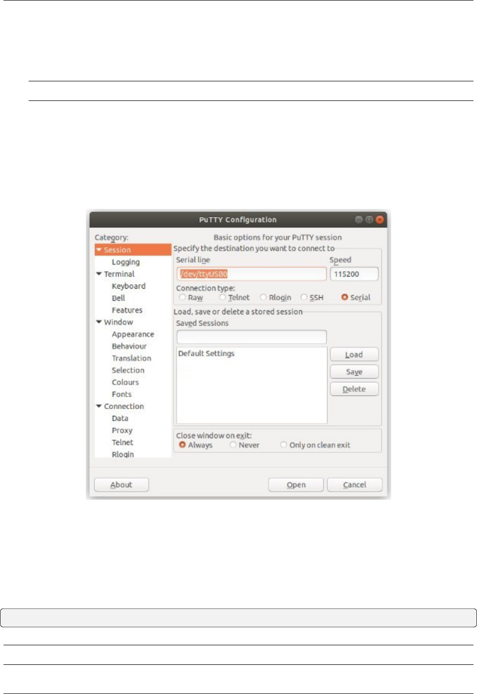
PuTTY in Linux
• Open PuTTY from a terminal by typing sudo putty
Note: The sudo command will prompt for the local workstation password of the current account.
• Set the Connection type to Serial
• Set Serial line to /dev/ttyUSB0
• Set the Speed to 115200 bits per second
• Click the Open button
PuTTY will then display the console.
Fig. 11: An example of using PuTTY in Linux
GNU screen
In many cases screen may be invoked simply by using the proper command line, where <console-port> is the
console port that was located above.
$ sudo screen <console-port> 115200
Note: The sudo command will prompt for the local workstation password of the current account.
© Copyright 2024 Rubicon Communications LLC 38

Security Gateway Manual SG-1100
If portions of the text are unreadable but appear to be properly formatted, the most likely culprit is a character encoding
mismatch in the terminal. Adding the -U parameter to the screen command line arguments forces it to use UTF-8 for
character encoding:
$ sudo screen -U <console-port> 115200
Terminal Settings
The settings to use within the terminal program are:
Speed
115200 baud, the speed of the BIOS
Data bits
8
Parity
None
Stop bits
1
Flow Control
Off or XON/OFF.
Warning: Hardware flow control (RTS/CTS) must be disabled.
Terminal Optimization
Beyond the required settings there are additional options in terminal programs which will help input behavior and
output rendering to ensure the best experience. These settings vary location and support by client, and may not be
available in all clients or terminals.
These are:
Terminal Type
xterm
This setting may be under Terminal, Terminal Emulation, or similar areas.
Color Support
ANSI colors / 256 Color / ANSI with 256 Colors
This setting may be under Terminal Emulation, Window Colors, Text, Advanced Terminfo, or similar
areas.
Character Set / Character Encoding
UTF-8
This setting may be under Terminal Appearance, Window Translation, Advanced International, or
similar areas. In GNU screen this is activated by passing the -U parameter.
Line Drawing
Look for and enable setting such as “Draw lines graphically”, “Use unicode graphics characters”,
and/or “Use Unicode line drawing code points”.
These settings may be under Terminal Appearance, Window Translation, or similar areas.
© Copyright 2024 Rubicon Communications LLC 39

Security Gateway Manual SG-1100
Function Keys / Keypad
Xterm R6
In Putty this is under Terminal > Keyboard and is labeled The Function Keys and Keypad.
Font
For the best experience, use a modern monospace unicode font such as Deja Vu Sans Mono, Liber-
ation Mono, Monaco, Consolas, Fira Code, or similar.
This setting may be under Terminal Appearance, Window Appearance, Text, or similar areas.
2.2.6 What’s Next?
After connecting a terminal client, it may not immediately see any output. This could be because the device has already
finished booting or it may be that the device is waiting for some other input.
If the device does not yet have power applied, plug it in and monitor the terminal output.
If the device is already powered on, try pressing Space. If there is still no output, press Enter. If the device was
booted, it may redisplay the console menu or login prompt, or produce other output indicating its status.
From the console, a variety of things are possible, such as changing interface addresses. There is a full explanation of
every console menu option in the pfSense software documentation.
2.2.7 Troubleshooting
Serial Device Missing
With a USB serial console there are a few reasons why the serial port may not be present in the client operating system,
including:
No Power
Some models require power before the client can connect to the USB serial console.
USB Cable Not Plugged In
For USB consoles, the USB cable may not be fully engaged on both ends. Gently, but firmly, ensure the cable
has a good connection on both sides.
Bad USB Cable
Some USB cables are not suitable for use as data cables. For example, some cables are only capable of delivering
power for charging devices and not acting as data cables. Others may be of low quality or have poor or worn
connectors.
The ideal cable to use is the one that came with the device. Failing that, ensure the cable is of the correct type
and specifications, and try multiple cables.
Wrong Device
In some cases there may be multiple serial devices available. Ensure the one used by the serial client is the correct
one. Some devices expose multiple ports, so using the incorrect port may lead to no output or unexpected output.
Hardware Failure
There could be a hardware failure preventing the serial console from working. Contact Netgate TAC for assis-
tance.
© Copyright 2024 Rubicon Communications LLC 40

Security Gateway Manual SG-1100
No Serial Output
If there is no output at all, check the following items:
USB Cable Not Plugged In
For USB consoles, the USB cable may not be fully engaged on both ends. Gently, but firmly, ensure the cable
has a good connection on both sides.
Wrong Device
In some cases there may be multiple serial devices available. Ensure the one used by the serial client is the correct
one. Some devices expose multiple ports, so using the incorrect port may lead to no output or unexpected output.
Wrong Terminal Settings
Ensure the terminal program is configured for the correct speed. The default BIOS speed is 115200, and many
other modern operating systems use that speed as well.
Some older operating systems or custom configurations may use slower speeds such as 9600 or 38400.
Device OS Serial Console Settings
Ensure the operating system is configured for the proper console (e.g. ttyS1 in Linux). Consult the various
operating install guides on this site for further information.
PuTTY has issues with line drawing
PuTTY generally handles most cases OK but can have issues with line drawing characters on certain platforms.
These settings seem to work best (tested on Windows):
Window
Columns x Rows
80x24
Window > Appearance
Font
Courier New 10pt or Consolas 10pt
Window > Translation
Remote Character Set
Use font encoding or UTF-8
Handling of line drawing characters
Use font in both ANSI and OEM modes or Use Unicode line drawing code points
Window > Colours
Indicate bolded text by changing
The colour
© Copyright 2024 Rubicon Communications LLC 41

Security Gateway Manual SG-1100
Garbled Serial Output
If the serial output appears to be garbled, missing characters, binary, or random characters check the following items:
Flow Control
In some cases flow control can interfere with serial communication, causing dropped characters or other issues.
Disabling flow control in the client can potentially correct this problem.
On PuTTY and other GUI clients there is typically a per-session option to disable flow control. In PuTTY, the
Flow Control option is in the settings tree under Connection, then Serial.
To disable flow control in GNU Screen, add the -ixon and/or -ixoff parameters after the serial speed as in the
following example:
$ sudo screen <console port> 115200,-ixon
Terminal Speed
Ensure the terminal program is configured for the correct speed. (See No Serial Output)
Character Encoding
Ensure the terminal program is configured for the proper character encoding, such as UTF-8 or Latin-1, depend-
ing on the operating system. (See GNU Screen)
Serial Output Stops After the BIOS
If serial output is shown for the BIOS but stops afterward, check the following items:
Terminal Speed
Ensure the terminal program is configured for the correct speed for the installed operating system. (See No Serial
Output)
Device OS Serial Console Settings
Ensure the installed operating system is configured to activate the serial console and that it is configured for
the proper console (e.g. ttyS1 in Linux). Consult the various operating install guides on this site for further
information.
Bootable Media
If booting from a USB flash drive, ensure that the drive was written correctly and contains a bootable operating
system image.
2.3 Reinstalling pfSense Plus Software
This guide uses the Netgate Installer to install pfSense® Plus software on a Netgate-1100 device.
Note: pfSense
®
Plus is preinstalled on Netgate appliances. It is optimally tuned for Netgate hardware and contains
features that cannot be found elsewhere, such as ZFS Boot Environments, OpenVPN DCO, Built-in IPFIX Export, and
the AWS VPC Wizard.
© Copyright 2024 Rubicon Communications LLC 42

Security Gateway Manual SG-1100
2.3.1 Download Installation Media
The Netgate Installer can be downloaded from the Netgate Store using a Netgate Store Account.
See also:
For a more detailed walkthrough of the download process, see Download Installation Media in the pfSense Software
Documentation.
The image to download for this device is:
netgate-installer-aarch64.img.gz
2.3.2 Prepare Installation Media
Next, write the installation image to a USB memstick.
See also:
Locating the image and writing it to a USB memstick is covered in detail under Writing Flash Drives.
2.3.3 Connect to the Console
The installation process is interactive and utilizes the console. Follow the directions under Connect to the console to
configure and use the console.
2.3.4 Boot the Installation Media
1. Insert the memstick into the USB port and boot the system.
Tip: The best practice is to connect to the console, turn off the device gracefully by using the Halt system
option from the console and removing power once the shutdown procedure completes, then insert the USB
memstick and boot the device.
Starting the recovery process requires interrupting the boot process very soon after the boot process begins, so
having an active console connection before booting is important.
2. When prompted, press any key to stop the autoboot process.
3. Type run usbrecovery at the Marvell>> prompt and press Enter.
Note: If the device does not boot after issuing this command, enter usb reset and then try run usbrecovery
again. Some USB drives require an extra reset to fully initialize.
© Copyright 2024 Rubicon Communications LLC 43

Security Gateway Manual SG-1100
© Copyright 2024 Rubicon Communications LLC 44

Security Gateway Manual SG-1100
© Copyright 2024 Rubicon Communications LLC 45

Security Gateway Manual SG-1100
2.3.5 Determine Target Drive
During the installation process the installer will prompt to select a target drive. The installer will then write pfSense
®
Plus to the chosen drive. The Netgate-1100 device only supports its internal storage for this purpose, which is mmcsd0.
2.3.6 Install pfSense Plus Software
The installer will automatically launch and present several options. On Netgate appliances, choosing Enter for the
default options will complete the installation process in most cases.
Tip: There are options on the Welcome screen of the installer which can recover configuration data from a previous
installation or from a USB drive.
See also:
For a complete walkthrough of the installation process, see Installation Walkthrough.
When the installation is complete, remove the USB drive from the USB port.
Important: If the USB drive remains attached, the device may boot into the installer again.
See also:
For information on restoring from a previously saved configuration, go to Backup and Restore.
2.4 Configuring the Switch Ports
The default configuration of the Netgate 1100 has each port configured as a discrete interface (WAN, LAN, OPT), but
under the hood the interfaces operate as a switch and the default configuration isolates them by using a separate VLAN
for each port.
This optional guide changes the configuration such that the LAN and OPT Ethernet ports are on the same VLAN,
effectively creating a small two-port LAN switch.
Note: When connecting to the GUI, do NOT connect to any port being configured during this procedure or the device
will lose connectivity to the GUI.
1. Open the pfSense
®
Plus software GUI and log in.
2. From the menu, navigate to Interfaces > Switches.
3. Go to the Ports tab.
4. Click on the Port VID for OPT. Change the default value from 4092 to 4091. In the lower right-hand corner
click Save.
At this point the Ports tab under Interfaces > Switches should look like the following:
5. Click on the VLANs tab.
6. Click on the button for VLAN group 3.
© Copyright 2024 Rubicon Communications LLC 46

Security Gateway Manual SG-1100
© Copyright 2024 Rubicon Communications LLC 47

Security Gateway Manual SG-1100
Warning: VLAN group 0 must remain in place and VLAN groups 1-3 must include 0t as a member, to
function properly.
7. Click Delete for Member 1, then click Save.
8. Click on the button on VLAN group 2.
9. Click on the Add member button. Enter Member 1, uncheck tagged and then click Save.
10. Confirm the configuration matches the screenshots below:
11. Navigate to Interfaces > LAN, unset the Switch Port option, then click Save and Apply Changes.
Note: Setting the drop-down menu to “Select the switch port. ..” ensures the port status is not tied to a physical
port. Otherwise, if LAN is unplugged, then devices plugged into the OPT port could not access services bound
to the LAN interface, such as DHCP or DNS.
Note: Unlike software bridging, traffic between ports 1 and 2 will never leave the switch chip so it will perform at
switching speed. The firewall cannot filter traffic between the two ports as pfSense
®
Plus software will never see it, as
with any other (external) switch.
With both the LAN and OPT switch ports using the same VLAN on the switch (4091), the firewall will receive traffic
from either port on its mvneta0.4091 interface, which is assigned as LAN by default. The assigned OPT interface
© Copyright 2024 Rubicon Communications LLC 48

Security Gateway Manual SG-1100
© Copyright 2024 Rubicon Communications LLC 49

Security Gateway Manual SG-1100
© Copyright 2024 Rubicon Communications LLC 50

Security Gateway Manual SG-1100
© Copyright 2024 Rubicon Communications LLC 51

Security Gateway Manual SG-1100
© Copyright 2024 Rubicon Communications LLC 52

Security Gateway Manual SG-1100
© Copyright 2024 Rubicon Communications LLC 53

Security Gateway Manual SG-1100
in the firewall settings is redundant at this point and can be removed, along with the definition for VLAN 4092 on
mvneta0.
2.5 Configuring a Router on a Stick
This optional guide shows the steps required to configure all three VLANs on one port. This example uses the OPT
port. This allows the OPT port to act as a trunk port and connect to a VLAN aware switch so it can pass tagged VLAN
traffic corresponding to the configured VLANs.
Note: Performing this configuration from the LAN port helps prevent being locked out. Also, the WAN and LAN
ports will still work with untagged devices connected to them. The LAN port could be used as a management port. In
normal operation, the switch would only need to be connected to OPT, with WAN and LAN disconnected.
1. Connect to the LAN port on the SG-1100.
2. From the pfSense
®
Plus GUI menu, navigate to Interfaces > Switches.
3. Go to the VLANs tab.
4. Click on the button for VLAN group 3.
Warning: VLAN group 0 must remain in place and VLAN groups 1-3 must include 0t as a member, in
order to function properly.
5. Check tagged for Member 1, then click Save.
© Copyright 2024 Rubicon Communications LLC 54

Security Gateway Manual SG-1100
© Copyright 2024 Rubicon Communications LLC 55

Security Gateway Manual SG-1100
6. Click on the button for VLAN group 2.
7. Click on the Add member button, Enter Member 1, check tagged and then click Save.
8. Click on the button for VLAN group 1.
9. Click on the Add member button, Enter Member 1, check tagged and then click Save.
10. Click on the Ports tab.
11. Click on the Port VID for OPT. Change the default value 4092 to 1. In the lower right-hand corner click Save.
When completed the Ports and VLANs configuration should reflect the screenshots below:
Now connect a managed switch (VLANs 4090-4092 must be trunked on the switchport of the managed switch) to OPT
with VLANs 4090 (WAN), 4091 (LAN), and 4092 (OPT) tagged to it.
To access the GUI from the LAN, connect a laptop to LAN and it should receive a DHCP lease (unless DHCP Server
on LAN has been disabled). The GUI will also be accessible (unless the default Anti-Lockout Rule has been disabled)
and internet (unless the Default allow LAN to any rule has been disabled).
© Copyright 2024 Rubicon Communications LLC 56

Security Gateway Manual SG-1100
© Copyright 2024 Rubicon Communications LLC 57

Security Gateway Manual SG-1100
© Copyright 2024 Rubicon Communications LLC 58

Security Gateway Manual SG-1100
© Copyright 2024 Rubicon Communications LLC 59

Security Gateway Manual SG-1100
© Copyright 2024 Rubicon Communications LLC 60

Security Gateway Manual SG-1100
© Copyright 2024 Rubicon Communications LLC 61

Security Gateway Manual SG-1100
2.6 Configuring an OPT interface as an additional WAN
Note: The default configuration of the Netgate 1100 has the OPT port already assigned.
This guide configures an OPT port as an additional WAN type interface. These interfaces connect to upstream networks
providing connectivity to the Internet or other remote destinations.
See also:
Multi-WAN documentation
Configuring an additional WAN
• Requirements
• Assign the Interface
• Interface Configuration
• Outbound NAT
– Automatic or Hybrid Outbound NAT
– Manual Outbound NAT
• Firewall Rules
• Gateway Groups
• DNS
• Setup Policy Routing
• Dynamic DNS
• VPN Considerations
• Testing
2.6.1 Requirements
• This guide assumes the underlying interface is already present (e.g. physical port, VLAN, etc).
• The WAN configuration type and settings must be known before starting. For example, this might be an IP
address, subnet mask, and gateway value for static addresses or credentials for PPPoE.
2.6.2 Assign the Interface
• Navigate to Interfaces > Assignments
Look at list of current assignments. If the interface in question is already assigned, there is nothing to do. Skip
ahead to the interface configuration.
• Pick an available interface in Available network ports
If there are no available interfaces, then one may need to be created first (e.g. VLANs).
© Copyright 2024 Rubicon Communications LLC 62

Security Gateway Manual SG-1100
• Click Add
The firewall will assign the next available OPT interface number corresponding to the internal interface designation.
For example, if there are no current OPT interfaces, the new interface will be OPT1. The next will be OPT2, and so
on.
Note: As this guide does not know what that number will be on a given configuration, it will refer to the interface
generically as OPTx and the customized name WAN2.
The newly assigned interface will have its own entry under the Interfaces menu and elsewhere in the GUI.
2.6.3 Interface Configuration
The new interface must be enabled and configured.
• Navigate to Interfaces > OPTx
• Check Enable interface
• Set custom name in the Description, e.g. WAN2
• Set IP address and CIDR for static, or DHCP/PPPoE/etc.
See also:
IPv4 Configuration Types
• Create a Gateway if this is a static IP address WAN:
– Click Add a New Gateway
– Configure the gateway as follows:
Default
Check if this new WAN should be the default gateway.
Gateway Name
Name it the same as the interface (e.g. WAN2), or a variation thereof.
Gateway IPv4
The IPv4 address of the gateway inside the same subnet.
Description
Optional text describing the purpose of the gateway.
– Click Add
– Ensure the new gateway is selected as the IPv4 Upstream Gateway
• Check Block private networks
This will block private network traffic on the interface, though if the firewall rules for this WAN are not permis-
sive, this may be unnecessary.
• Check Block bogon networks
This will traffic from bogus or unassigned networks on the interface, though if the firewall rules for this WAN
are not permissive, this may be unnecessary.
• Click Save
© Copyright 2024 Rubicon Communications LLC 63

Security Gateway Manual SG-1100
• Click Apply Changes
The presence of a selected gateway in the interface configuration causes the firewall to treat the interface as a WAN type
interface. This is manual for static configurations, as above, but is automatic for dynamic WANs (e.g. DHCP, PPPoE).
The firewall applies outbound NAT to traffic exiting WAN type interfaces but does not use WAN type interface networks
as a source for outbound NAT on other interfaces. Firewall rules on WAN type interfaces get reply-to added to ensure
traffic entering a WAN exits the same WAN, and traffic exiting the interface is nudged toward its gateway. The DNS
Resolver will not accept queries from clients on WAN type interfaces without manual ACL entries.
See also:
Interface Configuration
2.6.4 Outbound NAT
For clients on local interfaces to reach the Internet from private addresses to destinations through this WAN, the firewall
must apply Outbound NAT on traffic leaving this new WAN.
• Navigate to Firewall > NAT, Outbound tab
• Check the current outbound NAT mode and follow the section below which matches the mode.
Automatic or Hybrid Outbound NAT
If the mode is set to Automatic or Hybrid, then this may not need further configuration.
Ensure there are rules for the new WAN listed as a Interface in the Automatic Rules at the bottom of the page. If so,
skip ahead to the next section to configure Firewall Rules.
Manual Outbound NAT
If the mode is set to Manual, create a new rule or set of rules to cover the new WAN.
If there are existing rules in the Mappings table, they can be copied and adjusted to use the new WAN. Otherwise,
create them manually:
• Click to add a new rule at the top of the list.
• Configure the rule as follows:
Interface
Choose the new WAN interface (e.g. WAN2)
Address Family
IPv4
Protocol
Any
Source
Either choose LAN Subnets, which will automatically reference any networks on the LAN inter-
face, or choose Network or Alias and manually fill in the LAN subnet, e.g. 192.168.1.0/24.
If there are multiple local networks, create rules for each or use other methods such as aliases or
CIDR summarization to cover them all.
Destination
Any
© Copyright 2024 Rubicon Communications LLC 64

Security Gateway Manual SG-1100
Translation Address
WAN2 Address (or the custom name of the new WAN interface)
Description
Text describing the rule, e.g. LAN outbound on WAN2
• Click Save
• Click Apply Changes
Repeat as needed for additional local networks.
2.6.5 Firewall Rules
By default there are no rules on the new interface, so the firewall will block all traffic. This is ideal for a WAN, so is
safe to leave as-is. Adding services on the new WAN, such as VPNs, may require rules but those should be handled on
a case-by-case basis.
Warning: Do not add any blanket “allow all” style rules on any WAN.
2.6.6 Gateway Groups
Gateway Groups do not control traffic directly, but can be used in other places, such as firewall rules and service
bindings, to influence how those areas use gateways.
For most scenarios it helps to create three gateway groups to start with: PreferWAN, PreferWAN2, and LoadBalance:
• Navigate to System > Routing, Gateway Groups tab
• Click Add to create a new gateway group
• Configure the group as follows:
Group Name
PreferWAN
Gateway Priority
Gateway for WAN on Tier 1, Gateway for WAN2 on Tier 2
Description
Prefer WAN, fail to WAN2
• Click Save
• Click Add to create another gateway group
• Configure the group as follows:
Group Name
PreferWAN2
Gateway Priority
Gateway for WAN on Tier 2, Gateway for WAN2 on Tier 1
Description
Prefer WAN2, fail to WAN
• Click Save
© Copyright 2024 Rubicon Communications LLC 65

Security Gateway Manual SG-1100
• Click Add to create another gateway group
• Configure the group as follows:
Group Name
LoadBalance
Gateway Priority
Gateways for WAN and WAN2 both on Tier 1
Description
Load Balance Connections on WAN and WAN2
Note: Rules using this group enable connection-based load balancing, not per-packet load balancing.
Rules using this group will also have failover style behavior as WANs which are down are removed from load
balancing.
• Click Save
• Click Apply Changes
Now set the default gateway to a failover group:
• Navigate to System > Routing, Gateways tab
• Set Default gateway IPv4 to PreferWAN
• Click Save
• Click Apply Changes
Note: This is important for failover from the firewall itself so it always has outbound access. While this also enables
basic failover for client traffic, it’s better to use policy routing rules to control client traffic behavior.
2.6.7 DNS
DNS is critical for Internet access and it is important to ensure the firewall can always resolve hostnames using DNS
even when running on a secondary WAN.
The needs here depend upon the configuration of the DNS Resolver or Forwarder.
If the DNS Resolver is in its default resolver mode, then default gateway switching will be sufficient to handle failover
in most cases, though it may not be as reliable as using forwarding mode.
If the DNS Resolver is in forwarding mode or the firewall is using the DNS Forwarder instead, then maintaining
functional DNS requires manually configuring gateways for forwarding DNS servers.
• Navigate to System > General Setup
• Add at least one DNS server for each WAN in the DNS Server Settings section, ideally two or more. Click
Add DNS Server to create additional rows.
Each entry should be configured as follows:
Address
The IP address of a DNS server.
© Copyright 2024 Rubicon Communications LLC 66

Security Gateway Manual SG-1100
Each server address must be unique, the same server cannot be listed more than once.
DNS Hostname
Leave this field blank unless the server will be contacted using DNS over TLS through the DNS
Resolver. In this case, enter the FQDN of the DNS server so its name can be validated against its
TLS certificate.
Gateway
Select a gateway for each DNS server, corresponding to the WAN through which the firewall can
reach the DNS server.
For public DNS servers such as CloudFlare or Google, either WAN is OK, but if either WAN
uses DNS servers from a specific ISP, ensure those exit the appropriate WAN.
Note: If the gateway drop-down does not appear next to each DNS server, then the firewall does
not have more than one gateway configured for any address family. Double check the gateway
settings for all WAN interfaces.
• Uncheck DNS Server Override
This will tell the firewall to use the DNS servers entered on this page and to ignore servers provided by dynamic
WANs such as DHCP or PPPoE. Occasionally these providers may push conflicting DNS server information so
the best practice is to assign the DNS servers manually.
• Click Save
Note: If the DNS Resolver has specific outgoing interfaces selected in its configuration, select the new WAN there
well as well.
2.6.8 Setup Policy Routing
Policy routing involves setting a gateway on firewall rules which direct matching traffic out specific WANs or failover
groups.
In simple cases (one LAN, no VPNs) the only requirement to configure policy routing is to add a gateway to existing
rules.
• Navigate to Firewall > Rules, LAN tab
• Edit the default pass rule for the LAN
• Click Display Advanced
• Set the Gateway to one of the gateway groups based on the desired LAN client behavior.
For example, pick PreferWAN so clients use WAN and then if WAN fails, they use WAN2.
• Click Save
• Click Apply Changes
If there are other local networks or VPNs which clients on LAN must reach, add rules above the default pass rules to
pass local traffic without a gateway set:
• Navigate to Firewall > Rules, LAN tab
• Click to add a new rule at the top of the list
© Copyright 2024 Rubicon Communications LLC 67

Security Gateway Manual SG-1100
• Configure the rule as follows:
Action
Pass
Interface
LAN
Protocol
Any
Source
LAN subnets
Destination
The other local subnet, VPN network, or an alias of such networks.
Description
Pass to local and VPN networks
Do not set a gateway on this rule.
• Click Save
• Click Apply Changes
2.6.9 Dynamic DNS
Dynamic DNS provides several benefits for multiple WANs, particularly with VPNs. If the firewall does not already
have one or more Dynamic DNS hostnames configured, consider signing up with a provider and creating one or more.
It is a good practice to have a separate DNS entry for each WAN and a shared entry for failover, or one per failover
group. If that is not viable, at least have one for the most common needs.
The particulars of configuring Dynamic DNS entries vary by provider and are beyond the scope of this document.
2.6.10 VPN Considerations
IPsec can use a gateway group as an as interface, but needs a dynamic DNS hostname as companion. The remote peer
would need to use the Dynamic DNS hostname as the peer address of this firewall instead of an IP address. Because
this relies on DNS, failover can be slow.
WireGuard does not bind to an interface, but can work with Multi-WAN. It will respond from WAN2 if client contacts
WAN2, but when initiating it will always use the current default gateway. Static routes can nudge traffic for a specific
peer out a specific WAN.
OpenVPN can use a gateway group as an interface for clients or servers. Client behavior is OK and should match
default failover behavior configured on the group. For servers it is better to bind the server to localhost and use port
forwards from each WAN to localhost. Remote clients can then have multiple remote entries and contact each WAN
as needed at any time.
© Copyright 2024 Rubicon Communications LLC 68

Security Gateway Manual SG-1100
2.6.11 Testing
Methods for testing depend on the type of WANs and gateway groups in use.
• For most WANs, a better test is to unplug the upstream connection from the ISP Customer Premise Equipment
(CPE). This more accurately simulates a typical type of upstream connectivity failure. Do not power off the
CPE or unplug the connection between the firewall and the CPE. While this may work, it’s a much less common
scenario and can behave differently.
• For testing load balancing, use cURL or multiple browsers/sessions when checking the IP address multiple
times. Refreshing the same browser window will reuse a connection to the server and is not helpful for test-
ing connection-based load balancing.
2.7 Configuring an OPT interface as an additional LAN
Note: The default configuration of the Netgate 1100 has the OPT port already assigned.
This guide configures an OPT port as an additional LAN type interface. These local interfaces can perform a variety
of tasks, such as being a guest network, DMZ, IOT isolation, wireless segment, lab network, and more.
Configuring an additional LAN
• Requirements
• Assign the Interface
• Interface Configuration
• DHCP Server
• Outbound NAT
– Automatic or Hybrid Outbound NAT
– Manual Outbound NAT
• Firewall Rules
– Open
– Isolated
• Other Services
2.7.1 Requirements
• This guide assumes the underlying interface is already present (e.g. physical port, VLAN, etc).
• Choose a new local subnet to use for the additional LAN type interface. This example uses 192.168.2.0/24.
© Copyright 2024 Rubicon Communications LLC 69

Security Gateway Manual SG-1100
2.7.2 Assign the Interface
The first step is to assign an OPT interface.
• Navigate to Interfaces > Assignments
Look at list of current assignments. If the interface in question is already assigned, there is nothing to do. Skip
ahead to the interface configuration.
• Pick an available interface in Available network ports
If there are no available interfaces, then one may need to be created first (e.g. VLANs).
• Click Add
The firewall will assign the next available OPT interface number corresponding to the internal interface designation.
For example, if there are no current OPT interfaces, the new interface will be OPT1. The next will be OPT2, and so
on.
Note: As this guide does not know what that number will be on a given configuration, it will refer to the interface
generically as OPTx.
The newly assigned interface will have its own entry under the Interfaces menu and elsewhere in the GUI.
2.7.3 Interface Configuration
The new interface must be enabled and configured.
• Navigate to Interfaces > OPTx
• Check Enable interface
• Set custom name in the Description, e.g. GUESTS, DMZ, etc.
• Set the IPv4 Address and CIDR mask for the new LAN
For this example, 192.168.2.1/24.
• Do not add or choose an IPv4 Upstream gateway
• Uncheck Block private networks
This interface is a private network, this option would prevent it from functioning.
• Uncheck Block bogon networks
The rules on this interface should only allow traffic from the subnet on the interface, making this option unnec-
essary.
• Click Save
• Click Apply Changes
The lack of a selected gateway in the interface configuration causes the firewall to treat the interface as a LAN type
interface.
The firewall uses LAN type interfaces as sources of outbound NAT traffic but does not apply outbound NAT on traffic
exiting a LAN. The firewall does not add any extra properties on firewall rules to influence traffic behavior. The DNS
Resolver will accept queries from clients on LAN type interfaces.
© Copyright 2024 Rubicon Communications LLC 70

Security Gateway Manual SG-1100
See also:
Interface Configuration
2.7.4 DHCP Server
Next, configure DHCP service for this local interface. This is a convenient and easy way assign addresses for clients
on the interface, but is optional if clients will be statically addressed instead.
This configuration varies slightly depending on the DHCP server and version.
See also:
DHCPv4 Configuration
• Navigate to Services > DHCP Server, OPTx tab (or the custom name)
• Check Enable
• Configure the Address Pool Range, e.g. from 192.168.2.100 to 192.168.2.199
This sets the lower (From) and upper (To) bound of automatic addresses assigned to clients.
• The rest of the settings can be left at defaults
• Click Save
2.7.5 Outbound NAT
For clients on this interface to reach the Internet from private addresses, the firewall must apply Outbound NAT for the
new subnet.
• Navigate to Firewall > NAT, Outbound tab
• Check the current outbound NAT mode and follow the section below which matches the mode.
Automatic or Hybrid Outbound NAT
If the mode is set to Automatic or Hybrid, then this likely does not need further configuration.
Ensure the new LAN subnet is listed as a Source in the Automatic Rules at the bottom of the page. If so, skip ahead
to the next section to configure Firewall Rules.
Manual Outbound NAT
If the mode is set to Manual, create a new rule or set of rules to cover the new subnet.
• Click to add a new rule at the top of the list
• Configure the rule as follows:
Interface
Choose the WAN interface. If there is more than one WAN interface, add separate rules for each
WAN interface.
Address Family
IPv4
© Copyright 2024 Rubicon Communications LLC 71

Security Gateway Manual SG-1100
Protocol
Any
Source
Either choose OPTx Subnets, which will automatically reference the new interface, or choose
Network or Alias and manually fill in the new subnet, e.g. 192.168.2.0/24.
Destination
Any
Translation Address
WAN Address (or the customized name matching the WAN/egress interface)
Description
Text describing the rule, e.g. Guest LAN outbound on WAN
• Click Save
• Click Apply Changes
Alternately, clone existing NAT rules and adjust as needed to match the new LAN.
2.7.6 Firewall Rules
By default there are no firewall rules on the new interface, so the firewall will block all traffic. This is not ideal for a
LAN as generally speaking, the clients on this LAN will need to contact hosts through the firewall.
Rules for this interface can be found under Firewall > Rules, on the OPTx tab (or the custom name, e.g. GUESTS).
There are two common scenarios administrators typically choose for local interfaces: Open and Isolated
Open
On an open LAN, hosts in that LAN are free to contact any other host through the firewall. This might be a host on the
Internet, across a VPN, or on another local LAN.
In this case a simple “allow all” style rule for the interface will suffice.
• Navigate to Firewall > Rules, on the OPTx tab (or the custom name)
• Click
to add a new rule at the top of the list
• Configure the rule as follows:
Action
Pass
Interface
OPTx (or the custom name) should already be set by default
Protocol
Any
Source
OPTx subnets (or the custom name)
Destination
Any
Description
Text describing the rule, e.g. Default allow all from OPTx
© Copyright 2024 Rubicon Communications LLC 72

Security Gateway Manual SG-1100
• Click Save
• Click Apply Changes
Isolated
In an isolated local network, hosts on the network cannot contact hosts on other networks unless explicitly allowed in
the rules. Hosts can still contact the Internet as needed in this example, but that can also be restricted with additional
rules.
This scenario is common for locked down networks such as for IOT devices, a DMZ with public services, untrusted
Guest/BYOD networks, and other similar scenarios.
Warning: A full set of reject rules as described in this example is the best practice. Do not rely on shortcuts such
as using policy routing to isolate clients.
Create a Private Networks Alias
Create an alias using all RFC 1918 networks (listed in the example below) or at least an alias containing the local/private
networks on this firewall, such as VPNs. Using all RFC 1918 networks is a safer practice.
• Navigate to Firewall > Aliases
• Click Add
• Configure the alias as follows:
Name
PrivateNets
Description
Private Networks
Type
Network(s)
• Add entries for:
– 192.168.0.0/16
– 172.16.0.0/12
– 10.0.0.0/8
• Click Save
Add Firewall Rules
With the alias in place, the next task is to create firewall rules for the interface.
• Navigate to Firewall > Rules, on the OPTx tab (or the custom name)
© Copyright 2024 Rubicon Communications LLC 73

Security Gateway Manual SG-1100
Allow DNS
Add rule to allow DNS requests from local clients to the firewall itself or other DNS servers.
• Click to add a new rule at the bottom of the list.
• Configure the rule as follows:
Action
Pass
Interface
OPTx (or the custom name)
Protocol
TCP/UDP
Source
OPTx subnets (or the custom name)
Destination
This Firewall (self)
If clients are configured to query DNS servers other than this firewall, create rules using those as
the destination instead.
Destination Port Range
Select the DNS (53) entry or choose Other and manually enter 53
To allow DNS over TLS, create a separate rule using the DNS over TLS entry or manually enter
port 853.
Description
Text describing the rule, e.g. Allow clients to resolve DNS through the firewall
• Click Save
Allow ICMP to the Firewall
Add a rule to allow ICMP traffic from local devices to the firewall.
• Click to add a new rule at the bottom of the list.
• Configure the rule as follows:
Action
Pass
Interface
OPTx (or the custom name)
Protocol
ICMP
ICMP Subtype
Any
© Copyright 2024 Rubicon Communications LLC 74

Security Gateway Manual SG-1100
Tip: While ICMP is useful, some network administrators prefer to limit the allowed ICMP types
to Echo Request only. This allows devices to use ICMP ping for diagnostic purposes, but no other
types of ICMP traffic.
Source
OPTx subnets (or the custom name)
Destination
This Firewall (self)
Description
Allow client ICMP to the firewall
• Click Save
Reject Other Firewall-bound Traffic
Add rule to reject any other traffic to the firewall to ensure users on this interface cannot connect to management services
such as the GUI, SSH, and so on.
• Click to add a new rule at the bottom of the list.
• Configure the rule as follows:
Action
Reject
Interface
OPTx (or the custom name)
Protocol
Any
Source
Any
Destination
This Firewall (self)
Description
Reject all other traffic to the firewall
• Click Save
Reject Private Traffic
Add rule to reject traffic from this network to all other private networks.
• Click to add a new rule at the bottom of the list.
• Configure the rule as follows:
Action
Reject
© Copyright 2024 Rubicon Communications LLC 75

Security Gateway Manual SG-1100
Interface
OPTx (or the custom name)
Protocol
Any
Source
Any
Destination
Address or Alias, PrivateNets (the alias created earlier)
Description
Reject all other traffic to private networks
• Click Save
Allow Other Traffic
Add rule to allow traffic from this interface network to any other destination, which enables clients on this interface to
reach the Internet and/or other remote public networks.
• Click to add a new rule at the bottom of the list.
• Configure the rule as follows:
Action
Pass
Interface
OPTx (or the custom name)
Protocol
Any
Source
OPTx subnets (or the custom name)
Destination
Any
Description
Default allow all from OPTx
• Click Save
Apply Changes
With the rules all in place, click Apply Changes to finish and activate the new rules.
The rules should look similar to the following figure:
Tip: Rule separators are useful for documenting a ruleset in place.
Similar to the isolated network scenario, it is also possible to be much more strict with rules to only allow specific
outbound ports. When creating this type of configuration,
© Copyright 2024 Rubicon Communications LLC 76

Security Gateway Manual SG-1100
Fig. 12: Example firewall rules for isolated LAN type segment
2.7.7 Other Services
In most cases the above configuration is sufficient and clients on the new LAN can now obtain an address and reach the
Internet. However, there may be other custom settings which need accounted for when adding a new local interface:
• If the DNS resolver has specific interface bindings, add the new interface to the list.
• If using ALTQ traffic shaping, re-run the shaper wizard to include this new LAN type interface.
• Consider using captive portal to control access the interface
2.8 Factory Reset Procedure
The Netgate 1100 firewall appliance does not have a hardware button to reset the configuration to factory defaults. On
this device it is still possible to perform a Factory Reset from GUI or Console.
See also:
• Factory Reset from GUI or Console
The linked document has complete details but the procedure can be summarized as follows:
Reset from the console:
• Connecting to the USB Console Port or SSH
• Choose menu option 4 to reset to factory defaults
• Confirm the action and allow the appliance to reboot
Reset from the GUI:
• Navigate to Diagnostics > Factory Defaults to perform the reset.
© Copyright 2024 Rubicon Communications LLC 77

CHAPTER
THREE
REFERENCES
3.1 Switch Overview
This document is an overview of how the switch operates and its capabilities.
See also:
For instructions on how to configure the switch ports, see:
• Configure LAN and OPT to act as switched ports on the same VLAN: Configuring the Switch Ports
• Configure a trunk port to pass tagged VLAN traffic to another switch: Configuring a Router on a Stick.
Warning: The switch ports do not support the Spanning Tree Protocol (STP). Two or more ports connected to
another Layer 2 switch, or connected to 2 or more different interconnected switches, could create a flooding loop
between the switches. This can cause the router to stop functioning until the loop is resolved.
Warning: The switch is limited to a total maximum of 128 separate VLANs.
3.1.1 Interface Links
All three ports on the Netgate 1100 (WAN, LAN, OPT) are connected internally to a switch.
In addition to the three physical ports there is also an internal port connected to the switch: Port 0 on the switch for an
uplink and the mvneta0 interface which is the corresponding operating system interface for the switch uplink.
The internal uplink port operates at 1 Gbps and connects the switch to the SoC. From the perspective of the operating
system, the only port is the mvneta0 interface which also runs at the same 1 Gbps speed.
3.1.2 802.1q VLAN Mode
By default, the three physical ports are configured on separate VLANs which feed into the WAN, LAN, and OPT
interfaces. These switch ports are customizable. For example, all of these configurations are possible:
• WAN, LAN, and OPT as individual network interfaces.
• WAN configured as a WAN, LAN and OPT configured as a switch for LAN A.
• WAN, LAN, and OPT on the same VLAN as a single LAN A.
78

Security Gateway Manual SG-1100
These scenarios are possible by utilizing VLANs. Each of the switch ports (LAN, WAN, OPT, and Port 0) are VLAN
aware interfaces. They are capable of functioning as a standard access or trunk port:
Access Port:
Adds a VLAN tag to inbound untagged traffic
Trunk Port:
Allows tagged traffic containing specified VLAN IDs
In the default configuration, three VLANs are used to create the WAN, LAN, and OPT interfaces:
WAN VLAN 4090
LAN VLAN 4091
OPT VLAN 4092
The ports are configured to act as Access ports.
• When data comes into the WAN interface, a VLAN tag of 4090 is added to the Ethernet frame.
• When data comes into the LAN interface, a VLAN tag of 4091 is added to the Ethernet frame.
• When data comes into the OPT interface, a VLAN tag of 4092 is added to the Ethernet frame.
Port 0 is configured to act as a Trunk port.
• By default, only Ethernet frames containing a VLAN tag of 4090, 4091, or 4092 are allowed over the trunk.
Each VLAN configured on the switch uses the mvneta0 interface as its parent interface. For example, the default
interface assignments are:
WAN mvneta0.4090
LAN mvneta0.4091
OPT mvneta0.4092
This means mvneta0.4090, mvneta0.4091, and mvneta0.4092, as well as any other VLANs created for the switch,
all share the same 1 Gbps uplink.
3.1.3 Port Mode
Aside from being able to specify whether a switch port should act as an access or trunk port, it’s also possible to disable
802.1q VLAN mode. When this is done, a third mode called Port VLAN Mode is enabled. In this mode, any and all
VLAN tags are allowed on all ports. No VLAN tags are added or removed. Think of it as a dummy switch that retains
VLAN tags on frames, if present. This mode is useful when there are numerous VLANs on a network and the goal is
to physically segment the switch, while allowing the same VLANs on all segments of the switch.
In Port VLAN Mode, rather than specifying which interfaces are associated to a VLAN, the configuration can specify
which physical ports form a switch. For example, to create two physical switches that act as individual dummy switches
- - allowing tagged or untagged traffic
Though the switch supports this mode, the nature of the way the ports are used makes it less useful than 802.1q mode
© Copyright 2024 Rubicon Communications LLC 79

Security Gateway Manual SG-1100
3.2 Additional Resources
3.2.1 Netgate Training
Netgate training offers training courses for increasing your knowledge of pfSense
®
Plus products and services. Whether
you need to maintain or improve the security skills of your staff or offer highly specialized support and improve your
customer satisfaction; Netgate training has got you covered.
https://www.netgate.com/training
3.2.2 Resource Library
To learn more about how to use Netgate appliances and for other helpful resources, make sure to browse the Netgate
Resource Library.
https://www.netgate.com/resources
3.2.3 Professional Services
Support does not cover more complex tasks such as CARP configuration for redundancy on multiple firewalls or circuits,
network design, and conversion from other firewalls to pfSense
®
Plus software. These items are offered as professional
services and can be purchased and scheduled accordingly.
https://www.netgate.com/our-services/professional-services.html
3.2.4 Community Options
Customers who elected not to get a paid support plan, can find help from the active and knowledgeable pfSense software
community on the Netgate forum.
https://forum.netgate.com/
3.3 Warranty and Support
• One year manufacturer’s warranty (optional second year warranty available at time of purchase only).
• Please contact Netgate for warranty information or view the Product Lifecycle page.
• All Specifications subject to change without notice
For support information, view support plans offered by Netgate.
See also:
For more information on how to use pfSense
®
Plus software, see the pfSense Documentation and Resource Library.
© Copyright 2024 Rubicon Communications LLC 80
