
2
4
5
6
7
8
9
10
11
11
11
12
13
13
15
16
17
18
20
21
21
22
22
23
24
25
27
28
29
34
34
36
37
38
39
42
44
44
46
48
51
51
51
51
52
52
Table of Contents
Table of Contents
Controller - Reboot Controller
Controller - Navigating Screens
Wireless - Connection Status Messages
Controller - Viewing Controller Status
Server Status
Success
Offline
Saving Settings
Serial Number
Controller - Viewing Network Information / Testing Internet Connectivity
Controller - Viewing Time and Date
Controller - Installing and Wiring
Controller - Function Paths
Controller - Manual Operation
Running a zone manually from the controller
Controller - Factory Default
Controller - Serial Number Location
Controller - Blank Display
Is Your Email Marked as Spam?
No Zones Running
Test Water Supply
Test Controller Voltage
Test Wi-Fi on the Controller
Sprinklers Running with the Controller Off or Unplugged
Account - Resetting Password
Account - Not Receiving Hydrawise Activation Emails
Hydrawise API Information
Smart Voice Device - Amazon Alexa
Home Automation - Control4
Account - Translation Options
iOS and Android App Support Policy
Hydrawise Controller Efficiency LEED
Setting up a Controller in Offline Mode
Offline Mode - Advanced Offline Mode
Offline Mode - Run the Setup Wizard
Offline Adjustments - Watering with no Internet
Offline Mode - Sensors
Offline Mode - Turning Off Start Times
Offline Mode - Seasonal Adjust
HC - Older Install Instructions
Controller Location
Cable Entry
Mounting the Controller
Connecting Solenoid Valves
Solenoid Valve Wiring
Copyright 2020 Hunter Industries. All Rights Reserved. 2

53
53
53
54
55
57
57
60
60
62
63
65
66
68
69
71
71
71
71
73
74
75
76
77
77
77
78
79
80
80
Connecting the Plug Pack
Connecting Sensors or Flow Meters (Optional)
Troubleshooting Zone Issues
Lightning Transformers with Controllers
HPC- WRCLIK and HC Flow Meter
Flow Meter Pressure Loss Chart
Flow Meter - Configuration
Flow Meter - Quick Start Guide
Flow Meter - Installation Tips
Flow Meter - Specifications
Flow Meter - Reading Meter
Flow Meter - Testing Meter
Flow Meter - Custom Flow Sensor Configuration
Single Flow Meter - Sharing Two Controllers
Flow Meter - Winterization
Pump Start Relay Wiring and Online Setup
Summary
Operation Chart
Wiring (24 VAC)
Wiring to Power Source
Online Setup
Pump Start Relay Operation per Station
One Master Valve - Two Controllers
Master Valve Wiring and Online Setup
Brief Summary
Operation Chart
Wiring
Setup Online
Master Valve (P/MV) Operation per Station
Valve - Wire Distance
Copyright 2020 Hunter Industries. All Rights Reserved. 3

Controller - Reboot Controller
Please follow the steps below to perform a reboot on your controller. This can help
reestablish WiFi if you are having communication issues. The reboot will not erase any
settings in your controller.
1. From the home screen, tap on Settings.
2. Next, press Config.
3. Press Reboot Controller.
STEP 1
STEP 2
STEP 3
Copyright 2020 Hunter Industries. All Rights Reserved. 4

Controller - Navigating Screens
The controller features a full color touchscreen making navigation easy.
The Home screen, shown below, has 3 buttons allowing you to view and run your irrigation
zones, change controller settings or view status information.
Touch to view all zones
Touch to change controller settings
Touch to view controller status information
Each screen (except for the home screen) has two buttons at the top of the page allow you
to quickly navigate to the Home screen or the previous screen.
Copyright 2020 Hunter Industries. All Rights Reserved. 5

Go to previous screen (changes not saved)
Go to Home screen (changes not saved)
GREEN items indicate settings which can be changed
GREY items indicate status information
All items on each screen are color coded to indicate which screen elements are buttons
and which screen elements indicate status information.
GREEN screen items indicate settings that can be changed. If you touch on the GREEN
color item then you'll be able to change that setting.
GREY colored items indicate status information. Touching on these has no effect.
If you're entering information into the controller and use the Home or Back buttons then
your changes on that screen will not be changed.
Wireless - Connection Status
Messages
The controller will show different status messages while connecting to your wireless router.
Copyright 2020 Hunter Industries. All Rights Reserved. 6

Looking for Wireless
Controller is currently scanning for local
wireless networks.
Connecting to
Controller is currently trying to connect to your
wireless router.
Waiting for IP
Controller has connected to your wireless
router and is waiting for your wireless router to
give it an IP address. Your wireless router must
be configured as a DHCP server.
Connected
Controller has successfully connected to your
wireless router.
Local Connection Only Controller is acting as a local wireless router.
Troubleshooting Wireless Connection Issues
After entering your wireless settings, the controller will connect to your access point. The
connection process takes about 30 seconds.
Upon successful connection the wireless status will show Connected.
If your controller fails to connect to your wireless router check the following:
Your password is entered It is case sensitive and must be at least 8 characters long.
Check that the wireless security types match between the controller and your wireless
Hydrawise recommends use of WPA2 security between the controller and your
wireless router.
We have WiFi specifications here: WiFi Specs [1]
Controller - Viewing Controller
Status
Copyright 2020 Hunter Industries. All Rights Reserved. 7

From the Home screen, navigate to the Controller Status by pressing Status > Controller
Status.
The controller status screen shows your controller’s connection to Hydrawise servers for
synchronizing schedule and weather information.
Status of Connection to Hydrawise Servers
Your Serial Number. Used to link your controller to your account
Connection to Hydrawise Success Rate
Server Status
A successful connection to the Hydrawise servers is indicated by Sync’d as the Server
Status.
SERVER STATUS MESSAGES
Message
Description
OK - updated xxx seconds ago
The controller is connected to Hydrawise and last got a
configuration update xxx seconds ago. This is the
normal state.
Wireless Down Wireless is not connected
OK - Updating certificates
The controller is doing an initial upgrade from version 2.x to 3.x
software. You should only see this once, if the controller is
continually showing this then there is a problem - please contact
Anthony with a video of the problem.
Copyright 2020 Hunter Industries. All Rights Reserved. 8

OK - Downloading Software
The controller is doing a firmware upgrade. During this
period no configuration changes will be processed by
the controller.
Connecting in xxx seconds
The controller is not connected and is waiting xxx
seconds before attempting to reconnect to the internet.
When a connection fails we do not try to reconnect
immediately - there is an escalating delay between 5
seconds the 60 minutes (worst case after 33
unsuccessful connections). There is a “Reconnect Now”
button on the Controller Status screen to force a
reconnection immediately if you’re in front of the
controller.
Connecting to the Internet
The controller is attempting to connect to the internet
Connecting to Hydrawise
Controller has connected to the internet and is now
connecting to the Hydrawise servers
OK - subscribing to updates
Controller has connected to Hydrawise and is getting its
configuration
OK - processing cloud update
Controller is connected to Hydrawise and is processing a
configuration change
Updating Wi-Fi firmware
The controller is updating the Wi-Fi firmware to
19.5.4. During this period no configuration changes will
be processed by the controller.
Updating Pro-C adapter
The controller is updating the Pro-C adapter software.
During this period no configuration changes will be
processed by the controller.
Success
Copyright 2020 Hunter Industries. All Rights Reserved. 9

Success percentage - this is the percentage of time the controller has been connected to
Hydrawise. We measure this over a 6-hour time frame. 100% means it was always
connected, 80% means that for 20% of the time it was not connected.
A low success percentage will indicate a poor wireless connection between the controller
and your access point.
To improve your wireless signal strength you could try the following –
Move the controller closer to your wireless router.
Remove any obstacles in a direct line of sight between the controller and your wireless
router such as metal items (metal is an extremely good isolator for WiFi signals).
Move your wireless router closer to the controller.
Install a higher gain antenna on your wireless router.
Use Ethernet to a location closer to the controller and install a new wireless router.
Consider a WiFi repeater/extender between your wireless router and the Hydrawise
controller to boost the signal strength.
Consider moving the controller away from potential sources of interference, including
microwave ovens, nearby base stations using adjacent channels or cordless
telephones operating in the 2.4GHz range (you could also change the channel your
phone uses).
Note that the Hydrawise unit is designed to work in poor wireless environments. However, if
you wish to manually run or stop a zone and the wireless signal is down then these actions
will fail.
Offline
If the controller loses internet for more than 24 hours you’ll receive a notification email.
The controller will go into an offline mode. In offline mode, your controller won’t be able to
access local weather conditions such as rainfall or evaporation and will revert to a pre-
defined program.
For Smart Watering zones, the controller will adjust each zone’s watering length based
on your offline watering budget and will water at each zone’s configured peak watering
frequency.
For Time Based Watering zones, the controller will adjust each zone’s watering length
based on your offline watering budget and will water at each zone’s configured
watering frequency.
For more information on Smart and Time Based Watering, see “Configuring Irrigation
Zones” [2].
Note that Cycle & Soak is not supported in Offline Mode and each zone will water for
its full watering length without pausing.
Copyright 2020 Hunter Industries. All Rights Reserved. 10

The controller will only water at your configured Program Start Times.
Saving Settings
The controller does not need a battery, all settings are saved in a non-volatile RAM
(memory).
Serial Number
The serial number is used to link your actual controller with your Hydrawise account. This
number is also printed on the rear of the controller.
Controller - Viewing Network
Information / Testing Internet
Connectivity
From the Home screen navigate to the Network Status by pressing Status > Network
Status.
IP Address (set by your wireless router)
Copyright 2020 Hunter Industries. All Rights Reserved. 11

DNS Address (set by your wireless router)
Network Test Button
All settings on this page are provided to the controller by your wireless router when it first
connects via a protocol, known as DHCP. If any of these settings appear incorrect please
change them in your wireless router.
Once the controller has successfully connected to your wireless router the Test Network
button can be used to test network connectivity for troubleshooting purposes. The network
test will verify connectivity to 4 destinations –
Test Network
Message Description Checking WiFi Performs a ping test to the Gateway address listed in the Network Status
screen. If this test fails, check that you don’t have MAC address filtering enabled on your router.Checking
DNS Performs a ping test to the DNS address listed in the Network Status screen. If this test fails, check that
the DNS address is correct – if it is wrong then correct the DNS address under DHCP Settings on your wireless
router. It is possible that this test may fail if the DNS server doesn’t accept ping requests which do not indicate
an issue.Checking Internet Performs a ping test to the Google server at IP address 8.8.8.8. This is a well-
known server which accepts ping requests on the internet. If this test fails then it indicates an issue with the
internet configuration of your wireless router.Checking Hydrawise Performs a ping test to the Hydrawise
servers. If this test fails then it may indicate an issue with the internet configuration of your wireless router.
Controller - Viewing Time and
Date
Time and date settings are synchronized with the settings that you configure in the
Hydrawise app. The timezone is set based on the location you entered during the app
wizard.
Time and Date
Copyright 2020 Hunter Industries. All Rights Reserved. 12

If your controller is running as a stand-alone controller (WiFi is disabled) then the date, time
and time zone will be shown on a GREEN background can be changed.
Controller - Installing and Wiring
You can also find the instructions included with the controller on our Quick start Guides [3]
page.
For instructions on installing your residential controller, please visit our basic wiring setup
page for PROHC and HC models here [4].
NOTE: Once you’ve wired and installed your controller, please see Configuring Your Controller [5] for
instructions on how to connect to your Wi-Fi.
Controller - Function Paths
Below is a list of function paths for use with the controller interface in both online mode and
Copyright 2020 Hunter Industries. All Rights Reserved. 13

offline mode.
ONLINE MODE
Change Wi-Fi/Check Status: Home>Settings>Wireless>Select a Setting to Modify
Controller Status: Home>Status>Controller Status
Program Expander: Home>Status>Expansion Modules
Manually Run Zone(s): Home>Zones>Select Zone> Run>Enter Time>OK
Model: Home>Status>Controller Status
Network Status: Home>Status>Network
Reboot Controller: Home>Settings>Config>Reboot Controller
Reset Controller: Home>Settings>Config>Factory Default
Run Wizard: Home>Settings>Run Wizard
Sensor Status: Home>Status>Sensor
Serial Number: Home>Status>Controller Status
Server Status: Home>Status>Controller Status
Test Network: Home>Status>Network>Test Network
Test Zone: Home>Status>Zone Tester
Time and Date: Home>Status>Time
Version Number: Home>Status>Controller Status
Zone Status: Home>Zones>Select Zone
OFFLINE MODE (Versions 3.33 and below)
Note: Changes can be done in offline mode only when Wi-Fi is disabled.
Adjust Time: Home>Settings>Offline Settings>Time
Disable Wi-Fi: Home>Settings>Offline Settings>Disable Wi-Fi
Copyright 2020 Hunter Industries. All Rights Reserved. 14

Program Expander/Check Status: Home>Settings>Offline Settings>Expansion Modules
Program Sensor/Check Status: Home>Settings>Offline Settings>Sensors
Program Start Times: Home>Settings>Offline Settings>Program Start Times
Set Seasonal Adjust: Home>Settings>Offline Settings>Seasonal Adjust
OFFLINE MODE (Version 4.01 Standard Mode)
Note: Changes can be done in offline status only when Wi-Fi is disabled.
Adjust Time: Home>Settings>Offline Programs and Settings>Time
Disable Wi-Fi: Home>Settings>Offline Programs and Settings>Disable Wi-Fi
Program Sensor/Check Status: Home>Settings>Offline Programs and
Settings>Sensors
Start Times: Home>Settings>Offline Programs and Settings>Offline Programs>Edit Start
Times
Water Days: Home>Settings>Offline Programs and Settings>Offline Programs>Edit
Water Days
Zones: Home>Settings>Offline Programs and Settings>Offline Programs>Edit Zones
Set Seasonal Adjust: Home>Settings>Offline Programs and Settings>Seasonal Adjust
Controller - Manual Operation
You can run an irrigation zone on demand from the Hydrawise unit prior to having the
Copyright 2020 Hunter Industries. All Rights Reserved. 15

system connected to wifi.
Running a zone manually from the
controller
From the Home screen, navigate to the Zone Summary screen by pressing Zones.
The Zone Summary screen shows the status of six zones at a time. To view the next or
previous group of zones, use the Next and Previous buttons. The current range of zones
that you are viewing is indicated at the top of the screen.
From the Zone Summary screen, touch the zone you wish to view.
From the Zone Status screen, you can manually start a zone using the Run Now button.
When started, the zone will run for the zone’s default configured run length. This can be
overridden by clicking on Run Time prior to manually starting the zone.
When a zone is running, the Run Now button will change to Stop. This allows you to stop
a running zone.
Copyright 2020 Hunter Industries. All Rights Reserved. 16

Controller - Factory Default
Please follow the steps below to perform a factory reset on your controller. When the
controller goes back online, the settings in the software will sync back into controller.
1. From the home screen, tap on Settings.
2. Next, press Config.
3. Press Factory Default.
4. Finally, press the Erase Config.
STEP 1
STEP 2
STEP 3
Copyright 2020 Hunter Industries. All Rights Reserved. 17

STEP 4
Congratulations, you have now successfully factory reset your controller. The controller
is now ready for fresh configuration settings, either manually or automatically
through synchronization with your Hydrawise account.
To link your controller to your account, refer to Linking Your Controller to Your Account [6].
Controller - Serial Number
Location
Your controller’s serial number is found on the rear of your controller or on the controller’s
touch screen.
Note: The serial number A8000000 is a generic serial number assigned when the
controller has not been registered (never connected to the internet to activate). This serial
number will show on the touchscreen temporarily until the controller is connected to
Copyright 2020 Hunter Industries. All Rights Reserved. 18

internet. To see the real serial number, either to refer to the sticker or put the controller
online so it updates to the correct online serial number.
To access the serial number on the touch screen, follow these steps:
From the Home screen, click Status > click Controller Status.
The serial number is shown on this screen. Depending on the model, you may see it at the
top or bottom.
Note: The serial number contains only letters a through f and numbers 0 through 9.
Serial Number on Screen
1. 2.
3.
Serial Number Sticker
HC Controller - Sticker located on the back of the controller
Copyright 2020 Hunter Industries. All Rights Reserved. 19

PROHC - Controller - Located inside wiring compartment above the 24 VAC terminals
HPC - Controller - Sticker located on the back of the front panel
HCC - Controller - Sticker located on the back of the front panel
To link your controller to your account, please refer to this article Linking a Controller to My
Account [7].
Controller - Blank Display
First, make sure there is power to the controller's outlet. Use a test lamp or any other
110VAC device to determine if there is voltage at the outlet. If there isn’t power, or if you
have a controller that is hard wired, check the circuit breaker at the main breaker box.
Caution: High voltage testing on the transformers primary power side should only be done
by a professional electrician or irrigation contractor.
Checking Transformer Voltage
If you have power at the outlet, the next thing to check is the transformer output. Use a voltmeter to check the
voltage either on the two transformer wires or at the two AC screw terminals on the controller. The transformer
should have an output in the range of 24VAC to 28VAC.
If the wall outlet has 110VAC and the transformer has no voltage output, you need to
replace the transformer.
Copyright 2020 Hunter Industries. All Rights Reserved. 20

Cycle Controller Power
If you have voltage at both the wall outlet and the transformer output and you still have a
blank display, try cycling the power on the controller. To cycle the power on the
controller:.
1. Remove power by unplugging the transformer from the wall outlet or by turning off the
circuit at the breaker box.
2. Wait a few minutes.
3. Plug the controller transformer back into the electrical receptacle, or turn the breaker
panel switch back on.
Note: If this doesn't restore the display, the controller will need to be replaced.
Is Your Email Marked as Spam?
If you are experiencing issues communicating with support@hydrawise.com [8], the
messages are most likely being as marked as spam. Add the email
address hydrawisesupport@hunterindustries.com [9] as an approved receiver so messages
will come through to us. We will update the ticket accordingly.
No Zones Running
In this article, we will cover the most common reasons why your sprinklers are not running.
Topics include the following:
Testing water supply
Copyright 2020 Hunter Industries. All Rights Reserved. 21

Testing controller voltage
Test Wi-Fi on the controller
Test Water Supply
The water could be been shut off to the zone valves. Go to the zone valve and give the
solenoid (where the wires are connected) a ½-turn counterclockwise. If the valves have
water, the sprinklers will come on even without the controller. See the illustration below for
activating the valve solenoid manually:
If the sprinklers turn on by manually twisting the solenoid, follow the next step to check for
proper voltage.
Test Controller Voltage
To confirm proper voltage is getting to the valves using a voltmeter, follow the steps below:
1. From the Home screen, navigate to the Zone Summary screen by
pressing Zones.
From the Zone Summary screen, touch the zone you wish to view. The
Zone Summary screen shows the status of six zones at a time. To view
the next or previous group of zones, use the Next and Previous buttons.
The current range of zones that you are viewing is indicated at the top of
the screen.
From the Zone Status screen, you can manually start a zone using the
Run Now button. When started, the zone will run for the zone’s default
configured run length. This can be overridden by clicking on Run Time
prior to manually starting the zone. When a zone is running, the Run Now
Copyright 2020 Hunter Industries. All Rights Reserved. 22

button will change to Stop. This allows you to stop a running zone.
2. Use a volt meter to confirm there is 25–28 VAC at the screw terminals marked "C" and
the corresponding station screw terminal (e.g., "C" and "2").
3. Next, go to the valve in question and check the same two wires connected to the valve
for the same voltage.
4. If there is no voltage or low voltage at the valve, you may have a damaged wire or bad
connection from the controller.
5. If you have necessary voltage (25–28 VAC) at the valve then the solenoid may need to
be replaced.
If you need a new solenoid for the valve, Hunter makes our products and replacement
parts available through our network of authorized distributors. Click on the following link to
find an Authorized Hunter Distributor in your area: Distributor Locator [10]
Test Wi-Fi on the Controller
If the irrigation system did not water on the scheduled day, you may have a cancellation
caused by a sensor or a water trigger. Refer to this article [11] if this is the case.
If your controller loses internet connectivity for more than one day, we'll send you an email
notification. During this time, your controller will run the last synced schedule in offline
mode.
NOTE: Without internet connectivity, your controller won't be able to automatically modify its watering schedule
based on weather forecasts.
If the last synced schedule was for the controller to remain off, follow the steps below to
reestablish the Wi-Fi connection.
1. Check that your wireless router and controller are powered on.
2. Signal Strength check: Settings > Wireless > Wireless Name > Select Network >
Read strength (High recommended for optimal functionality).
3. Reboot Controller: Settings > Config > Reboot Controller > Check Server Status
4. Factory Default: Settings > Config > Factory Default > Erase Config > Connection
Wizard > Check Server Status
5. Reset Modem/Router: Unplug for 15–20 seconds. Then plug back three times >
Check Server Status. This will refresh the connection to an extender if you have one
installed.
6. Reset Extender: Reset the extender as well to refresh IP settings.
7. Check Network Settings: The following Wi-Fi requirements apply to your Hunter
Hydrawise-ready controller.
Hunter HC controller is 802.11 b/g
Hunter Pro-HC controller is 802.11 b/g/n
Hunter HPC controller is 802.11 b/g/n
Copyright 2020 Hunter Industries. All Rights Reserved. 23

Bandwidth: 2.4 GHz only; not compatible with 5 GHz
Router channel: Set between 1–11
Guest networks/networks with portal page login: Not compatible
Mac address (if needed):
HC: Enter 001e followed by serial number (e.g., 001e05fb90ce)
HCC/HPC/PROHC: Enter f8f0 followed by serial number (e.g., f8f005fb90ce)
8. Testing with hotspot: Depending on your smartphone, use either guide below:
Apple hotspot [12]
Android hotspot [13]
Check server status: This test will tell you if the controller is working properly and if you
need to install an extender for better connection.
Wi-Fi Extender Note: You can try to connect to the extender via hotspot. If you have
connection issues here, you not getting an internet connection from the source.
If controller will not connect to the hotspot, email the Support Team:
Hydrawise Email Support [14]
Sprinklers Running with the
Controller Off or Unplugged
There are two reasons why sprinklers would continue to run with the controller Off or
Unplugged:
It's possible your valves were opened manually. Locate your valve box(es) and turn the
solenoid(s) clockwise until snug. The solenoid is located on top of the valve and looks
like a cylinder with two wires protruding out of it.
It's also possible that debris in the valve is causing the diaphragm to remain open.
To fix this problem:
Copyright 2020 Hunter Industries. All Rights Reserved. 24

1. Disassemble the valve.
2. Rinse all parts with clean water.
3. Reassemble the valve.
If you cannot locate your valves, contact the contractor who installed the system.
Cleaning the Diaphragm on a Hunter Valve
Account - Resetting Password
If you registered using your email address (i.e., not using the Facebook option), click on
Forgot password? from the login [15] screen.
Copyright 2020 Hunter Industries. All Rights Reserved. 25

On the next screen, simply type in your registered email address and click Reset
Password. You will then receive an email. Click the password reset link and enter in your
new password. Confirm the password and you should be good to go again.
Copyright 2020 Hunter Industries. All Rights Reserved. 26

If you are having issues logging in to Facebook using the application, follow this guide to
reset your password: Unable to Log In Using Facebook App [16]. Don’t worry; you won’t lose
any settings.
Account - Not Receiving
Hydrawise Activation Emails
We’re sorry that you have not yet received an activation email from
support@hydrawise.com [8]. We use a third-party company to ensure our email has the best
chance of getting to you.
The following tips will help you verify if the email was delivered. First, check your deleted
items to see if the email was inadvertently deleted. If it was, move the email back to your
inbox.
Next, look in your spam, trash, or junk folders. The email may have been sent to one of
these folders due to email filters. If the email is in one of these folders, right click on the
email and select “trust sender” or “always allow email from sender.”
We recommend that you add support@hydrawise.com [8] to your “safe senders,” “allowed,”
or “trusted” email list. Depending on your email service provider, you can do this in several
ways. Below are shortcuts to some popular providers:
Outlook [17]
Gmail [18]
Apple [19]
Hydrawise does not use your email address for marketing purposes. To view our terms
and conditions and privacy policy, visit www.hydrawise.com [20]. Please contact us if you
have questions.
Copyright 2020 Hunter Industries. All Rights Reserved. 27

Hydrawise API Information
Hydrawise has two available APIs:
RESTful API
Graph QL & oAuth 2.0 API
The API requires a key that can be obtained from your Hydrawise account using the steps
below:
1. Click on the MY ACCOUNT icon (for mobile devices, click the hamburger icon
)
2. Click ACCOUNT DETAILS.
3. In the ACCOUNT SETTINGS box, choose Generate API Key.
RESTful API
The RESTful API is ideal for homeowners and noncommercial Hydrawise users.
It allows you to monitor multiple controllers in a single Hydrawise account.
It provides the following information:
Controller names
Zone number and name
Time until next run
Currently running
Length of run time
Manual start and stop
Manual run all stations
Suspend a zone or all zones
Unsuspend a zone or all zones
The API documentation is at the bottom of support page.
Graph QL & oAuth 2.0 API
The Graph QL & oAuth 2.0 API is ideal for commercial applications, home automation,
and government agencies.
Copyright 2020 Hunter Industries. All Rights Reserved. 28

It is rate limited and provides a secure GDPR & CCPA compliant API.
It provides the following information:
Controller names
Zone number and name
Time until next run
Currently running
Length of run time
Sensor status
Manual start and stop
Manual run all stations
Suspend a zone or all zones
Unsuspend a zone or all zones
And much more
For more details, email support@hydrawise.com [8].
To use any Hydrawise API, you agree to accept our Terms and Conditions and Privacy
Statement.
Stay up to date with Hydrawise
[21]
Smart Voice Device - Amazon
Alexa
Copyright 2020 Hunter Industries. All Rights Reserved. 29

In this guide, we will explain how to link your Amazon Alexa account with your Hydrawise
account. Once you have linked your Alexa account to your Hydrawise account, you will be
able to start, stop, or suspend zones using voice commands to your Alexa device. For
example, you can say, "Alexa, ask Hydrawise to start Zone 1."
NOTE: Alexa supports only one controller per account. If you have multiple controllers
linked to your account, Alexa does not know which controller you are referring to and will
not be compatible. We now have Amazon Alexa approved for the following countries USA,
Canada, Germany, and India.
Adding the Hydrawise skill to Alexa
To get started, you will need to make sure you have a Hydrawise account and have your
controller configured. If not, please register for a free account here. [22]Once you have your
Hydrawise account ready, log in to your Alexa account (if you don't have one yet, you
can register here [23]). The Alexa account and your Hydrawise account can have a different
email address without an issue.
1. Go to the Skills section on your Alexa Dashboard.
2. Search for the "Hydrawise skill," and select it.
SKILLS
Copyright 2020 Hunter Industries. All Rights Reserved. 30
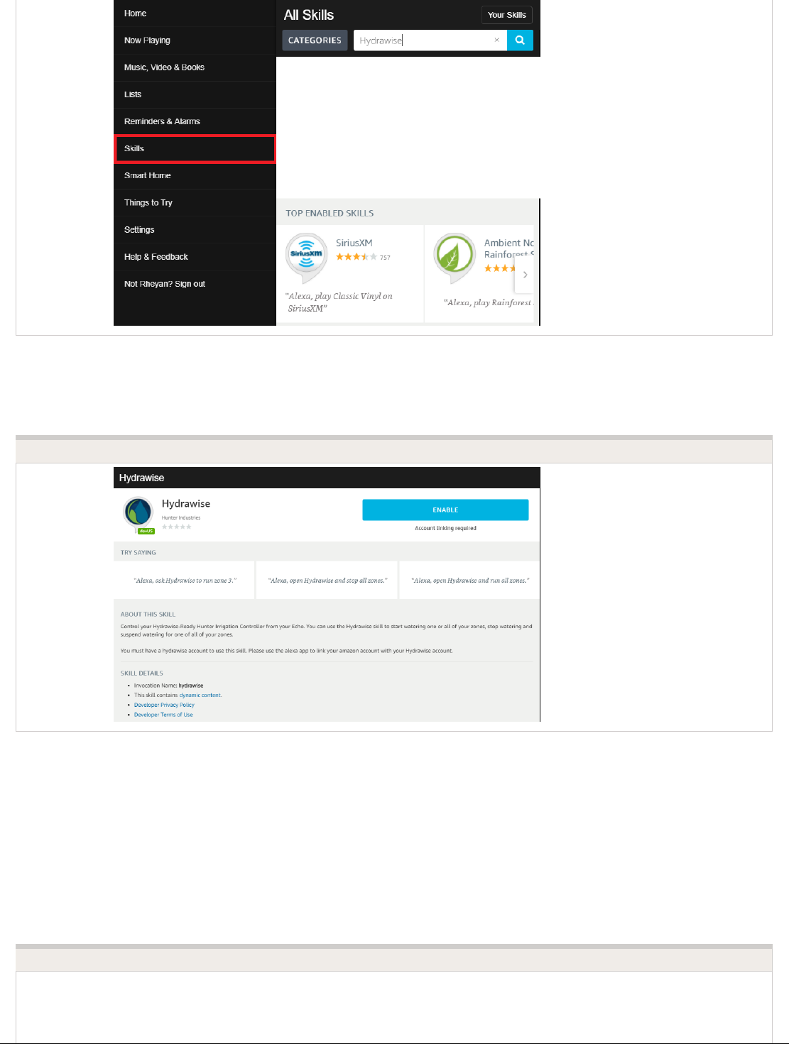
1. Click ENABLE.
ENABLE SKILL
This will open a new window where you can log in to your Hydrawise account.
IMPORTANT: Please make sure you have pop-ups enabled for the Hydrawise log-in
window. If pop-ups are blocked, you will not be able to log in and continue the linking
process.
LOG INTO HYDRAWISE
Copyright 2020 Hunter Industries. All Rights Reserved. 31

If you are already logged in, you will see the next dialogue box appear.
AUTHORIZATION REQUIRED
Copyright 2020 Hunter Industries. All Rights Reserved. 32

Click Grant permission to AWS Alexa.
You will then receive a confirmation that Hydrawise was successfully linked and you can
close the window.
SUCCESSFULLY LINKED PAGE
Using Alexa to control your Hydrawise
Zones can be started or stopped by referencing the zone number (do not use the
zone name). For example, if your Zone 1 is called “Front Garden” and you want to start it,
you can say, “Alexa, ask Hydrawise to start Zone 1.”
Alexa supports the following key phrases:
Alexa, ask Hydrawise to start/run zone {number}.
This command will start a single zone for its default irrigation time.
e.g., Alexa, ask Hydrawise to start Zone 5.
Alexa, ask Hydrawise to start/run zone {number} for {x} minutes.
This command will start a single zone for a specific time
e.g., Alexa, ask Hydrawise to run Zone 1 for 10 minutes.
Alexa, ask Hydrawise to start/run expander {expander number} zone {number}.
This command will start a single zone on controllers with expansion modules
e.g., Alexa, ask Hydrawise to start Expander 1, Zone 1.
Alexa, ask Hydrawise to start/run all zones.
This command will start all zones for their default irrigation time.
Alexa, ask Hydrawise to stop/finish zone {number}.
This command will stop a single zone if it is currently running.
Alexa, ask Hydrawise to stop/finish expander {expander number} zone {number}.
Copyright 2020 Hunter Industries. All Rights Reserved. 33

This command will stop a single zone on an expansion module.
Alexa, ask Hydrawise to suspend zone {number} until {time/date}.
This command will suspend all zones for a period of time.
Home Automation - Control4
Hydrawise is now compatible with Control4 home automation software.
Control4 installers can now download drivers to allow the integration.
From the Control4 app, you can access the following features:
View icons and zone information
View proposed watering
Manually start a zone
View active (watering) stations
NOTE: More details on Control4 integration can be found using this link: Control4 Details
[24].
Account - Translation Options
Steps to take to change language via Google Chrome
To change the language in google Chrome, please follow the steps below.
Copyright 2020 Hunter Industries. All Rights Reserved. 34

Once you have downloaded and installed Google Chrome [25], you can then change the
language to your desired language.
When you are logged in to your account, right-click anywhere along the top of the
dashboard and select Translate to English.
Once you have clicked Translate to English, the next dialogue box will appear. Click
on Options.
You will then be brought to the next two dialogue boxes:
Copyright 2020 Hunter Industries. All Rights Reserved. 35

From here, you can select the language of choice. You also have the option to
check Always Translate.
NOTE: Translation sometimes does not occur automatically when you click to navigate to another page. When
this happens, press F5 or click Refresh to refresh the page. Follow the steps again from the top to translate the
page to the language of choice.
This example shows the page translated in German:
IMPORTANT: Please keep in mind that because translations are performed by Google Chrome, there may be
some inaccuracies.
This method can also be used when going through our Help Guides [26] here on Zendesk. If
you need further assistance, email us at support@hydrawise.com.
iOS and Android App Support
Policy
Copyright 2020 Hunter Industries. All Rights Reserved. 36

The Hunter Hydrawise app’s general policy is to support Android and iOS version for as
long as the manufacturer (ie. Google or Apple) supports their operating system version.
It is important to use an Android or iOS version that is supported by Apple or Google to
ensure you have the manufacturer’s latest security updates to protect your data.
As of July 2019, Google officially supports Android 7.0 (Nougat) and above. Apple officially
supports iOS versions 12.3 and above.
While we do our best to maintain support for older versions, changes in technology mean
that sometimes it is not possible to add features to our apps whilst maintaining backward
compatibility with unsupported versions of Android or iOS.
While not supported, we do have customers using older versions of Android (eg. Android
5.0) and iOS (eg. iOS 10.0) without issues.
If your app does not work with your unsupported version of Android or iOS, it may be
possible to use your Hydrawise system via the web browser (www.hydrawise.com [20]) in the
older device.
Hydrawise Controller Efficiency
LEED
Controller Efficiency (CE) is a value that helps determine the amount of potential landscape
water savings for a LEED-certified project. CE is calculated as the percentage of potential
water savings delivered from a weather or moisture-based irrigation controller subtracted
from one (1), as reflected in the following equation: CE = 1 – (percent savings).
Hunter Industries offers three solutions that meet or exceed USGBC LEED requirements:
Solar Sync® paired with any AC-powered Hunter controller
Soil-Clik® paired with any AC-powered Hunter controller
Hydrawise™ software paired with a Hunter HC, Pro-HC, X2 with WAND, HPC, and
Copyright 2020 Hunter Industries. All Rights Reserved. 37

HCC controllers.
Since there are many variables that influence the actual percentage of water savings
delivered from a weather or moisture-based irrigation controller, it is difficult to place a
value on any specific controller. However, through in-house testing, third-party testing, and
field audits, Hunter has determined that water savings delivered from the Solar Sync, Soil-
Clik, and Hydrawise solutions typically range from 20% to 40%. This would translate to a
CE of 0.6 to 0.8. Please contact your local Hunter sales representative to learn about
additional ways to save water for your LEED-certified projects.
Setting up a Controller in Offline
Mode
Offline programming will allow your controller to run without any internet access like a
traditional irrigation controller. Hydrawise controllers have two different modes that will run
in offline mode.
Modes Controller Models
Standard Mode HPC, HCC, PRO-HC, and X2
Advanced Mode HPC, HCC, PRO-HC, and HC
Standard offline programming will allow the controller to run like our traditional controllers
the X-core and the Pro-C models. Each of the six programs (a-f) allows you to start each
program up to four times a day, set run lengths and set specific days to water.
Advanced offline programming will allow the controller to run independently for each
zone(station). Each zone (station) can have up to four start times with their individual run
times.
To set your controller in Offline Mode for manual configuration, please follow the steps
below:
1. From the main menu, tap on Settings.
2. Select Config.
3. Select Factory Default.
4. Next , press Erase Config. This will reset the controller back to factory settings. You
Copyright 2020 Hunter Industries. All Rights Reserved. 38

will be presented with a warning dialogue.
5. Select Configure Offline and follow the wizard steps.
This wizard will guide you through the steps to set up your controller to run in offline mode
without an internet connection.
If you choose to switch modes when using the compatible model, use the steps below:
1. From the main menu, tap on Settings.
2. Select Offline Programs and Settings.
3. Select Offline Mode.
4. Choose mode and select Confirm.
If you decide to connect the controller via internet at a later date, the online programming
will sync with controller within a few seconds and override the offline programming.
Offline Mode - Advanced Offline
Mode
Offline Mode
If the controller loses its internet connection for more than 24 hours, you’ll receive a
notification email. The controller will then go into offline mode. In offline mode, your
controller won’t be able to access local weather conditions such as rainfall or evaporation.
As a result, it will revert to a predefined program.
For Smart Watering zones, the controller will adjust each zone’s watering length
Copyright 2020 Hunter Industries. All Rights Reserved. 39

based on your offline watering budget and will water at each zone’s configured peak
watering frequency.
For Time-Based Watering zones, the controller will adjust each zone’s watering length
based on your offline watering budget and will water at each zone’s configured
watering frequency.
Note that Cycle and Soak is not supported in offline mode and each zone will water
for its full watering length without pausing.
The controller will only water at your configured Program Start Times.
To set your controller to Offline Mode for manual configuration, please follow the steps
below:
1. From the main menu, tap on Settings.
2. Tap on Offline Settings.
3. Tap on Disable Wi-Fi.
4. You will be presented with a warning dialogue. Please make sure you understand the
warning before proceeding. If you're sure that you want to go offline, tap Go Offline.
5. Now that your controller is in Offline Mode, you can configure it manually by tapping
on Program Start Times.
6. From this screen, you can manually configure each zone according to your desired
schedule. Simply tap on Add to add a program start time and follow the steps below.
You can toggle between zones by tapping on Next/Previous or you can leave the start
time to APPLY to ALL ZONES.
Applying the start time to ALL ZONES will run through all zones with a
single start time.
Tap ADD in the start times menu.
Select the green box upper in left to enter PROGRAM START TIME (24 hr format)
Tap the DAYS to be selected after finished with start time entry.
Tap CONFIRM to save the start time entry.
Add a second start time for all zones or single zone if desired.
Tap the HOME icon (upper right) to allow station run times setup.
NOTE: Each zone can have up to four program start times and an additional four start
times under the All Zones section as shown below.
7. From the home screen, you can manually configure each zone run time.
Simply tap on ZONES to add a zone run time and follow the steps below.
You can toggle between zones by tapping on each zone number.
Tap ZONES in the home menu.
Tap the first zone to edit, (For Example: ZONE 1).
Copyright 2020 Hunter Industries. All Rights Reserved. 40

Tap on RUN TIME in the center of the screen.
Enter RUN TIME (minutes:seconds format), then press OK to save entry.
Repeat steps 1-4 for station run times.
NOTE: To get your controller back in online mode, follow the above steps, enable Wi-Fi,
reconnect to your SSID (Wi-Fi connection), and let the controller synchronize with your
online Hydrawise account.
Copyright 2020 Hunter Industries. All Rights Reserved. 41

Offline Mode - Run the Setup
Wizard
Please follow the steps below to run the setup wizard in offline mode. Refer to Setting
Controller to Offline Mode [27] or How to Factory Reset Controller [28] before running the
wizard.
1. From the Connection Wizard screen, tap on Configure Offline. If you select OK, you
will proceed to the online setup wizard.
2. Tap OK to move on to the next step.
3. Enter in today’s date if it hasn’t already been set or if it is incorrect.
4. Enter today’s time if it hasn’t already been set or if it is incorrect.
5. From this screen, tap OK.
6. Please assign your Master Valve if you’re running one as advised on the previous
screen. Otherwise, keep Not Assigned selected and tap Confirm.
7. Tap OK.
8. You can now enter (in minutes) the run length you want for your default zone run
time. Then tap OK.
9. Tap OK to proceed to the next screen.
10. Next, set how often each zone will run. As advised on the previous screen, you can set
individual frequencies for each zone.
11. Tap on OK to proceed.
12. From this screen, you can manually configure each zone according to your desired
schedule. Simply tap on Add to add a program start time and follow the steps below.
You can toggle between zones by tapping on Next/Previous or you can leave the start
time to APPLY to ALL ZONES.
Copyright 2020 Hunter Industries. All Rights Reserved. 42

Note: Each zone can have up to four program start times and an additional four start times
under the All Zones section as shown below. Applying the start time to ALL ZONES will run
through all zones with a single start time.
1. Tap ADD in the start times menu.
2. Select the green box upper in left to enter PROGRAM START TIME (24 hr format)
3. Tap the DAYS to be selected after finished with start time entry.
4. Tap CONFIRM to save the start time entry.
5. Add a second start time for all zones or single zone if desired.
6. Tap the HOME icon (upper right) to allow station run times setup.
From the home screen, you can manually configure each zone run time. Simply tap
on ZONES to add a zone run time and follow the steps below. You can toggle between
zones by tapping on each zone number.
Note: The default run time and default watering frequency are applied to all zones during
the setup wizard. Setting individual run times and frequencies is done by going into each
zone afterwards.
1. Tap ZONES in the home menu.
2. Tap the first zone to edit, (For Example: ZONE 1).
3. Tap on RUN TIME in the center of the screen.
4. Enter RUN TIME (minutes format), then press OK to save entry.
5. Repeat steps 1-4 for station run times.
Copyright 2020 Hunter Industries. All Rights Reserved. 43

NOTE: To get your controller back in online mode, follow the above steps, enable Wi-Fi,
reconnect to your SSID (Wi-Fi connection), and let the controller synchronize with your
online Hydrawise account.
Offline Adjustments - Watering
with no Internet
If your controller loses internet connectivity for more than one day, we'll send you an email
notification. During this time, your controller will run the last synced schedule in offline
mode.
Offline watering adjustments apply when your controller is not connected to the internet
after 30 minutes.
You can access this setting from the Controller Settings tab on your home dashboard.
In offline mode, the controller will set watering times based on watering adjustments set up
beforehand.
If the next irrigation event for a zone was scheduled for Saturday, offline mode for that zone
would start after the irrigation event on Saturday if the controller didn’t have the internet. If
there are no irrigation events scheduled in the controller when it loses the internet, offline
mode will start 30 minutes after the controller loses internet.
NOTE: Without internet connectivity, your controller won't be able to automatically modify
its watering schedule based on weather forecasts.
Copyright 2020 Hunter Industries. All Rights Reserved. 44

Offline Mode - Sensors
Please follow the steps below to add and configure your sensor or flow meter in Offline
Mode. Please use the following link for Installation Instructions [29].
1. From the main menu, select Settings.
2. Next, select Offline Settings.
3. Select Sensors.
4. From this screen, you can now navigate between Sensor 1 and Sensor 2 by using the
Next and Previous options. Just as you configure your sensors online, you can select
the different options to make changes accordingly.
STEP 1
STEP 2
STEP 3
Copyright 2020 Hunter Industries. All Rights Reserved. 45

STEP 4
Sensor Status Options
Type Options Not Used, Level (Rain Sensor) or Flow Meter
Mode
Stop when open, Stop when closed, Start when open,
or Start when closed.
Status Open or Closed
Zones Applies to all zones
Active Delay Seconds
Inactive Delay Seconds
Offline Mode - Turning Off Start
Times
From the controller, you can manually turn it off by removing the start time when the
Copyright 2020 Hunter Industries. All Rights Reserved. 46

controller is NOT connected to Wi-Fi using offline mode. Please follow the steps and
screenshots listed below:
1. Select "Settings" in the home menu at the controller.
2. Select "Offline Settings."
3. Select "Program Start Times" on the upper right side of the screen.
4. Select "Modify" which will allow you to edit you start times.
5. Finally, Select "Delete" button to no longer allow controller to run in offline mode.
Step 1
Step 2
Step 3
Step 4
Copyright 2020 Hunter Industries. All Rights Reserved. 47

Step 5
Offline Mode - Seasonal Adjust
Offline water adjustments allow the controller to automatically adjust the amount of
watering on a month by month basis if the controller is in an Offline mode (ie. not
connected to the internet). Steps below will cover both online and offline instructions on
changing the seasonal adjust for when the controller enters offline mode.
Online: Offline Water Adjustment
1. Select Controller Settings on the left hand side.
2. Select Offline Adjustments.
3. Sliders can be moved to adjust the offline watering from 0%-300%.
STEP 1-2
Copyright 2020 Hunter Industries. All Rights Reserved. 48

STEP 3
Offline: Offline Water Adjustment
1. Select settings.
2. Next, select offline settings.
3. Select seasonal adjust.
4. Select a month to adjust.
5. Adjust each month by a percentage then select OK.
Copyright 2020 Hunter Industries. All Rights Reserved. 49

CONTROLLER SCREENSHOTS:
Copyright 2020 Hunter Industries. All Rights Reserved. 50

HC - Older Install Instructions
Controller Location
The Hydrawise controller is designed for installation in a protected location.
IMPORTANT: The chosen location must have Wi-Fi coverage. Wi-Fi coverage can be easily checked using an
iPhone or smartphone that has Wi-Fi connectivity, or on the Hydrawise unit itself (signal strength is shown when
you select a wireless name).
Cable Entry
The controller has two cable entry options: from the rear of the case, or via a conduit from
the bottom of the controller.
Entry from the rear of
controller
Using a sharp knife, remove the two cutouts on the rear of the controller as
indicated on the diagram in label 1.
Entry via 3/4 inch conduit
Using a sharp knife, cut around the semicircular line on the controller as
indicated on the diagram in label 2. Cut around the matching line on the blue
controller wiring cover.
Mounting the Controller
Copyright 2020 Hunter Industries. All Rights Reserved. 51

1. Using a 3/16-inch diameter drill bit, drill a hole to a depth of 1 inch (25 mm).
2. Insert plastic anchor so it is flush with the surface of the wall.
3. Screw 1-inch screw into plastic anchor, leaving the head protruding about 1/8 inch.
4. Slide the controller case over the screw head.
5. Mark your second mounting point (see label 3 in the diagram). Then remove the
controller, drill a hole, and insert a plastic anchor. Finally, slide the controller case over
the first screw head and screw it into place.
Connecting Solenoid Valves
Depending on the model you purchased, your controller has either 6 or 12 zones. For
convenience, there are three common wiring points, and any or all of them can be used.
Refer to the diagram below when connecting your solenoid valves to the controller.
Solenoid Valve Wiring
1. Take one wire from each solenoid. Twist the wires together and connect to the
COMMON (usually black) wire of your multicore irrigation cable. Hydrawise
recommends that all connections be sealed against moisture for long-term reliability.
2. Connect each of the other individual solenoid wires to a different wire in the multicore
cable and seal. Record zones against wire color for later reference.
3. Connect the common wire from the multi-strand cable (usually white) to any of the
three terminals on the controller marked COMMON.
Copyright 2020 Hunter Industries. All Rights Reserved. 52

4. Connect each of the other solenoid wires to one of the zone inputs.
5. If a master valve (sometimes labeled as MV on other controllers) is installed, this can
be connected to any spare zone, as any of the zones can be assigned as a master
valve output. The configuration of the master valve in the Hydrawise app is required.
6. Click the blue wiring cover into place to seal the controller and protect the wiring.
Connecting the Plug Pack
1. Use the plug pack supplied and connect the wires to the red AC terminal blocks on the
unit marked as 24V. The polarity of the wiring is not important.
2. Turn the power on. The power indicator will light up (see label 4 on the previous
diagram).
Connecting Sensors or Flow Meters (Optional)
Hydrawise supports most open/close contact sensor types, such as standard rain sensors
and soil moisture sensors.
1. Connect one sensor wire to COMMON on the controller.
2. Connect the Normally Closed or Normally Open wire from the sensor to SENSOR1 or
SENSOR2 on the controller, and configure in the Hydrawise app.
For full details, refer to the instructions provided with your sensor or flow meter. Instructions
for configuring the controller for a sensor are available here [30].
Troubleshooting Zone Issues
Try running a zone from the controller’s touch screen. If it works from the controller and
doesn’t work from the app, check that you have linked your controller’s serial number
to your account (see the previous section for details) and check your controller’s
wireless status.
If your old controller had a master valve (sometimes referred to as MV), you must
configure a master valve in the app and wire it to a spare zone on the controller.
Detailed instructions can be found on the Hydrawise website.
Check that your wiring is correct. If no zones start, check that your COMMON wire is
correctly cabled.
Copyright 2020 Hunter Industries. All Rights Reserved. 53

Lightning Transformers with
Controllers
Hydrawise controllers are capable of operating lighting transformers equipped with the
PXSYNC interface box. A commonly used transformer with the PXSYNC is the PX or EX
Transformer. We also offer a DX Transformer that can be controlled from a irrigation
controller via the 24 volt EXTERNAL connection built inside the controller.
Connect wires from the first PXSYNC or external ports inside the DX box to a station
output number (and the Common) on the Hydrawise controller.
PRO-C with PX SYNC Example
Important Pump/Master Valve notes:
Controller P/MV Terminal Output
HC
If a pump or master valve is in use,
the lighting transformer should not
be used in conjunction with
irrigation controller.
Single station output will operate
one at a time. Irrigation must not be
programmed for duration of the
lighting schedule.
PRO-HC
If a pump or master valve is in use,
the lighting transformer should not
be used in conjunction with
Single station output will operate at
a time. Irrigation must not be
programmed for duration of the
Copyright 2020 Hunter Industries. All Rights Reserved. 54

irrigation controller. lighting schedule.
HPC
If using PUMP or master valve, this
station output must be set to OFF in
the programming.
Single station output will operate at
a time. Irrigation must not be
programmed for duration of the
lighting schedule.
HCC
If using PUMP or master valve, this
station output must be set to OFF in
the programming.
Two station outputs will operate at
a time. Any two programs will run
simultaneously (lighting program
and irrigation program).
HPC- WRCLIK and HC Flow Meter
In the event you will need to install a flow meter and a rain sensor on the HPC controller,
please use the following instructions. The HPC controller utilizes a single SEN output so
these steps are necessary to make this work. For correct field wiring of the flow meter,
please reference the article here. [31]
NOTE: The software will only recognize the flow meter for this type of installation. The
Wireless Rain Clik will still shut down system after a rain event, but this will not reflect
anywhere in the software. The reports will not show ANY data for the rain events.
IMPORTANT: You will see alerts for underflow from the flow meter since the system will
continue to run even with the common circuit interrupted by the rain event. These alerts will
Copyright 2020 Hunter Industries. All Rights Reserved. 55
have to be ignored for this type of application. For more details on alerts, please view this
article here. [32]
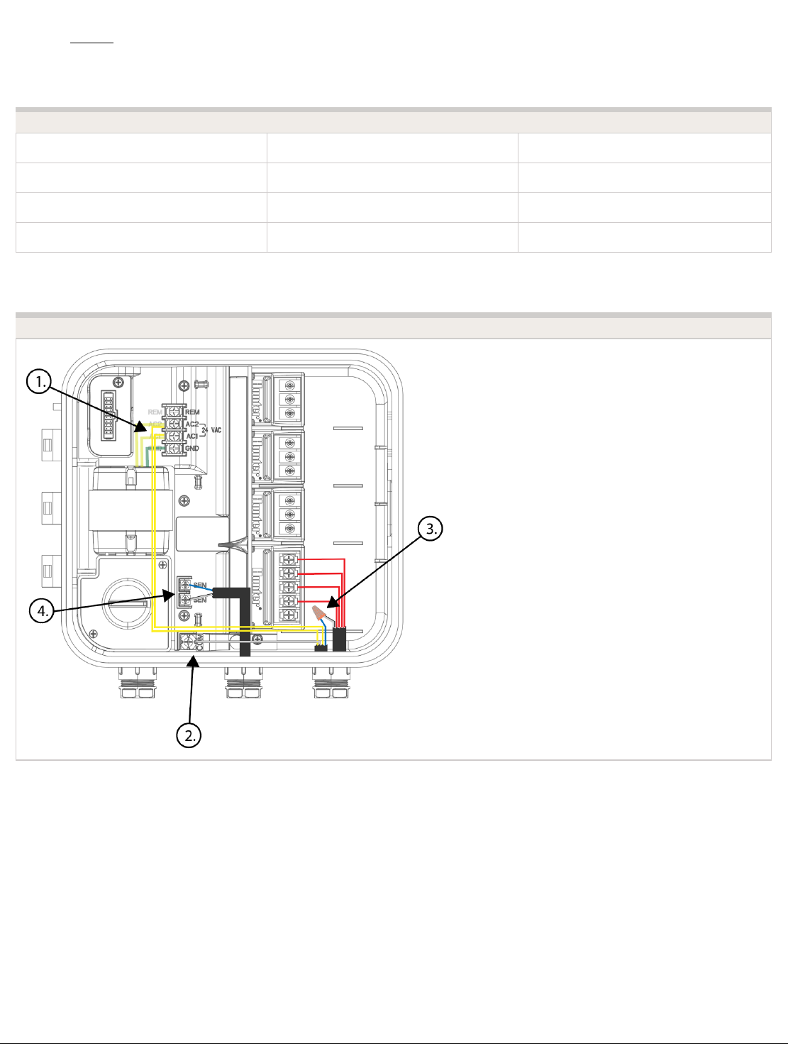
Please reference chart and illustration below for controller wiring details.
Illustration Terminals Wires
Figure 1. AC 1/ AC 2 WRCLIK Yellow
Figure 2. COMMON WRCLIK White
Figure 3. Valve Common WRCLIK Blue
Figure 4. Flow meter - Blue/White METER Blue/White
Right Click to View Larger image
Copyright 2020 Hunter Industries. All Rights Reserved. 56
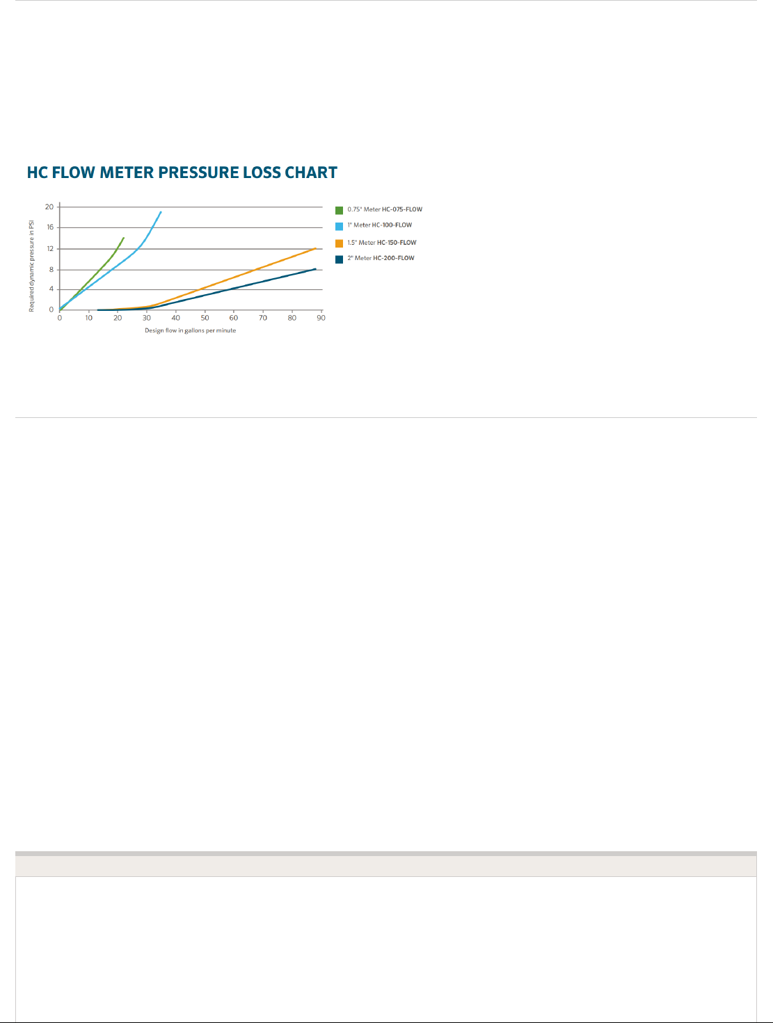
Flow Meter Pressure Loss Chart
Flow Meter - Configuration
Assigning the Meter
Please view the steps and screenshots to access this feature:
1. Click on "Sensors" from the home dashboard.
2. Add "Sensor."
3. Choose a name, sensor type, and controller input (flow related only).
4. Choose which zones should be linked to the sensor.
5. Click ok when finished.
Step 1
Copyright 2020 Hunter Industries. All Rights Reserved. 57

Step 2
Step 3
Copyright 2020 Hunter Industries. All Rights Reserved. 58

Step 4
Copyright 2020 Hunter Industries. All Rights Reserved. 59
Flow Meter - Quick Start Guide
Please click on the link below to download the flow meter connection guide.
Flow Meter - Installation Tips
Flow meters are supplied with detailed installation instructions [29].
The flow meter wires need to be cabled back to the controller and connected to the Sensor
inputs on the controller. See chart below for wiring standard Hydrawise flow meters (Sizes
include 3/4", 1", 1.5", 2")
FLOW METER WIRE SCREW TERMINAL CONTROLLER
BLUE SEN 1, 2 HC
BLUE SEN 1, 2 PRO-HC
BLUE SEN HPC-FP
WHITE COM HC
WHITE SEN COM PRO-HC
WHITE SEN HPC-FP
RED Not Used, Cap off N/A
The tips below include all the necessary key points of the install to avoid any false alerts or
readings.
Installation Steps Description
Flow meters are designed to be
installed horizontally only, with the dial facing
up. Not vertically. Analog dial for manual readings
Copyright 2020 Hunter Industries. All Rights Reserved. 60

Flow Meter Body in U.S. are shown in US gallons (Int. customers
the dial reads in Cubic Meters). Units can be
changed in App to gallons or liters.
Adapter Brass unions included to fit your irrigation system.
Entry Location
Install between the master valve and
zone valves. Meter should be installed
10 times pipe diameter before and 5
times after with straight pipe and no
fittings. See example:
Pipe 10x-Before 5x-After
3/4" 7.5" 3.75"
1" 10" 5"
1.5" 15" 7.5"
2" 20" 10"
Cable used (shielded cable only)
18 gauge - 1000 foot max Length. Shielded
direct burial cable must be used. Cable should
consist of two dedicated wires and must not be in
the same conduit, cable bundle or trench as the
solenoid wires. DO NOT share common wire.
Shielded cable is commonly available, here are
some manufacturers (Paige [33] & Regency [34]For
additional information on avoiding electrical
interference, see below:
Flow meter body Arrow indicates direction of flow.
Wire Connection
Blue/White wire only, red not used. See sensor
configuration [35] for more info based on model
controller.
Log in to your account Enter your login [15] information.
Create your flow sensor App will show options for all HC meters.
Creating Alerts See link here [36]
Reading Meter See link here [37]
Testing Meter See link here [38]
Avoid Electrical Interference
Copyright 2020 Hunter Industries. All Rights Reserved. 61

Always use shielded cable, between the controller and the HC Flow Meter.
At the controller end, using the shield (foil wrap) and the bare wire connect them to the
controller GND terminal (not required for HC controllers).
Do not connect the other end of the Shield or the bare wire to the Earth or a grounding
stake
Use Waterproof wire connectors at the flow meter, such as the 3M-DBOB [39].
Shielded cable is commonly available, here are some manufacturers. Paige [33] &
Regency [34]
In the event you continue to receive bad readings or false alerts, please contact
us support@hydrawise.com [8]
Flow Meter - Specifications
HC FLOW METER SPECIFICATIONS
HC-075-FLOW
(¾")
HC-100-FLOW
(1")
HC-150-FLOW
(1½")
HC-200-FLOW (2")
Inlet/outlet ¾" NPT body, 1" NPT body, male 1½" NPT body, 2" NPT body, male
Copyright 2020 Hunter Industries. All Rights Reserved. 62

connection size male thread thread male thread thread
Meter internal
diameter
3/4" 1" 1.5" 2"
Minimum flow (GPM) 0.22 0.3 0.88 1.98
Maximum
recommended flow
(GPM)
15 30 66 105
Maximum flow rate
(GPM)
21 34 88 132
Dial reading (US gal)
1 pulse per 0.1
U.S. gal
1 pulse per 1 U.S.
gal
1 pulse per 1 U.S.
gal
1 pulse per 1 U.S.
gal
Maximum working
pressure (PSI)
230 230 230 230
Flow Meter - Reading Meter
The Hydrawise flow meters come in a US Gallon reading for domestic and metric reading
called M³ (Meters Cubed 1000 Liters) for international. Conversion rate for metric meters is
3.78 Liters to 1 US Gallon if required.
See example of meter reading below in US gallons:
Fig. 1 X100 8100 Gallons
Fig. 2 X10 814X.XX Gallons
Fig. 3 X1 8142.XX Gallons
Fig. 4 X0.1 8142.4X Gallons
Fig. 5 X0.01 8142.46 Gallons Total
Fig. 6 Size meter 1"
Fig. 7 Flow Indicator Wheel spins when water is flowing.
Copyright 2020 Hunter Industries. All Rights Reserved. 63

We have a flow that has gone through the meter of 8,142.46 gallons.
See example of meter reading below in Litres:
Fig. 1 8,000 Litres
Fig. 2 8,200 Litres
Fig. 3 8,220 Litres
Fig. 4 8,224 Litres
Fig. 5 8,224.7 Litres Total
Fig. 6 Wheel spins when water is flowing.
So we have a flow that has gone through the meter of 8,224.7 Litres. To calculate this into
Gallons is easy 8,224.7 / 3.78 = 2175.84 gallons.
Copyright 2020 Hunter Industries. All Rights Reserved. 64

Flow Meter - Testing Meter
If your flow meter is working but is not recording data in your Dashboard or events, follow
the steps here:
1. Make sure sensor is configured [40] in the software.
2. Make sure controller is online. If not, please use link [41] for Wi-Fi troubleshooting steps.
3. Remove the wire splices at the flow meter connection in the field. Tap the two wires
together that run to the controller 10 times, as each contact will record a pulse.
Refresh the app to see if the flow usage was registered.
4. If app registered flow usage, your wiring and system are set up correctly. Reconnect to
the flow meter and run a large flow (lots of sprinklers) zone. Did you get a flow on your
app? If YES, all is OK. If NO, contact support@hydrawise.com [42].
5. If app did not register flow usage, test the sensor inputs on the controller. You can use
the same method with a paper clip or wire to make contact between sensor 1 or 2 and
the common terminal. Do this 10 times and then check for flow data usage at the home
screen. If YES, there is a problem with the wire running to the flow meter. If NO,
contact support@hydrawise.com [42].
Copyright 2020 Hunter Industries. All Rights Reserved. 65

IMPORTANT: Our controller is not polarity sensitive. There is no risk of electric shock when performing these
tests. However, if you feel uncomfortable, please contact a qualified technician or irrigation specialist for further
assistance.
NOTE: If it works at the controller end but not the flow-meter end, there is a wiring fault.
If it doesn't work at the controller end, contact support@hydrawise.com [42].
If it works at both ends, but still does not register flow on the app, contact support@hydrawise.com [42].
Flow Meter - Custom Flow Sensor
Configuration
To add a custom flow sensor, go to Sensors [43] from your web browser or smartphone
application.
1. Click Add Custom Sensor Type
STEP 1
Copyright 2020 Hunter Industries. All Rights Reserved. 66

A dialogue box will appear for you to enter your custom flow meter details. Make sure you
enter the calibration details for your custom pulse-based flow meter. Please refer to the
manufacturer specifications to find out the calibration. Otherwise, you will not get accurate
readings to display on your flow data.
NOTE: For our system to detect the correct flow data and reflect it on your Dashboard reports, any third-party
flow meter used must be a true pulse flow meter or have a reed switch. We aim for a minimum of 10 pulses per
min and a maximum of 120 pulses per min. That means if the flow rate was 10 gal per min, 1 pulse per gallon
needs to be set.
When using a third-party flow meter, please ensure it meets the specs above and is
calibrated correctly. Otherwise, data will not reflect accurately in reports. Also, note that the
Copyright 2020 Hunter Industries. All Rights Reserved. 67

wiring is not polarity sensitive. As long as you have one wire in a Sensor Port and a
Sensor Common, the device will work correctly. For flow meters that use three wires and
meet the specs above, configure the wiring until you find the two correct wires to use.
Single Flow Meter - Sharing Two
Controllers
For this installation, we suggest a few tips to make sure you do not receive any
unnecessary alerts.
When using multiple controllers on the same flow meter, there are two alerts we do not
recommend using.
1. High Flow Leak - High water usage with no zones running.
2. Slow Leak - Water usage over last hour with no zones running.
These alerts are controller specific so when the controller with the flow meter is not in
operation, it does know about the other controller operation.
Tips:
1. The inter station delay [44] should be set for 10-30 seconds. We do not recommend any
higher.
2. Change the gallons in the alert to be higher (e.g. alert from 5 gallons to 20 gallons).
Following these parameters should allow the system to run normal when using one flow
meter with multiple controllers.
Copyright 2020 Hunter Industries. All Rights Reserved. 68

Flow Meter - Winterization
We recommend that a qualified licensed contractor perform this type of winterization
method. The blowout method utilizes an air compressor with a cubic foot per minute (CFM)
rating of 80-100 for any mainline of 2" or less. The compressor is attached to the mainline
via a quick coupler, hose bib, or other type connection, which is located beyond the
backflow device. Compressed air should not be blown through any backflow or flow meter
device. For additional winterization procedures, we highly recommend contacting the local
dealer for the most common local practices. In the event you need to blow upstream from
where the flow meter is located, we recommend bypassing the meter by temporarily using
one of two options.
1. Installing a SCH 80 or galvanized nipple. See the size chart below:
Winterizing Using PVC Nipple Bypass Option
Model Description
Male-Thread
NPT
Nipple Length
Copyright 2020 Hunter Industries. All Rights Reserved. 69

HC-075-FLOW
¾" NPT body, male thread with 1"
NPT male adapter
1" NPT 5"
HC-100-FLOW
1" NPT body, male thread with 1.5"
NPT male adapter
1 ¼"NPT 5"
HC-150-FLOW
1½" NPT body, male thread with 2"
NPT male adapter
2"NPT 11 3/4"
HC-200-FLOW
2" NPT body, male thread with 3"
NPT male adapter
2 1/2"BSP 11 3/4"
2. A second option would be to install PVC tee diverters but this is done more efficiently
during NEW installation.
Winterizing Using PVC Diverter Option
Find a Hunter Distributor closest to you using our interactive lookup - Get Hunter [45]
Copyright 2020 Hunter Industries. All Rights Reserved. 70

Pump Start Relay Wiring and
Online Setup
In this article, we will discuss the following topics:
Summary
Operation Chart
Wiring (24 VAC)
Wiring to Power Source
Online Setup
Pump Start Relay Operation per Zone
Summary
When a system requires the use of a booster pump or pulls water directly from a creek or
pond, it’s imperative to include a relay to activate the pump each and every time. A pump
start relay is a relay box that activates a pump every time a zone is activated from the
controller. Zone valves are the individual valves that operate a group of sprinklers or drip
emitters. Hydrawise controllers support 6- to 54-zone valves, depending on the model.
Typically, one zone valve is turned on at a time and controls the irrigation in a specific area
of your landscape. Whenever one of the irrigation zone valves is told to open by the
controller, the controller also signals the pump start relay to turn the pump on.
Operation Chart
Controller Model Set Pump Operation
HC ON or OFF by All Zones
PRO-HC ON or OFF by All Zones
HPC ON or OFF by Zone or All Zones
HCC ON or OFF by Zone or All Zones
Wiring (24 VAC)
Use a minimum distance of 15' (4.5 m) between the controller and the relay to dampen
electromagnetic noise. In addition to this recommendation, Hunter also recommends all
Copyright 2020 Hunter Industries. All Rights Reserved. 71

controllers be mounted 15' (4.5 m) away from pumps and high-voltage devices.
1. Detach the pump start relay cover plate by removing the four screws with
Phillips screwdriver.
2. Run a single wire from the "common" terminal on the controller to one of the yellow
wires on the pump start relay.
3. Run a single wire from the "P/MV" terminal on the controller to the other yellow wire on
the pump start relay.
4. Use wire nuts to make the connections and verify they are secure.
5. Install pump start relay cover plate and four screws. Close and lock the cabinet door.
6. Route wire through the conduit or one of the openings on the bottom of the cabinet.
7. Strip ½" (13 mm) of insulation from the ends of all wires. Secure the valve common
wire to “COM” (Common) terminal. Attach the opposite control wire to the M/V terminal.
Pump Start Relay Maximum Wire Lengths
MAXIMUM one-way wire length (do not go this far!)
Model 18 AWG 16 AWG 14 AWG 12 AWG 10 AWG 8 AWG
PSR-22 243 ft 386 ft 616 ft 976 ft 1,551 ft 2,463 ft
PSR-52 134 ft 214 ft 341 ft 540 ft 859 ft 1,365 ft
PSR-53 134 ft 214 ft 341 ft 540 ft 859 ft 1,365 ft
HC PRO-HC
HPC HCC
Copyright 2020 Hunter Industries. All Rights Reserved. 72

Note: With an HC Hydrawise controller, any one of your 6 or 12 zones can be configured
to act as the pump start relay. We usually recommend wiring to the last zone that is not
being used in the controller.
Wiring to Power Source
NOTE: Connecting the pump start relay should only be done by a licensed electrician
following local codes. Improper installation could result in shock or fire hazard.
1. To prevent electric shock, turn the main circuit-breaker switch to “off” prior to making
electrical connections.
2. Assemble conduit piping and connect AC power from the power source to one side
(LINE IN) of the relay.
3. Assemble conduit piping and connect wiring from the pump motor to the other side of
the relay (LOAD OUT).
4. Check to make sure there are no exposed or loose connections.
Copyright 2020 Hunter Industries. All Rights Reserved. 73

Online Setup
This setup option is prompted when you first go through the initial setup wizard in the
software.
The online instructions will refer to a master valve but this same setting applies when
using a pump start relay.
Note: With an HC Hydrawise controller, any one of your 6 or 12 zones can be configured
to act as the pump start relay. We usually recommend wiring to the last zone that is not
being used in the controller.
Does your irrigation system have a master valve?
If you need to change this in the software after the setup wizard, refer to the instructions
below.
1. Log in to your Hydrawise account
2. Click on Zones and Schedules for the PC or Zones if using the mobile app.
3. Choose YES from the drop-down menu above the zones. If you have an HC controller,
choose the zone number to which you have the master valve wired.
HC Controller PRO-HC, HPC, and HCC Controllers
Copyright 2020 Hunter Industries. All Rights Reserved. 74

Pump Start Relay Operation per Station
When selecting a pump start relay to be on/off for an individual zone, you can edit the
zone in Zones and Schedules under Advanced Settings. This option is useful when one
zone is using city water and another is using water from a different source.
Note: This option is for HPC and HCC controllers only.
Follow the steps below to change this setting:
1. From the Zones and Schedules page, click on the icon on the zone you would like
to edit.
2. Click on Advanced, which is located on the top blue search section.
3. Select Use Global Master Valve Setting to keep this circuit on or select Disable
Master Valve to turn it off.
Copyright 2020 Hunter Industries. All Rights Reserved. 75

One Master Valve - Two
Controllers
There are many times when two controllers are being supplied from a single POC (point of
connection) or source of water. Hydrawise-ready controllers can be connected to a single
master valve using a isolation relay (part number REL2). This device will allow for two
controllers to share the same master valve with out any issues.
The few limitations include:
Only one controller can operate at a time.
A delay of at least five minutes between the operation of controller #1 and controller #2
is desirable.
Electrical alerts will apply for each controller.
Steps for set up.
1. Wire the relay according to the drawing below.
2. Set up the master valve in the the app for both controllers using the normal instructions
in the article here [46].
3. Set up a new master valve using the app for controller #2 as per normal instructions.
REL 2 is NEVER connected to high voltage. It is for 24 VAC devices only.
Copyright 2020 Hunter Industries. All Rights Reserved. 76

Master Valve Wiring and Online
Setup
In this article, we will discuss the following topics:
Brief Summary
Operation Chart
Wiring
Setup Online
Master Valve (P/MV) Operation per zone
Brief Summary
A master valve is a normally closed valve installed at the supply point of the main line that
opens only when the automatic system is activated. Zone valves are the individual valves
that operate a group of sprinklers or drip emitters. Hydrawise controllers support 6 - 54
zone valves, depending on the model. Typically one zone valve is turned on at a time and
controls the irrigation in a specific area of your garden. Whenever one of the irrigation zone
valves is told to open by the controller, the controller also signals the master valve to open.
The purpose of the master valve is to shut off the water to the irrigation system when none
of the zone valves are operating.
Operation Chart
Controller Model Set Master Valve Operation
HC ON or OFF by All Zones
PRO-HC ON or OFF by All Zones
Copyright 2020 Hunter Industries. All Rights Reserved. 77

HPC ON or OFF by Zone or All Zones
HCC ON or OFF by Zone or All Zones
Wiring
1. Route the master valve wire between valve location and Hydrawise controller.
2. Attach the common wire to either solenoid wire. This is most commonly a white colored
wire. Attach a separate control wire to the remaining wire of each master valve
solenoid. All wire splice connections should be done using waterproof connectors.
3. Route wire through the conduit or one of the openings on the bottom of the cabinet.
4. Strip ½" (13 mm) of insulation from ends of all wires. Secure the valve common wire to
“COM” (Common) terminal. Attach the opposite control wire to the M/V terminal.
HC PRO-HC
HPC HCC
Note: With a HC Hydrawise controller, any one of your 6 or 12 zones can be configured to
Copyright 2020 Hunter Industries. All Rights Reserved. 78

act as a master valve. We usually recommend wiring to the last zone not used in the
controller.
Setup Online
This setup option is prompted when you first go through the initial setup wizard in the
software.
Does your irrigation system have a Master Valve?
In the event you need to change this in the software after the setup wizard, please refer to
the instructions below.
1. Login to your Hydrawise account
2. Click on Zones and Schedules for the PC or Zones if using the mobile app.
3. Choose YES from the drop down above the zones. If you have an HC controller, then
you choose the zone number that you have the master valve wired too.
HC Controller PRO-HC, HPC, and HCC Controllers
Copyright 2020 Hunter Industries. All Rights Reserved. 79

Master Valve (P/MV) Operation per Station
For selecting a master valve to be on/off for a individual zone, this can be done when
editing the zone in zones and schedules under advanced settings. This option is useful
when one zone is using city water and another is using from another source.
Note: This option is for HPC and HCC controllers only.
Please follow the steps below to change this setting.
1. From the Zones and Schedules page, click on the icon on the zone you would like
to edit.
2. Click on Advanced located on the top blue search section.
3. Select Use Global Master Valve Setting to keep this circuit on or select Disable
Master Valve to turn this circuit off.
Valve - Wire Distance
Below is a chart indicating the maximum wire run between the controller and the Hunter AC
Copyright 2020 Hunter Industries. All Rights Reserved. 80

solenoid valves.
Valve Wire Sizing (Feet)
Ground Control Wire
18 16 14 12 10 8 6
18 850 1040 1210 1350 1460 1540 1590
16 1040 1340 1650 1920 2150 2330 2440
14 1210 1650 2150 2630 3080 3450 3700
12 1350 1920 2630 3390 4170 4880 5400
10 1460 2150 3080 4170 5400 6670 7650
8 1540 2330 3450 4880 6670 8700 10530
6 1590 2440 3700 54000 7690 10530 13330
Notes:
Maximum one-way distance in feet between controller and valve heavy-duty solenoid: 24
VAC, 350 mA inrush current, 190 mA holding current, 60 Hz; 370 mA inrush current, 210
mA holding current, 50 Hz
Valve Wire Sizing (Metric)
Ground Control Wire
0.5 1 1.5 2.5 4 6
0.5 140 190 210 235 250 260
1.0 190 290 335 415 465 495
1.5 208 335 397 515 595 647
2.5 235 415 515 730 900 1030
4.0 250 465 595 900 1175 1405
6.0 260 495 647 1030 1405 1745
Notes:
Maximum one-way distance in meters between controller and valve Heavy-duty solenoid:
24 VAC,
350 mA inrush current, 190 mA holding current, 60 Hz; 370 mA inrush current, 210 mA
holding current, 50 Hz
Copyright 2020 Hunter Industries. All Rights Reserved. 81

Copyright 2020 Hunter Industries. All Rights Reserved. 82
