
CHAP.
71
BLOCK
DIAGRAM
ALGEBRA
AND
TRANSFER FUNCTIONS OF
SYSTEMS
157
Fig.
7-6

158
BLOCK DIAGRAM ALGEBRA
AND
TRANSFER FUNCTIONS
OF
SYSTEMS
[CHAP.
7
Fig.
7-6
Continued
7.6
UNITY
FEEDBACK
SYSTEMS
Definition
7.7:
A
unity
feedback
system
is one in which the primary feedback
b
is
identically equal
to the controlled output
c.
EXAMPLE
7.6.
H
=
1
for a linear,
unity
feedback
system
(Fig.
7-7).
Fig.
7-7
Any feedback system with only linear time-invariant elements can be put into the form of a unity
feedback system by using Transformation
5.
EXAMPLE 7.7.
Fig.
7-8
CHAP. 71
BLOCK DIAGRAM ALGEBRA AND TRANSFER FUNCTIONS OF SYSTEMS
159
The characteristic equation for the unity feedback system, determined from
1
&
G
=
0,
is
DG$NG=O
(7.7)
where
DG
is the denominator and
NG
the numerator of
G.
7.7
SUPERPOSITION
OF
MULTIPLE INPUTS
Sometimes it is necessary to evaluate system performance when several inputs are simultaneously
applied at different points of the system.
When multiple inputs are present in a
linear
system, each is treated independently of the others.
The output due to all stimuli acting together is found in the following manner. We assume zero initial
conditions, as we seek the system response only to inputs.
Step
1:
Set all inputs except one equal to zero.
Step
2
Transform the block diagram to canonical form, using the transformations of Section
7.5.
Step
3:
Calculate the response due to the chosen input acting alone.
Step
4:
Repeat Steps
1
to
3
for each of the remaining inputs.
Step
5:
Algebraically add all of the responses (outputs) determined in Steps
1
to
4.
This sum is the
total output of the system with all inputs acting simultaneously.
We reemphasize here that the above superposition process is dependent on the system being linear.
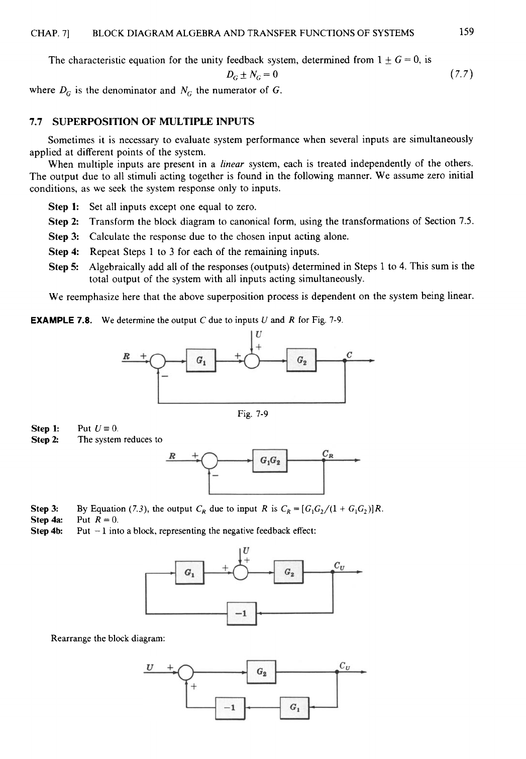
EXAMPLE
7.8.
We determine the output
C
due to inputs
U
and
R
for Fig. 7-9.
Fig. 7-9
Step 1:
Step
2
Put
U
= 0.
The system reduces to
Step
3:
Step4a:
Put
R=0.
Step 4b
By Equation
(7.3),
the output
C,
due to input
R
is
C,
=
[G1G2/(1
+
GlG2)]R.
Put
-
1
into a block, representing the negative feedback effect:
Rearrange the block diagram:

160
BLOCK DIAGRAM ALGEBRA
AND
TRANSFER FUNCTIONS OF
SYSTEMS
[CHAP.
7
Let the
-
1
block be absorbed into
the
summing point:
Step
4c
Step
5:
By
Equation
(7.3),
the output
C,
due to input
U
is
C,
=
[G2/(1
+
G1G2)]U.
The total output is
C=C,+C,=
[
~
1
+G2G2]
+
[
A]
=
[
A]
IGIR
+
7.8 REDUCTION
OF COMPLICATED
BLOCK DIAGRAMS
The block diagram of a practical feedback control system is often quite complicated. It may include
several feedback or feedforward loops, and multiple inputs. By means of systematic block diagram
reduction, every multiple loop linear feedback system may be reduced to canonical form. The
techniques developed in the preceding paragraphs provide the necessary tools.
The
following general steps may be used as
a
basic approach in the reduction of complicated block
diagrams. Each step refers to specific transformations listed in Fig. 7-6.
Step
1:
Combine all cascade blocks using Transformation
1.
Step
2
Combine all parallel blocks using Transformation
2.
Step
3:
Eliminate all minor feedback loops using Transformation
4.
Step
4:
Shift summing points to the left and takeoff points to the right of the major loop, using
Step
5:
Repeat StepsJ to
4
until the canonical form has been achieved for a particular input.
Step
6
Repeat Steps
1
to
5
for each input, as required.
Transformations
3,
5,
6,
8,
9,
and
11
are sometimes useful, and experience with the reduction
Transformations 7, 10, and 12.
technique will determine their application.
EXAMPLE
7.9.
Let us reduce the block diagram (Fig. 7-10) to canonical form.
Step
1:
Fig.
7-10

CHAP.
71
BLOCK
DIAGRAM
ALGEBRA
AND TRANSFER FUNCTIONS OF
SYSTEMS
Step
2
161
Step
3:
Step
4: Does
not apply.
Step
5
Step
6
Does
not apply.
An occasional requirement of block diagram reduction is the isolation of a particular block in a
feedback or feedforward loop.
This
may be desirable to more easily examine the effect of a particular
block on the overall system.
Isolation of a block generally may be accomplished by applying the same reduction steps to the
system, but usually in a different order. Also, the block to be isolated cannot be combined with any
others.
Rearranging Summing Points (Transformation
6)
and Transformations
8,
9,
and
11
are especially
useful for isolating blocks.
EXAMPLE
7.10.
Steps
1
and
2
Let us reduce the block diagram
of
Example
7.9,
isolating block
HI.

162
BLOCK DIAGRAM ALGEBRA AND TRANSFER FUNCTIONS OF SYSTEMS
[CHAP.
7
We do not apply Step
3
at this time, but go directly to Step
4,
moving takeoff point
1
beyond block
G2
+
G,:
We may now rearrange summing points
I
and
2
and combine the cascade blocks in the forward loop using
Transformation
6,
then Transformation
1:
Step
3:
Finally, we apply Transformation
5
to remove
l/(G2
+
G,)
from the feedback loop:
Note that the same result could have been obtained after applying Step
2
by moving takeoff point
2
ahead
of
G2
+
G3,
instead of takeoff point
I
beyond
G2
+
G,.
Block
G2
+
G,
has the same effect on the control ratio
C/R
whether it directly follows
R
or directly precedes
C.
