
ETSI TS 133 310
V16.5.0 (2020-11)
Universal Mobile Telecommunications System (UMTS);
LTE;
5G;
Network Domain Security (NDS);
Authentication Framework (AF)
(3GPP TS 33.310 version 16.5.0 Release 16)
TECHNICAL SPECIFICATION

ETSI
ETSI TS 133 310 V16.5.0 (2020
-
11)
1
3GPP TS 33.310 version 16.5.0 Release 16
Reference
RTS/TSGS-0333310vg50
Keywords
5G,LTE,SECURITY,UMTS
ETSI
650 Route des Lucioles
F-06921 Sophia Antipolis Cedex - FRANCE
Tel.: +33 4 92 94 42 00 Fax: +33 4 93 65 47 16
Siret N° 348 623 562 00017 - NAF 742 C
Association à but non lucratif enregistrée à la
Sous-Préfecture de Grasse (06) N° 7803/88
Important notice
The present document can be downloaded from:
http://www.etsi.org/standards-search
The present document may be made available in electronic versions and/or in print. The content of any electronic and/or
print versions of the present document shall not be modified without the prior written authorizatio
n of ETSI. In case of any
existing or perceived difference in contents between such versions and/or in print, the prevailing version of an ETSI
deliverable is the one made publicly available in PDF format at www.etsi.org/deliver.
Users of the present document should be aware that the document may be subject to revision or change of status.
Information on the current status of this and other ETSI documents is available at
https://portal.etsi.org/TB/ETSIDeliverableStatus.aspx
If you find errors in the present document, please send your comment to one of the following services:
https://portal.etsi.org/People/CommiteeSupportStaff.aspx
Copyright Notification
No part may be reproduced or utilized in any form or by any means, electronic or mechanical, including photocopying
and microfilm except as authorized by written permission of ETSI.
The content of the PDF version shall not be modified without the written authorization of ETSI.
The copyright and the foregoing restriction extend to reproduction in all media.
© ETSI 2020.
All rights reserved.
DECT™, PLUGTESTS™, UMTS™ and the ETSI logo are trademarks of ETSI registered for the benefit of its Members.
3GPP™
and LTE™ are trademarks of ETSI registered for the benefit of its Members and
of the 3GPP Organizational Partners.
oneM2M™ logo is a trademark of ETSI registered for the benefit of its Members and
of the oneM2M Partners.
GSM
®
and the GSM logo are trademarks registered and owned by the GSM Association.

ETSI
ETSI TS 133 310 V16.5.0 (2020
-
11)
2
3GPP TS 33.310 version 16.5.0 Release 16
Intellectual Property Rights
Essential patents
IPRs essential or potentially essential to normative deliverables may have been declared to ETSI. The information
pertaining to these essential IPRs, if any, is publicly available for ETSI members and non-members, and can be found
in ETSI SR 000 314: "Intellectual Property Rights (IPRs); Essential, or potentially Essential, IPRs notified to ETSI in
respect of ETSI standards", which is available from the ETSI Secretariat. Latest updates are available on the ETSI Web
server (https://ipr.etsi.org/).
Pursuant to the ETSI IPR Policy, no investigation, including IPR searches, has been carried out by ETSI. No guarantee
can be given as to the existence of other IPRs not referenced in ETSI SR 000 314 (or the updates on the ETSI Web
server) which are, or may be, or may become, essential to the present document.
Trademarks
The present document may include trademarks and/or tradenames which are asserted and/or registered by their owners.
ETSI claims no ownership of these except for any which are indicated as being the property of ETSI, and conveys no
right to use or reproduce any trademark and/or tradename. Mention of those trademarks in the present document does
not constitute an endorsement by ETSI of products, services or organizations associated with those trademarks.
Legal Notice
This Technical Specification (TS) has been produced by ETSI 3rd Generation Partnership Project (3GPP).
The present document may refer to technical specifications or reports using their 3GPP identities. These shall be
interpreted as being references to the corresponding ETSI deliverables.
The cross reference between 3GPP and ETSI identities can be found under http://webapp.etsi.org/key/queryform.asp.
Modal verbs terminology
In the present document "shall", "shall not", "should", "should not", "may", "need not", "will", "will not", "can" and
"cannot" are to be interpreted as described in clause 3.2 of the ETSI Drafting Rules (Verbal forms for the expression of
provisions).
"must" and "must not" are NOT allowed in ETSI deliverables except when used in direct citation.

ETSI
ETSI TS 133 310 V16.5.0 (2020
-
11)
3
3GPP TS 33.310 ver
sion 16.5.0 Release 16
Contents
Intellectual Property Rights ................................................................................................................................ 2
Legal Notice ....................................................................................................................................................... 2
Modal verbs terminology .................................................................................................................................... 2
Foreword ............................................................................................................................................................. 6
Introduction ........................................................................................................................................................ 6
1 Scope ........................................................................................................................................................ 7
2 References ................................................................................................................................................ 7
3 Definitions and abbreviations ................................................................................................................. 10
3.1 Definitions ........................................................................................................................................................ 10
3.2 Abbreviations ................................................................................................................................................... 10
4 Introduction to Public Key Infrastructure (PKI) .................................................................................... 11
4.1 Manual Cross-certification ............................................................................................................................... 11
4.2 Cross-certification with a Bridge CA ............................................................................................................... 11
5 Architecture and use cases of the NDS/AF ............................................................................................ 11
5.1 PKI architecture for NDS/AF ........................................................................................................................... 12
5.1.1 General architecture .................................................................................................................................... 12
5.1.1.1 NDS/IP case .......................................................................................................................................... 12
5.1.1.2 TLS case ................................................................................................................................................ 13
5.2 Use cases .......................................................................................................................................................... 14
5.2.1 Operator Registration: Creation of interconnect agreement ....................................................................... 14
5.2.2 Establishment of secure communications ................................................................................................... 16
5.2.2.1 NDS/IP case .......................................................................................................................................... 16
5.2.2.1.1 NDS/IP case for the Za interface ........................................................................................................... 16
5.2.2.1.2 NDS/IP case for the Zb-interface .......................................................................................................... 16
5.2.2.2 TLS case ................................................................................................................................................ 17
5.2.3 Operator deregistration: Termination of interconnect agreement ............................................................... 18
5.2.3a Interconnection CA registration .................................................................................................................. 18
5.2.3b Interconnection CA deregistration .............................................................................................................. 18
5.2.3c Interconnection CA certification creation ................................................................................................... 18
5.2.3d Interconnection CA certification revocation ............................................................................................... 19
5.2.3e Interconnection CA certification renewal ................................................................................................... 19
5.2.4 SEG/TLS CA registration ........................................................................................................................... 19
5.2.5 SEG/TLS CA deregistration ....................................................................................................................... 19
5.2.6 SEG/TLS CA certificate creation ............................................................................................................... 19
5.2.7 SEG/TLS CA certificate revocation ........................................................................................................... 20
5.2.8 SEG/TLS CA certificate renewal ................................................................................................................ 20
5.2.9 End entity registration ................................................................................................................................. 20
5.2.9.1 SEG registration .................................................................................................................................... 20
5.2.9.2 TLS client registration ........................................................................................................................... 20
5.2.9.3 TLS server registration .......................................................................................................................... 20
5.2.9.4 NE registration ...................................................................................................................................... 21
5.2.10 End entity deregistration ............................................................................................................................. 21
5.2.10.1 SEG deregistration ................................................................................................................................ 21
5.2.10.2 TLS client deregistration ....................................................................................................................... 21
5.2.10.3 TLS server deregistration ...................................................................................................................... 21
5.2.10.4 NE deregistration .................................................................................................................................. 21
5.2.11 End entity certificate creation ..................................................................................................................... 21
5.2.12 End entity certificate revocation ................................................................................................................. 21
5.2.13 End entity certificate renewal ..................................................................................................................... 21
5.2.14 NE CA deregistration.................................................................................................................................. 21
5.2.15 NE CA certification creation ...................................................................................................................... 21
5.2.16 NE CA certificate revocation ...................................................................................................................... 22
ETSI
ETSI TS 133 310 V16.5.0 (2020
-
11)
4
3GPP TS 33.310 version 16.5.0 Release 16
5.2.17 NE CA certificate renewal .......................................................................................................................... 22
6 Profiling .................................................................................................................................................. 22
6.1 Certificate profiles ............................................................................................................................................ 22
6.1.1 Common rules to all certificates ................................................................................................................. 22
6.1.2 Interconnection CA Certificate profile ....................................................................................................... 23
6.1.3 SEG Certificate profile ............................................................................................................................... 24
6.1.3a TLS entity certificate profile ....................................................................................................................... 24
6.1.3b NE Certificate profile.................................................................................................................................. 25
6.1.3c SBA Certificate profile ............................................................................................................................... 25
6.1.3c.1 Introduction ........................................................................................................................................... 25
6.1.3c.2 General SBA Certificate profile ............................................................................................................ 25
6.1.3c.3 NF Certificate profile ............................................................................................................................ 25
6.1.4 SEG CA certificate profile .......................................................................................................................... 27
6.1.4a TLS client/server CA certificate profile ...................................................................................................... 27
6.1.4b NE CA certificate profile ............................................................................................................................ 28
6.1a CRL profile ...................................................................................................................................................... 28
6.2 IKE negotiation and profiling ........................................................................................................................... 28
6.2.1 Void ............................................................................................................................................................ 29
6.2.1b IKEv2 profile .............................................................................................................................................. 29
6.2.2 Potential interoperability issues .................................................................................................................. 29
6.2a TLS profiling .................................................................................................................................................... 29
6.2a.1 TLS profile.................................................................................................................................................. 30
6.2a.2 Potential interoperability issues .................................................................................................................. 30
6.3 Path validation .................................................................................................................................................. 30
6.3.1 Path validation profiling ............................................................................................................................. 30
7 Detailed description of architecture and mechanisms ............................................................................ 30
7.1 Repositories ...................................................................................................................................................... 30
7.2 Life cycle management .................................................................................................................................... 33
7.3 Cross-certification ............................................................................................................................................ 34
7.4 Revoking a SEG/TLS CA cross-certificate ...................................................................................................... 34
7.5 Establishing secure connections between NDS/IP end entities using IKE on the Za interface ........................ 34
7.5a Establishing secure connections using TLS ..................................................................................................... 35
7.5b Establishing secure connections between NDS/IP entities on the Zb interface ................................................ 35
7.6 CRL management ............................................................................................................................................. 35
8 Backward compatibility for NDS/IP NE's and SEGs ............................................................................. 36
9 Certificate enrolment for base stations ................................................................................................... 37
9.1 General ............................................................................................................................................................. 37
9.2 Architecture ...................................................................................................................................................... 37
9.3 Security Mechanisms ....................................................................................................................................... 38
9.4 Certificate Profiles ............................................................................................................................................ 38
9.4.1 General ........................................................................................................................................................ 38
9.4.2 Vendor Root CA Certificate ....................................................................................................................... 38
9.4.3 Vendor CA Certificate ................................................................................................................................ 38
9.4.4 Vendor Base Station Certificate .................................................................................................................. 38
9.4.5 Operator Root CA Certificate ..................................................................................................................... 39
9.4.6 Operator RA/CA Certificate ....................................................................................................................... 39
9.4.7 Intermediate Operator CA Certificate ......................................................................................................... 39
9.4.8 Operator Base Station Certificate ............................................................................................................... 39
9.5 CMPv2 Profiling .............................................................................................................................................. 40
9.5.1 General Requirements ................................................................................................................................. 40
9.5.2 Profile for the PKIMessage ......................................................................................................................... 41
9.5.3 Profile for the PKIHeader Field .................................................................................................................. 41
9.5.4 Profile for the PKIBody Field ..................................................................................................................... 41
9.5.4.1 General .................................................................................................................................................. 41
9.5.4.2 Initialization Request ............................................................................................................................ 42
9.5.4.3 Initialization Response .......................................................................................................................... 42
9.5.4.4 Key Update Request and Key Update Response ................................................................................... 42
9.5.4.5 Certificate Confirm Request and Confirmation Response .................................................................... 43
9.6 CMPv2 Transport ............................................................................................................................................. 43
ETSI
ETSI TS 133
310 V16.5.0 (2020
-
11)
5
3GPP TS 33.310 version 16.5.0 Release 16
Annex A (informative): Void ................................................................................................................. 44
Annex B (informative): Decision for the simple trust model .............................................................. 45
B.1 Introduction ............................................................................................................................................ 45
B.2 Requirements for trust model in NDS/AF .............................................................................................. 45
B.3 Cross-certification approaches ............................................................................................................... 45
B.3.1 Manual Cross-certification ............................................................................................................................... 45
B.3.2 Cross-certification with a Bridge CA ............................................................................................................... 46
B.4 Issues with the Bridge CA approach ...................................................................................................... 46
B.4.1 Need for nameConstraint support in certificates or strong legal bindings and auditing ................................... 46
B.4.2 Preventing name collisions ............................................................................................................................... 47
B.4.3 Two redundant steps required for establishing trust ......................................................................................... 47
B.4.4 Long certificate chains connected with IKE implementation issues ................................................................ 47
B.4.5 Lack of existing relevant Bridge CA experiences ............................................................................................ 48
B.5 Feasibility of the direct cross-certification approach ............................................................................. 48
B.5.1 Benefits of direct cross-certification................................................................................................................. 48
B.5.2 Memory and processing power requirements ................................................................................................... 49
B.5.3 Shortcomings .................................................................................................................................................... 49
B.5.4 Possible evolution path to a Bridge CA............................................................................................................ 49
Annex C (informative): Decision for the CRL repository access protocol for SEGs ....................... 50
Annex D (informative): Decision for storing the cross-certificates in CR ......................................... 51
Annex E (informative): TLS protocol profile ...................................................................................... 52
Annex F (informative): Manual handling of TLS certificates............................................................ 53
F.0 General ................................................................................................................................................... 53
F.1 TLS certificate enrolment ....................................................................................................................... 53
F.2 TLS Certificate revocation ..................................................................................................................... 53
Annex G (informative): Example CMPv2 Message Flow for Initial Enrolment............................... 54
Annex H (informative): Guidance on eNB Certificate Enrolment in MOCN LTE RAN
sharing ............................................................................................................ 56
Annex I (informative): Change history ............................................................................................... 57
History .............................................................................................................................................................. 59

ETSI
ETSI TS 133 310 V16.5.0 (2020
-
11)
6
3GPP TS 33.310 version 16.5.0 Release 16
Foreword
This Technical Specification has been produced by the 3
rd
Generation Partnership Project (3GPP).
The contents of the present document are subject to continuing work within the TSG and may change following formal
TSG approval. Should the TSG modify the contents of the present document, it will be re-released by the TSG with an
identifying change of release date and an increase in version number as follows:
Version x.y.z
where:
x the first digit:
1 presented to TSG for information;
2 presented to TSG for approval;
3 or greater indicates TSG approved document under change control.
y the second digit is incremented for all changes of substance, i.e. technical enhancements, corrections, updates, etc.
z the third digit is incremented when editorial only changes have been incorporated in the document.
Introduction
For 3GPP systems there is a need for truly scalable entity Authentication Framework (AF) since an increasing number
of network elements and interfaces are covered by security mechanisms.
This specification provides a highly scalable entity authentication framework for 3GPP network nodes. This framework
is developed in the context of the Network Domain Security work item, which effectively limits the scope to the control
plane entities of the core network. Thus, the Authentication Framework will provide entity authentication for the nodes
that are using NDS/IP.
Feasible trust models (i.e. how CAs are organized) and their effects are provided. Additionally, requirements are
presented for the used protocols and certificate profiles, to make it possible for operator IPsec and PKI implementations
to interoperate.

ETSI
ETSI TS 133 310 V16.5.0 (2020
-
11)
7
3GPP TS 33.310 version 16.5.0 Release 16
1 Scope
The scope of this Technical Specification is limited to authentication of network elements, which are using NDS/IP or
TLS, and to Certificate Enrolment for Base Stations as described in the present document.
In the case of NDS/IP this specification includes both the authentication of Security Gateways (SEG) at the
corresponding Za-interfaces and the authentication between NEs and between NEs and SEGs at the Zb-interface.
Authentication of end entities (i.e. NEs and SEGs) in the intra-operator domain is considered an internal issue for
operators. This is quite much in line with [1] which states that only Za is mandatory and that the security domain
operator can decide if the Zb-interface is deployed or not, as the Zb-interface is optional for implementation. Validity of
certificates may be restricted to the operator's domain in case of Zb interface or in case of Za-interface between two
security domains of the same operator.
NOTE: In case two SEGs interconnect separate network regions under a single administrative authority (e.g.
owned by the same mobile operator) then the Za-interface is not subject to interconnect agreements, but
the decision on applying Za-interface is left to operators.
The NDS architecture for IP-based protocols is illustrated in figure 1.
Za
Zb
Zb
Zb
SEG
A
Security Domain A Security Domain B
SEG
B
NE
A
-1
NE
A
-2
Zb
Zb
Zb
NE
B-1
NE
B-2
IKE "connection"
ESP tunnel
Figure 1: NDS architecture for IP-based protocols [1]
In the case of TLS this Specification concentrates on authentication of TLS entities across inter-operator links. For
example, TLS is specified for inter-operator communications between IMS and non-IMS networks TS 33.203 [9] and
on the Zn' interface in GBA TS 33.220 [10]. Authentication of TLS entities across intra-operator links is considered an
internal issue for operators. However, NDS/AF can easily be adapted to the intra-operator use case since it is just a
simplification of the inter-operator case when all TLS NEs and the PKI infrastructure belong to the same operator.
Validity of certificates may be restricted to the operator's domain. An Annex contains information on the manual
handling of TLS certificates in case automatic enrolment and revocation according to NDS/AF for TLS is not
implemented.
2 References
The following documents contain provisions which, through reference in this text, constitute provisions of the present
document.
- References are either specific (identified by date of publication, edition number, version number, etc.) or
non-specific.

ETSI
ETSI TS 133 310 V16.5.0 (2020
-
11)
8
3GPP TS 33.310 version 16.5.0 Release 16
- For a specific reference, subsequent revisions do not apply.
- For a non-specific reference, the latest version applies. In the case of a reference to a 3GPP document (including
a GSM document), a non-specific reference implicitly refers to the latest version of that document in the same
Release as the present document.
[1] 3GPP TS 33.210: "3rd Generation Partnership Project; Technical Specification Group Services
and System Aspects; 3G Security; Network domain security; IP network layer security".
[2] IETF RFC 2986: "PKCS#10 Certification Request Syntax Specification Version 1.7".
[3] Void.
[4] IETF RFC 4210: "Internet X.509 Public Key Infrastructure Certificate Management Protocol".
[5] IETF RFC 2252: "Lightweight Directory Access Protocol (v3): Attribute Syntax Definitions".
[6] Void.
[7] "PKI basics – A Technical Perspective", November 2002, http://www.oasis-
pki.org/pdfs/PKI_Basics-A_technical_perspective.pdf.
[8] 3GPP TR 21.905: "Vocabulary for 3GPP Specifications".
[9] 3GPP TS 33.203: "Access security for IP-based services".
[10] 3GPP TS 33.220: "Generic Authentication Architecture: Generic Bootstrapping Architecture".
[11] Void.
[12] Void.
[13] Void.
[14] IETF RFC 5280: "Internet X.509 Public Key Infrastructure Certificate and Certificate Revocation
List (CRL) Profile".
[15] IETF RFC 4945: "The Internet IP Security PKI Profile of IKEv1/ISAKMP, IKEv2, and PKIX".
[16] Void.
[17] Void.
[18] IETF RFC 6712: "Internet X.509 Public Key Infrastructure -- HTTP Transfer for the Certificate
Management Protocol (CMP)".
[19] IETF RFC 4211: "Internet X.509 Public Key Infrastructure Certificate Request Message Format
(CRMF)".
[20] IETF RFC 2818: "HTTP Over TLS".
[21] IETF RFC 5922: "Domain Certificates in the Session Initiation Protocol (SIP)".
[22] IETF RFC 5924: "Extended Key Usage (EKU) for Session Initiation Protocol (SIP) X.509
Certificates".
[23] Void.
[24] Void.
[25] IETF RFC 1035: "Domain Names - Implementation and Specification".
[26] Void.
[27] Void.
[28] Void.
ETSI
ETSI TS 133 310 V16.5.0 (2020
-
11)
9
3GPP TS 33.310 version 16.5.0 Release 16
[29] Void.
[30] Void.
[31] 3GPP TS 23.251: "Network sharing; Architecture and functional description".
[32] 3GPP TS 32.508: "Telecommunication management; Procedure flows for multi-vendor plug-and-
play eNode B connection to the network".
[33] 3GPP TS 32.509: "Telecommunication management; Data formats for multi-vendor plug and play
eNode B connection to the network".
[34] Void.
[35] Void.
[36] Void.
[37] Void.
[38] Void.
[39] Void.
[40] Void.
[41] Void.
[42] IETF RFC 7296: "Internet Key Exchange Protocol Version 2 (IKEv2)".
[43] IETF RFC 7427: "Signature Authentication in the Internet Key Exchange Version 2 (IKEv2)".
[44] Void.
[45] Void.
[46] Void.
[47] IETF RFC 6960: " X.509 Internet Public Key Infrastructure Online Certificate Status Protocol -
OCSP".
[48] IETF RFC 8201: "Path MTU Discovery for IP version 6".
[49] IETF RFC 8446: "The Transport Layer Security (TLS) Protocol Version 1.3".
[50] IETF RFC 7540: "Hypertext Transfer Protocol Version 2 (HTTP/2)".
[51] IETF RFC 6066: "Transport Layer Security (TLS) Extensions: Extension Definitions".
[52] IETF RFC 6125: "Representation and Verification of Domain-Based Application Service Identity
within Internet Public Key Infrastructure Using X.509 (PKIX) Certificates in the Context of
Transport Layer Security (TLS)".
[53] IETF RFC 7633: "X.509v3 Transport Layer Security (TLS) Feature Extension".
[54] IETF RFC 5246: "The Transport Layer Security (TLS) Protocol Version 1.2".
[55] 3GPP TS 23.003: "Numbering, addressing and identification".
[56] 3GPP TS 29.510: "5G System; Network function repository services; Stage 3".
[57] 3GPP TS 29.571: "5G System; Common Data Types for Service Based Interfaces; Stage 3"

ETSI
ETSI TS 133 310 V16.5.0 (2020
-
11)
10
3GPP
TS 33.310 version 16.5.0 Release 16
3 Definitions and abbreviations
3.1 Definitions
For the purposes of the present document, the definitions given in TR 21.905 [8] and the following definitions apply:
CA: "Certification Authority", a PKI entity issuing X.509 certificates
Interconnection CA: The CA that issues cross-certificates on behalf of a particular operator to the SEG CAs of other
domains with which the operator’s SEGs have interconnection.
Interconnect Agreement: In the context of this specification an interconnect agreement is an agreement by two
operators to establish secure communications. This may be for the purpose of protecting various forms of
communications between the operators, e.g. GPRS roaming, MMS interconnect, WLAN roaming and IMS interconnect.
Local CR: Repository that contains cross-certificates.
Local CRL: Repository that contains cross-certificate revocations.
PSK: Pre-Shared Key. Method of authentication used by IKE between SEG in NDS/IP [1].
Public CRL: Repository that contains revocations of SEG and CA certificates and can be accessed by other operators.
RA: "Registration Authority", an optional PKI entity that does not issue certificates and is separate from the CA.
NOTE: An RA is delegated by a CA to receive and evaluate certificate signing requests, potentially verify them, and
forward them to the CA which will issue an X.509 certificate.
RA/CA: The PKI entity or entities in the operator network issuing certificates, and making them available to base
stations via CMPv2.
NOTE: If used in context of receiving certificate signing requests from a base station, the term may mean RA. If
used in context of issuing certificates, the term means CA.
SEG CA: The CA that issues end entity certificates to SEGs within a particular operator’s domain.
3.2 Abbreviations
For the purposes of the present document, the abbreviations given in TR 21.905 [8] and the following abbreviations
apply:
AF Authentication Framework
CA Certification Authority
CR Certificate Repository
CRL Certificate Revocation List
GBA Generic Bootstrapping Architecture
IMS IP Multimedia Subsystem
NDS Network Domain Security
PKI Public Key Infrastructure
POP Proof Of Possession
PSK Pre-Shared Key
RA Registration Authority
SEG Security Gateway
VPN Virtual Private Network
Za Interface between SEGs belonging to different networks/security domains (a Za interface may be
an intra or an inter operator interface).
Zb Interface between SEGs and NEs and interface between NEs within the same network/security
domain

ETSI
ETSI TS 133 310 V16.5.0 (2020
-
11)
11
3GPP TS 33.310 version 16.5.0 Release 16
4 Introduction to Public Key Infrastructure (PKI)
PKI Forum's "PKI basics – A Technical Perspective" [7] provides a concise vendor neutral introduction to the PKI
technology. Thus only two cross-certification aspects are described in this introduction section.
Cross-certification is a process that establishes a trust relationship between two authorities. When an authority A is
cross-certified with authority B, the authority A has chosen to trust certificates issued by the authority B. Cross-
certification process enables the users under both authorities to trust the other authority's certificates. Trust in this
context equals being able to authenticate.
4.1 Manual Cross-certification
Mutual cross-certifications are established directly between the authorities. This approach is often called manual cross-
certification. In manual cross-certification the authority makes decisions about trust locally. When an authority A
chooses to trust an authority B, the authority A signs the certificate of the authority B and distributes the new certificate
(B's certificate signed by A) locally.
The disadvantage of this approach is that it often results in scenarios where there needs to be a lot of certificates
available for the entities doing the trust decisions: There needs to be a certificate signed by the local authority for each
security domain the local authority wishes to trust. However, all the certificates can be configured locally and are
locally signed, so the management of them is often flexible.
4.2 Cross-certification with a Bridge CA
The bridge CA is a concept that reduces the amount of certificates that needs to be configured for the entity that does
the certificate checking. The name "bridge" is descriptive; when two authorities are mutually cross-certified with the
bridge, the authorities do not need to know about each other. Authorities can still trust each other because the trust in
this model is transitive (A trusts bridge, bridge trusts B, thus A trusts B and vice versa). The bridge CA acts like a
bridge between the authorities. However, the two authorities shall also trust that the bridge does the right thing for them.
All the decisions about trust can be delegated to the bridge, which is desirable in some use cases. If the bridge decides
to cross-certify with an authority M, the previously cross-certified authorities start to trust M automatically.
Bridge CA style cross-certifications are useful in scenarios where all entities share a common authority that everybody
believes to work correctly for them. If an authority needs to restrict the trust or access control derived from the bridge
CA, it additionally needs to implement those restrictions.
5 Architecture and use cases of the NDS/AF
The following types of certification authority are defined:
- SEG CA: A CA that issues end entity certificates to SEGs within a particular operator's domain.
- NE CA: A CA that issues end entity IPsec certificates to NE's within a particular operator's domain. Certificates
issued by an NE CA shall be restricted to the Zb-interface.
- TLS client CA: A CA that issues end entity TLS client certificates to TLS entities within a particular operator's
domain.
- TLS server CA: A CA that issues end entity TLS server certificates to TLS entities within a particular operator's
domain.
- Interconnection CA: A CA that issues cross-certificates on behalf of a particular operator to the SEG CAs, TLS
client CAs and TLS server CAs of other domains with which the operator's SEGs and TLS entities have
interconnection.
The public key of the interconnection CA shall be stored securely in each SEG and TLS entity within the operator's
domain. This allows the SEG and TLS entity to verify cross-certificates issued by its operator's Interconnection CA. It
is assumed that each operator domain could include 10s, but not 100s of SEGs or TLS entities.
ETSI
ETSI TS 133 310 V16.5.0 (2020
-
11)
12
3GPP TS 33.310 version 16.5.0 Release 16
An operator may choose to combine two or more of the above CAs. For example, the same CA may be used to issue
end entity TLS and IPsec certificates. Furthermore, the same CA may be used to issue both end entity certificates and
cross-certificates.
The NDS/AF is initially based on a simple trust model (see Annex B) that avoids the introduction of transitive trust
and/or additional authorisation information. The simple trust model implies manual cross-certification.
5.1 PKI architecture for NDS/AF
This chapter defines the PKI architecture for the NDS/AF. The goal is to define a flexible, yet simple architecture,
which is easily interoperable with other implementations.
The architecture described below uses a simple access control method, i.e. every element which is authenticated is also
provided service. More fine-grained access control may be implemented, but it is out of scope of this specification.
The architecture does not rely on bridge CAs, but instead uses direct cross-certifications between the security domains.
This enables easy policy configurations in the SEGs and TLS entities.
5.1.1 General architecture
Unless the operator chooses to combine CAs, each security domain has at least one SEG CA, NE CA, TLS client CA or
TLS server CA, and one Interconnection CA dedicated to it.
The SEG CA of the domain issues certificates to the SEGs in the domain that have interconnection with SEGs in other
domains i.e. Za-interface. The SEG certificate can be used also in communication with an NE over the Zb-interface. An
NE CA issues certificates to NE's for communication between NEs and between NE and SEGs within the responsible
domain i.e. Zb interface. The TLS client CA of the domain issues certificates to the TLS clients in that domain that need
to establish TLS connections with TLS servers in other domains. The TLS server CA of the domain issues certificates
to the TLS servers in that domain that need to establish TLS connections with TLS clients in other domains. The
Interconnection CA of the domain issues certificates to the SEG CAs, TLS client CA or TLS server CA, of other
domains with which the operator’s SEGs and TLS entities have interconnection. This specification describes the profile
for the various certificates that are needed. Also a method for creating the cross-certificates is described.
In general, all of the certificates shall be based on the Internet X.509 certificate profile [14].
5.1.1.1 NDS/IP case
In the following, the architecture for issuing IPsec certificates using SEG CAs is described.
The SEG CA shall issue certificates for SEGs that implement the Za interface. When SEG of the security domain A
establishes a secure connection with the SEG of the domain B, they shall be able to authenticate each other. The mutual
authentication is checked using the certificates the SEG CAs issued for the SEGs. When an interconnect agreement is
established between the domains, the Interconnection CA cross-certifies the SEG CA of the peer operator. The created
cross-certificates need only to be configured locally to each domain. The cross-certificate, which Interconnection CA of
security domain A created for the SEG CA of security domain B, shall be available for the domain A SEG which
provides the Za interface towards domain B. Equally the corresponding certificate, which the Interconnection CA of the
security domain B created for the SEG CA of security domain A, shall be available for the domain B SEG which
provides Za interface towards domain A.
The general architecture for IPSec certificate based authentication of SEGs and NEs is illustrated in Figure 2.
NOTE 1: A potential NE CA
A
has not been depicted in the Figure 2, in order not to overload it.

ETSI
ETSI TS 133 310 V16.5.0 (2020
-
11)
13
3GPP TS 33.310 version 16.5.0 Release 16
Za
Zb
Zb
Zb
SEG
A
Security domain A
Security domain B
SEG
B
NE
A
-
1
NE
A
-
2
Zb
Zb
Zb
NE
B
-
1
NE
B
-
2
IKE "connection"
ESP tunnel
SEG CA
A
SEG CA
B
Issues a certificate
Interconnection
CA
A
Interconnection
CA
B
Figure 2: Trust validation path in the context of NDS/IP
After cross-certification, the SEGa is able to verify the path: SEGb -> SEG CA
B
-> Interconnection CA
A
. Only the
certificate of the Interconnection CA
A
in domain A needs to be trusted by entities in security domain A.
Equally the SEGb is able to verify the path: SEGa -> SEG CA
A
-> Interconnection CA
B
. The path is verifiable in
domain B, because the path terminates to a trusted certificate (Interconnection CA
B
of the security domain B in this
case).
The Interconnection CA signs the second certificate in the path. For example, in domain A, the certificate for SEG CA
B is signed by the Interconnection CA of domain A when the cross-certification is done.
5.1.1.2 TLS case
In the following, the architecture for issuing TLS certificates using TLS CAs is described.
The TLS client CA shall issue certificates for TLS clients in its domain. Similarly the TLS server CA shall issue
certificates for TLS servers in its domain. When a TLS entity of the security domain A establishes a secure connection
with a TLS entity of the domain B, they shall be able to authenticate each other. The mutual authentication is checked
using the certificates the TLS client/server CAs issued for the TLS entities. When an interconnect agreement is
established between the domains, the Interconnection CA cross-certifies the TLS client/server CAs of the peer operator.
The created cross-certificates need only to be configured locally to each domain. The cross-certificate, which
Interconnection CA of security domain A created for the TLS client/server CAs of security domain B, shall be available
for the domain A TLS entities which need to communicate with domain B. Equally the corresponding certificate, which
the Interconnection CA of the security domain B created for the TLS client/server CAs of security domain A, shall be
available for the domain B TLS entities which need to communicate with domain A.
The general architecture for authentication of TLS entities is illustrated in Figure 2a.

ETSI
ETSI TS 133 310 V16.5.0 (2020
-
11)
14
3GPP TS 33.310 version 16.5.0 Release 16
Security domain A
Security domain B
TLS client
CA
A
TLS server
CA
B
Issues a certificate
Interconnection
CA
A
Interconnection
CA
B
TLS
client
A
TLS
server
B
TLS client
CA
B
TLS server
CA
A
TLS
server
A
TLS
client
B
Figure 2a: Trust validation path in the context of TLS
After cross-certification, the TLS client
A
is able to verify the path: TLS server
B
-> TLS server CA
B
-> Interconnection
CA
A
. Only the certificate of the Interconnection CA
A
in domain A needs to be trusted by entities in security domain A.
Equally the TLS server
B
is able to verify the path: TLS client
A
-> TLS client CA
A
-> Interconnection CA
B
. The path is
verifiable in domain B, because the path terminates to a trusted certificate (Interconnection CA
B
of the security domain
B in this case).
The Interconnection CA signs the second certificate in the path. For example, in domain A, the certificates for TLS
server CA B and TLS client CA B are signed by the Interconnection CA of domain A when the cross-certification is
done.
5.2 Use cases
5.2.1 Operator Registration: Creation of interconnect agreement
SEGs or TLS entities of two different security domains need to establish a secure connection, when the operators make
an interconnect agreement. The first technical step in creating the interconnect agreement between domains is the
creation of cross-certificates by the Interconnection CAs of the two domains.
Inter-operator cross-certification can be done using different protocols, but the certification authority shall support the
PKCS#10 method for certificate requests as specified in RFC 2986 [2]. The SEG CA, TLS client CA and TLS server
CA create a PKCS#10 certificate request, and send it to the other operator's Interconnection CA. The method for
transferring the PKCS#10 request is not specified, but the transfer method shall be secure. The PKCS#10 can be
transferred e.g. in a floppy disk, or be send in a signed email. The PKCS#10 request contains the public key of the
authority and the name of the authority requesting the cross-certificate. When the Interconnection CA accepts the

ETSI
ETSI TS 133 310 V16.5.0 (2020
-
11)
15
3GPP TS 33.310 version
16.5.0 Release 16
request, a new cross-certificate is created for the requesting CA. The Interconnection CA shall make the new cross-
certificate available to SEGs and TLS entities in its own domain that need to use it. Cross-certificates on the other
domain's SEG CA's are stored in a local CR (Certificate Repository) which all SEGs that need to communicate with the
other domains shall access using LDAP as specified in RFC 2252 [5]. Cross-certificates on TLS client CAs and TLS
server CAs are made available to TLS entities, e.g. by storing them in a file of trusted CAs on the TLS entity, or by
storing them in a local CR (Certificate Repository) which all TLS entities that need to communicate with the other
domain shall access e.g. using LDAP as specified in RFC 2252 [5].
The cross-certification is a manual operation, and thus PKCS#10 is a suitable solution for the interconnect agreement.
Creation of an interconnect agreement only involves use of the private keys of the Interconnection CAs. There is no
need for the operators to use the private keys of their respective SEG CAs, TLS client CAs or TLS server CAs in
forming an interconnect agreement.
When creating the new cross-certificate, the Interconnection CA should use basic constraint extension (according to
section 4.2.1.9 of RFC 5280 [14]) and set the path length to zero. This inhibits the new cross-certificate to be used in
signing new CA certificates. The validity of the certificate should be set sufficiently long. The cross-certification
process needs to be done again when the validity of the cross-certificate is ending.
When the new cross-certificate is available to the SEG, all that needs to be configured in the SEG is the DNS name or
IP address of the peering SEG gateway. The authentication can be done based on the created cross-certificates.
When the new cross-certificate is available to a TLS entity, it allows that TLS entity to authenticate TLS entities in the
peering network. Authentication is done based on the created cross-certificates.
The certificate hierarchy in the case of two peering operators is illustrated in Figure 3.
Issues certificate to
Interconnection CA
TLS client
CA
TLS server
CA
SEG
CA
SEGs
TLS
servers
TLS
clients
Operator A
Interconnection CA
TLS client
CA
TLS server
CA
SEG
CA
SEGs
TLS
servers
TLS
clients
Operator B
Figure 3: Certificate Hierarchy
ETSI
ETSI TS 133 310 V16.5.0 (2020
-
11)
16
3GPP TS 33.310 version 16.5.0 Release 16
5.2.2 Establishment of secure communications
5.2.2.1 NDS/IP case
5.2.2.1.1 NDS/IP case for the Za interface
After establishing an interconnect agreement and finishing the required preliminary certificate management operations
as specified in clause 5.2.1, the operators configure their SEGs for SEG-SEG connection, and the SAs are established as
specified by NDS/IP [1].
In each connection configuration, the remote SEG DNS name or IP address is specified. Only the local Interconnection
CA and SEG CA are configured as trusted CAs. Because of the cross-certification, any operator whose SEG CA has
been cross-certified can get access using this VPN connection configuration.
The following is the flow of connection negotiation from the point of view of Operator A's SEG (initiator). Operator B's
SEG (responder) shall behave in a similar fashion. In case of any failure in following steps, SEG A will treat this as an
error and abort the procedure.
- During connection initiation, the initiating Operator A's SEG A provides its own SEG certificate and the
corresponding digital signature in the IKE_AUTH exchange for IKEv2;
- SEG A receives the remote SEG B certificate and signature;
- SEG A verifies the remote SEG B signature;
- SEG A checks the validity of the SEG B certificate by a CRL check to Operator B’s CRL databases. If a SEG
cannot successfully perform the CRL check, it shall treat this as an error and abort tunnel establishment;
- SEG A verifies the SEG B certificate by executing the following actions:
- SEG A fetches the cross-certificate for Operator B's SEG CA from Operator A's Certificate Repository or
from a local cache.
- SEG A checks the validity of the cross-certificate for Operator B's SEG CA by a CRL check to Operator A's
Interconnection CA CRL database. If a SEG cannot successfully perform the CRL check, it shall treat this as an
error and abort tunnel establishment;
- SEG A verifies the cross-certificate for Operator B's SEG CA using Operator A's Interconnection CA's
certificate. Operator A's Interconnection CA's certificate shall be verified if the Interconnection CA is not a top-
level CA, otherwise the Interconnection CA's public key is implicitly trusted.
- SEG A verifies the SEG B certificate using cross-certificate for Operator B’s SEG CA.
When IKEv2 has been initiated, then the IKE_AUTH exchange is now completed. Now the IKEv2
CREATE_CHILD_SA exchange can be initiated as described in NDS/IP [1] with PSK authentication.
NOTE: This specification provides authentication of SEGs in an "end-to-end" fashion as regards to interconnect
traffic (operator to operator). If NDS/AF (IKE) authentication were to be used for both access to the
transport network (e.g. GRX) and for the end-to-end interconnect traffic, IPsec mechanisms and policies
such as iterated tunnels or hop-by-hop security would need to be used. However, it is highlighted that the
authentication framework specified is independent of the underlying IP transport network.
5.2.2.1.2 NDS/IP case for the Zb-interface
In this case there is no need for cross-certification. Both end entity certificates belong to the same administrative
domain and thus authorization check resolves to the same top level CA.
The following is the flow of connection negotiation from the point of view of NE-A (initiator). NE-B (or SEG-B) from
the same domain (responder) shall behave in a similar fashion. In case of any failure in following steps, NE A will treat
this as an error and abort the procedure.
- During connection initiation, the initiating Operator A's NE-A provides its own NE certificate and the corresponding
digital signature in the IKE_AUTH exchange for IKEv2;
ETSI
ETSI TS 133 3
10 V16.5.0 (2020
-
11)
17
3GPP TS 33.310 version 16.5.0 Release 16
- NE A receives the NE B (or SEG B) certificate and signature;
- NE A verifies the NE B (or SEG B) signature;
- NE A checks the validity of the NE B (or SEG B) certificate by a CRL check to the CRL databases of the same
domain. If a NE cannot successfully perform the CRL check, it shall treat this as an error and abort tunnel
establishment;
- NE A verifies the NE B (or SEG B) certificate using Operator NE CA certificate.
When IKEv2 has been initiated, then the IKE_AUTH exchange is now completed. Now the IKEv2
CREATE_CHILD_SA exchange can be initiated as described in NDS/IP [1] with PSK authentication.
5.2.2.2 TLS case
After establishing a interconnect agreement and finishing the required preliminary certificate management operations as
specified in clause 5.2.1, the operators configure their TLS entities for secure interconnection. The exact process for
establishing the TLS connections is dependent on the application protocol and is outside the scope of this specification.
However, the general flow is described in the remainder of this clause.
The local Interconnection CA and TLS client/server CAs are configured as trusted CAs in the TLS entity typically by
storing them in a file of trusted CAs on the TLS entity. The cross-certificates on the TLS client/server CAs of the
remote operator are also made available to the TLS entity, e.g. by storing them in a file of trusted CAs on the TLS
entity, or by storing them in a local CR (Certificate Repository) which all TLS entities that need to communicate with
the other domain shall access e.g. using LDAP. Because of the cross-certification, any operator whose TLS client CA or
TLS server CA has been cross-certified by another operator can establish TLS connections with that other operator.
The following is the connection establishment from the point of view of a TLS client in Operator A (TLSa) and a TLS
server in Operator B (TLSb). The case where the TLS client is in Operator B and the TLS server is in Operator A is
treated in a similar fashion. The flow is based on the TLS handshake protocol as described in RFC 8446 [49]. In case of
any failure in following steps, TLSa or TLSb will treat this as an error and abort the procedure.
- During connection initiation, the TLSa sends a ClientHello message to TLSb. TLSb responds with a ServerHello
message followed by a ServerCertificate message, a ServerKeyExchange message, an optional
CertificateRequest message and a ServerHelloDone message. The ServerCertificate message will contain TLSb's
certificate that was issued by Operator B's TLS server CA. The CertificateRequest message is sent if TLSb wants
to authenticate TLSa.
- TLSa receives the messages from TLSb
- TLSa verifies the ServerKeyExchange message using TLSb's public key
- TLSa checks the validity of TLSb's certificate by a CRL check to Operator B’s CRL databases. If a TLS peer
cannot successfully perform the CRL check, it shall treat this as an error and abort the TLS handshake
- TLSa verifies TLSb's certificate using the cross-certificate for Operator B's TLS server CA by executing the
following actions:
- TLSa fetches the cross-certificate for Operator B's TLS server CA from Operator A's Certificate
Repository, from a local cache of the Certificate Repository on TLSa, or from a local certificate store on
TLSa if a separate Certificate Repository is not used.
- TLSa checks the validity of the cross-certificate for Operator B's TLS server CA by a CRL check to
Operator A's Interconnection CA CRL database. If a TLS peer cannot successfully perform the CRL
check, it shall treat this as an error and abort the TLS handshake;
- TLSa verifies the cross-certificate for Operator B's TLS server CA using Operator A's Interconnection
CA's certificate if the Interconnection CA is not a top-level CA, otherwise the Interconnection CA's
public key is implicitly trusted.
- TLSa verifies TLSb’s certificate using the cross-certificate for Operator B’s TLS server CA.
- If TLSb requested a certificate using the CertificateRequest message, then TLSa responds with a Certificate
message followed by a ClientKeyExchange message, a CertificateVerify message and a Finished message. The
Certificate message is only sent if the Server requests a certificate. If present, the Certificate message will
ETSI
ETSI TS 133 310 V16.5.0 (2020
-
11)
18
3GPP TS 33.310 version 16.5.0 Release 16
contain TLSa's certificate that was issued by Operator A's TLS client CA. The CertificateVerify message is only
sent if TLSa’s certificate has signing capability. It is used to provide explicit verification of a client certificate.
- TLSb receives the messages from TLSa.
- TLSb verifies the ClientKeyExchange and optional CertificateVerify message using TLSa’s public key.
- TLSb checks the validity of TLSa's certificate by a CRL check to Operator A's CRL databases. If a TLS entity
cannot successfully perform both CRL checks, it shall treat this as an error and abort the TLS handshake.
- TLSb validates TLSa's certificate using the cross-certificate for Operator A's TLS client CA by executing the
following actions:
- TLSb fetches the cross-certificate for Operator A's TLS client CA from Operator B's Certificate
Repository, from a local cache of the Certificate Repository on TLSb, or from a local certificate store on
TLSb if a separate Certificate Repository is not used.
- TLSb checks the validity of the cross-certificate for Operator A's TLS client CA by a CRL check to
Operator B's Interconnection CA CRL database. If a TLS entity cannot successfully perform the CRL
check, it shall treat this as an error and abort the TLS handshake
- TLSb verifies the cross-certificate for Operator A's TLS client CA using Operator B's Interconnection
CA's certificate if the Interconnection CA is not a top-level CA, otherwise the Interconnection CA's
public key is implicitly trusted.
- TLSb verifies TLSa’s certificate using the cross-certificate for Operator A’s TLS client CA.
- TLSb sends a Finished message to complete the handshake.
- TLSa receives the Finished message to complete the handshake.
If the handshake is successfully completed then the secure communications can take place over the TLS connection.
5.2.3 Operator deregistration: Termination of interconnect agreement
When an interconnect agreement is terminated or due to an urgent service termination need, all concerned SEG peers
shall remove the IPsec SAs using device-specific management methods, while all concerned TLS entities shall
terminate any ongoing TLS sessions with the peer network and not permit those sessions to be resumed (e.g. by
prohibiting TLS session resumption).
Each concerned operator shall also list the cross-certificate created for the Interconnection CA, SEG CA, TLS client CA
and TLS server CA of the terminated operator in his own local CRL.
5.2.3a Interconnection CA registration
In principle only one Interconnection CA shall be used within the operator's network, but using more than one
Interconnection CA is possible (in which case the public keys of all the operator’s interconnection CAs should be
installed in the operator’s SEGs or TLS entities). The involved actions in Interconnection CA registration are those as
described in the cross-certification part of clause 5.2.1: 'Operator Registration: creation of interconnect agreement'.
Such a situation may exist if the Interconnection CA functions are to be moved from one responsible organisation to
another (e.g. outsourcing of CA services).
5.2.3b Interconnection CA deregistration
If an Interconnection CA is removed from the network, it shall be assured that all certificates that have been issued by
that CA to SEG or TLS CAs, and have not expired yet, shall be listed in the CRLs.
5.2.3c Interconnection CA certification creation
The Interconnection CA certificate may not be the top-level CA of the operator, which means that the Interconnection
CA certificate is not self-signed. If the Interconnection CA certificate is self-signed then it needs to be securely
ETSI
ETSI TS 133 310 V16.5.0 (2020
-
11)
19
3GPP TS 33.310 version 16.5.0 Release 16
transferred to each SEG or TLS entity and stored within secure memory otherwise it can be managed in the same way
as a SEG or TLS entity certificate.
The Interconnection CA certificate shall have a 'longer' lifetime than SEG CA or TLS CA certificates in order to avoid
the cross-certification actions that are needed each time an Interconnection CA certificate has to be renewed.
NOTE: There is no need to involve other operators when creating an Interconnection CA certificate.
5.2.3d Interconnection CA certification revocation
If an Interconnection CA key pair gets compromised then a hacker could use the keys to issue himself SEG CA or TLS
CA certificates which in turn could be used to issue SEG or TLS entity certificates. Since however the trusted
Interconnection CA certificates are stored locally on the SEG or TLS entity device or in a dedicated repository (i.e.
received Interconnection CA certificates within the IKE payload or TLS handshake shall not be accepted), the hacker
also needs to compromise the SEG, TLS entity, or the local repository to be able to set up a secure connection.
Existing secure connections need not be torn down. The old cross-certificates - and any other certificates - issued by the
Interconnection CA shall be taken out of service by listing them in the Interconnection CA’s CRL (provided the
operator still has the key available to sign this CRL) and removing them from the dedicated repository. If the
Interconnection CA certificate is self-signed then it shall be removed from each of the operator’s SEGs and TLS
entities. If the Interconnection CA certificate is issued by a higher level CA of the operator, then it shall be revoked by
this higher level CA.
The operator has to create a new Interconnection CA key pair, perform the actions as described within clause 5.2.3c for
Interconnection CA certification creation, and perform the actions as described within clause 5.2.1 to generate new
cross-certificates for all his interconnected networks SEG CAs or TLS CAs.
NOTE: There is no need to involve other operators when revoking an Interconnection CA certificate.
5.2.3e Interconnection CA certification renewal
The Interconnection CA certificate has to be renewed before the old Interconnection CA certificate expires. The
renewing of an Interconnection CA certificate involves repeating the actions as described in clause 5.2.3c. This should
be done before the old certificate expires.
NOTE: There is no need to involve other operators when renewing an Interconnection CA certificate.
5.2.4 SEG/TLS CA registration
In principle only one SEG CA, one TLS client CA and one TLS server CA shall be used within the operator's network,
but using more than one of each of these CAs is possible. The involved actions are those as described in the cross-
certification part of clause 5.2.1: 'Operator Registration: creation of interconnect agreement'. Such a situation of having
multiple CAs of each type may exist if the CA functions are to be moved from one responsible organisation to another
(e.g. outsourcing of CA services).
5.2.5 SEG/TLS CA deregistration
If a SEG CA or TLS CA is removed from the network, it shall be assured that the SEG CA or TLS CA certificates and
all certificates that have been issued by the SEG CA or TLS CA to SEGs or TLS entities, and have not expired yet, shall
be listed in CRLs. The cross-certificates that are issued to these SEG CAs or TLS CAs, and have not expired yet, should
also be listed in CRLs.
5.2.6 SEG/TLS CA certificate creation
The involved actions are those as described in the cross-certification part of clause 5.2.1: 'Operator Registration:
creation of interconnect agreement'.
The SEG CA or TLS CA certificate does not have to be the top-level CA of the operator, which means that the SEG CA
or TLS CA certificate is not self-signed. One option is to sign the operator's SEG CA and TLS CAs with the operator’s
own Interconnection CA, as this will already be a trust point established in the operator's own SEGs and TLS entities. If
ETSI
ETSI TS 133 310 V16.5.0 (2020
-
11)
20
3GPP TS 33.310 version 16.5.0 Release 16
the SEG CA or TLS CA certificates are self-signed then they should be securely transferred to each of the operator's
SEGs and TLS entities and stored within secure memory (see NOTE to clause 7.5).
5.2.7 SEG/TLS CA certificate revocation
This compromise is a serious event as it will require all the cross-certificates issued by other operators' Interconnection
CAs to that SEG CA or TLS CA to be revoked.
Existing secure connections need not be torn down, unless they were formed very recently i.e. after the time at which
the operator suspects the CA key became compromised, but before the cross-certificate used to establish the tunnel was
revoked.
It shall be assured that the SEG CA or TLS CA certificates and all certificates that have been issued by the SEG CA or
TLS CA to SEGs or TLS entities, and have not expired yet, shall be listed in CRLs. The cross-certificates that are
issued to these SEG CAs or TLS CAs, and have not expired yet, should also be listed in CRLs.
To restore inter-domain interoperability, the operator has to create a new SEG CA or TLS CA key pair and use it to
issue certificates to all the SEGs and TLS entities in the operator’s own domain. The operator shall then provide a cross-
certification request (see clause 5.2.1) for the new SEG CA or TLS CA key pair to the operators with whom it has
interconnect agreements.
It is recommended that operators carefully protect their SEG CA and TLS CA keys to limit this knock-on effect across
the operator community.
5.2.8 SEG/TLS CA certificate renewal
The SEG CA and TLS CA certificate has to be renewed before the old SEG CA and TLS CA certificate expires. The
renewing of a SEG CA or TLS CA certificate involves repeating the actions as described in the cross-certification part
of clause 5.2.1: 'Operator Registration: creation of interconnect agreement'. This should be done before the old
certificate expires.
5.2.9 End entity registration
5.2.9.1 SEG registration
If not already done, a SEG certificate has to be created (see clause 5.2.11 for a description on certificate creation).
If a SEG is added to the network, the policy database of this SEG has to be configured using device-specific
management methods.
Other operators have to be informed of the new SEG: The SEG policy databases of SEGs in other networks may have to
be adapted.
5.2.9.2 TLS client registration
If not already done, a TLS client certificate has to be created (see clause 5.2.11 for a description on certificate creation).
If a TLS client is added to the network, then some local configuration may be needed to take the new TLS client into
use for secure inter-operator communication. In addition, other operators may need to be informed of the new TLS
client.
5.2.9.3 TLS server registration
If not already done, a TLS server certificate has to be created (see clause 5.2.11 for a description on certificate creation).
If a TLS server is added to the network, then some local configuration may be needed to take the new TLS server into
use for secure inter-operator communication. In addition, other operators may need to be informed of the new TLS
server.
ETSI
ETSI TS 133 310 V16.5.0 (2020
-
11)
21
3GPP TS 33.310 version 16.5.0 Release 16
5.2.9.4 NE registration
If not already done, an NE certificate has to be created (see clause 5.2.11 for a description on certificate creation).
If an NE is added to the network, the policy database of this NE has to be configured using device-specific management
methods.
5.2.10 End entity deregistration
5.2.10.1 SEG deregistration
If a SEG is removed from the network, the SAs shall be removed using device-specific management methods. The
operator of the SEG shall have the certificate of the SEG listed in his CRL. The SPD of the partner network may have
to be adapted.
5.2.10.2 TLS client deregistration
If a TLS client is removed from the network, the TLS connections shall be terminated using device-specific
management methods. The operator of the TLS client shall have the certificate of the TLS client listed in his CRL.
5.2.10.3 TLS server deregistration
If a TLS server is removed from the network, the TLS connections shall be terminated using device-specific
management methods. The operator of the TLS server shall have the certificate of the TLS server listed in his CRL.
5.2.10.4 NE deregistration
If a NE is removed from the network, the SAs shall be removed using device-specific management methods. The
operator of the NE shall have the certificate of the NE listed in his CRL.
5.2.11 End entity certificate creation
Using device-specific management methods, the certificate creation shall be initiated. As specified in section 7.2, either
the CMPv2 protocol for automatic certificate enrolment or manual certificate installation using PKCS#10 formats can
be used. This is an operator decision depending for example on the number of NEs or SEGs and TLS entities.
5.2.12 End entity certificate revocation
If a SEG or TLS entity key pair gets compromised then the existing SAs shall be removed using device-specific
management methods. The operator of the SEG or TLS entity shall include the revoked certificate in his CRL.
5.2.13 End entity certificate renewal
A new NE, SEG or TLS entity certificate needs to be in place before the old certificate expires. The procedure is similar
to the certificate creation and can be either fully automated by using CMPv2 as specified in section 7.2 or done
manually using PKCS#10 formats. This is an operator decision depending for example on the number of NEs, SEGs
and TLS entities.
5.2.14 NE CA deregistration
If an NE CA is removed from the network, it shall be assured that the NE CA certificate and all certificates that have
been issued by the NE CA to the NEs, and have not expired yet, shall be listed in CRLs.
5.2.15 NE CA certification creation
The NE CA certificate does not have to be the top-level CA of the operator, which means that the NE CA certificate is
not self-signed. If the NE CA certificates are self-signed then they should be securely transferred to each of the
operator's NEs and stored within secure memory (see NOTE to clause 7.5).

ETSI
ETSI TS 133 310 V16.5.0 (2020
-
1
1)
22
3GPP TS 33.310 version 16.5.0 Release 16
NOTE: There is no need to involve other operators when creating an NE CA certificate.
5.2.16 NE CA certificate revocation
This serious event will require that all NE certificates needs to be revoked.
Existing intra-security domain security connections need not be torn down, unless they were formed very recently i.e.
after the time at which the operator suspects the NE CA key became compromised but before the certificate has been
listed as revoked.
It shall be assured that the NE CA certificate and all certificates that have been issued by the NE CA to NEs, and have
not expired yet, shall be listed in CRLs.
To restore intra-domain security, the operator has to create a new NE CA key pair and use it to issue certificates to all
the NEs in the operator’s own domain.
NOTE: There is no need to involve other operators when revoking an NE CA certificate.
5.2.17 NE CA certificate renewal
The NE CA certificate has to be renewed before the old NE CA certificate expires.
NOTE: There is no need to involve other operators when renewing an NE CA certificate.
6 Profiling
6.1 Certificate profiles
NOTE: The present clause contains the general 3GPP certificate profile. Other 3GPP specifications (e.g. TS
33.203 [9], TS 33.220 [10], etc.) point to the present clause. Thus parts of the present clause may also
apply to devices and network nodes as specified in other specifications. New specifications using
certificates should refer to this profile with as few exceptions as possible.
The present clause profiles the certificates to be used for NDS/AF. An NDS/AF component shall not expect any specific
behaviour from other entities, based on certificate fields not specified in this section.
Certificate profiling requirements as contained in this specification have to be applied in addition to those contained
within RFC5280 [14]. In case of conflicting requirements, the requirements in this specification override and obsolete
the requirements in RFC5280 [14]. This applies for the SEG, NE, the TLS entity, the SEG CA and the Interconnection
CA.
A receiving SEG or TLS entity shall be able to process an extension marked as critical in the present document.
Before fulfilling any certificate signing request, the NE CA, SEG CA and Interconnection CA shall make sure that the
request suits the profiles defined in this section. Furthermore, the CAs shall check the Subject's DirectoryString order
for consistency, and that the Subject's DirectoryString belongs to its own administrative domain.
NEs, SEGs and TLS entities shall check compliance of certificates with the NDS/AF profiles and shall only accept
compliant certificates.
6.1.1 Common rules to all certificates
- Version 3 certificate according to RFC5280 [14].
- Hash algorithm for use before signing certificate: SHA-256 shall be supported, SHA-384 should be supported,
MD5, MD2, and SHA-1 shall not be supported.
NOTE 1: Void.
ETSI
ETSI TS 133 310 V16.5.0 (2020
-
11)
23
3GPP TS 33.310 version 16.5.0 Release 16
- Signature algorithm: RSAEncryption and ecdsa shall be supported. RSAEncryption is not recommended as it
uses PKCS#1v1.5 padding.
- Public key algorithm: rsaEncryption and id-ecPublicKey shall be supported.
- Parameters: For ecdsa and id-ecPublicKey, secp256r1 shall be supported. secp384r1 should be supported.
- ECDSA is recommended for newly created certificates.
- For RSA certificates: The public key length shall be at least 2048-bit. A public key length of at least 4096-bit
shall be supported. Public key lengths of less than 2048-bit shall not be supported. PKCS#1v1.5 padding and key
lengths less than 3072-bits should not be used in certificates that expire after 2030. RSA public exponent shall be
no less than 65537.
- For ECDSA certificates: Except curve25519, ed25519, and W-25519, elliptic curve groups of less than 256 bits
shall not be supported. A public key length of at least 384-bit shall be supported.
NOTE 2: Void.
NOTE 3: In practice, certificates often have a long lifetime, for example about ten years. The use of RSA with
PKCS#1v1.5 padding and key lengths less than 3072-bits is planned to be prohibited by several
organisations no later than 2030.
- The security level of the public key used to sign the certificate shall be at least the same as the public keys in the
certificate.
- Subject and issuer name format.
- (C=<country>), O=<Organization Name>, CN=<Some distinguishing name>. Organization and CN shall be
in UTF8 format. Note that C is optional element.
or
- cn=<hostname>, (ou=<servers>), dc=<domain>, dc=<domain>. Note that ou is optional element.
- CRLs as specified in subclause 6.1a shall be supported for certificate revocation verification.
- Certificate extensions which are not mandated by this specification but which are mentioned within RFC5280
[14] are optional for implementation. If present, such optional extensions shall be marked as “non critical“.
NOTE 3: The above requirement implies that an NE, SEG or TLS entity receiving such optional extensions marked
as “critical” will react with an error because, according to the introduction to clause 6.1 of the present
document, NEs, SEGs and TLS entities shall only accept compliant certificates.
6.1.2 Interconnection CA Certificate profile
In addition to clause 6.1.1, the following requirements apply:
- Extensions:
- Optionally non critical authority key identifier;
- Optionally non critical subject key identifier;
- Mandatory critical key usage: At least keyCertSign and cRLSign should be asserted;
- Mandatory critical basic constraints: CA=True, path length unlimited or at least 1.
ETSI
ETSI TS 133 310 V16.5.0 (2020
-
11)
24
3GPP TS 33.310 version 16.5.0 Release 16
6.1.3 SEG Certificate profile
SEG certificates shall be directly signed by the SEG CA in the operator domain that the SEG belongs to. Any SEG shall
use exactly one certificate to identify itself within the NDS/AF.
In addition to clause 6.1.1 and the provisions of RFC4945 [15], the following requirements apply:
- Issuer name is the same as the subject name in the SEG CA certificate.
- Extensions:
- Optionally non critical authority key identifier;
- Optionally non critical subject key identifier;
- Mandatory non-critical subjectAltName;
- Mandatory critical key usage: At least digitalSignature or nonRepudiation bits shall be set;
- Mandatory non-critical Distribution points: CRL distribution point;
NOTE: Depending on the availability of DNS between peer SEGs, the following rule is applied:
- subjectAltName should contain IP address (in case DNS is not available);
- subjectAltName should contain FQDN (in case DNS is available).
6.1.3a TLS entity certificate profile
TLS client certificates shall be directly signed by the TLS client CA in the operator domain that the TLS client belongs
to. TLS server certificates shall be directly signed by the TLS server CA in the operator domain that the TLS server
belongs to.
In addition to clause 6.1.1, the following requirements apply:
- For SIP domain certificates, the recommendations in RFC 5922 [21] and RFC 5924 [22] should be followed.
- Issuer name is the same as the subject name in the TLS CA certificate.
- Extensions:
- Optionally non critical authority key identifier;
- Optionally non critical subject key identifier;
- Mandatory critical key usage: At least digitalSignature or keyEncipherment shall be set; According to RFC 8446
[49] keyAgreement shall be set on Diffie-Hellman certificates;
- Optional non-critical extended key usage: If present, at least id-kp-serverAuth shall be set for TLS server
certificates, and at least id-kp-clientAuth shall be set for TLS client certificates;
- Mandatory non-critical Distribution points: CRL distribution point.
ETSI
ETSI TS 133 310 V16.5.0 (2020
-
11)
25
3GPP TS 33.310 version 16.5.0 Release 16
6.1.3b NE Certificate profile
NE certificates shall be directly signed by the NE CA in the operator domain that the NE belongs to. Any NE shall use
exactly one certificate to identify itself within the NDS/AF.
The same requirements as listed in section 6.1.3 apply.
6.1.3c SBA Certificate profile
6.1.3c.1 Introduction
Clause 6.1.3c profiles the certificates to be used for 5GC Service Based Architecture (SBA).
Different TLS entity certificate profile requirements may be applied to intra-domain and/or inter-domain SBA for NF
producers, NF consumers and NRF instances, and Security Edge Protection Proxy (SEPP) nodes applicable to 3GPP
5GC roaming.
A separate TLS entity certificate profile is also needed to cover the usage of the certificates issued by the SEPP CA(s)
for inter-domain SBA context for TLS connections between SEPP nodes.
Furthermore, separate TLS entity certificate profile requirements may be applied forService Communication Proxy
(SeCoP) needed for 3GPP 5GC SBA Indirect Communication model architectural Options C and D.
6.1.3c.2 General SBA Certificate profile
The following additions and deviations to the common profiles shall hold for all SBA-related entities (NFs, SECOPs,
SEPPs):
- Signature algorithm: RSAEncryption need not be supported.
- ECDSA is recommended for TLS entity certificates with 5GC Service Based Architecture (SBA).
6.1.3c.3 NF Certificate profile
TLS certificates shall be directly signed by the CA in the operator domain that the entity belongs to.
NOTE: RFC 6125 [52] describes guidelines and procedures for representing and verifying the identity of
application service using X.509 PKIX certificates with TLS. It mandates use of subjectAltName entries
(DNS-ID, SRV-ID, URI-ID, etc.) over use of the subject field (CN-ID) where available. Furthermore, it is
stated that a client does not seek a match for a reference identifier of CN-ID if the presented identifiers
include a DNS-ID, SRV-ID, URI-ID, or any application-specific identifier types supported by the client.

ETSI
ETSI TS 133 310 V16.5.0 (2020
-
11)
26
3GPP TS 33.310 version 16.5.0 Release 16
In addition to clause 6.1.1 and the provisions of RFC 5280 [14] the following table captures the certificate profile for
NF:
Table 6.1.3c.3-1: NF TLS Client and Server Certificate Profile
NF TLS Client and Server Certificate Profile
Version v3
Serial Number Unique Positive Integer in the context of the issuing Root CA and not
longer than 20 octets.
Subject DN C=<Country>
O= Home Domain Name (e.g., in
"5gc.mnc<MNC>.mcc<MCC>.3gppnetwork.org" format) as defined in
clause 28.2 of TS 23.003 [55])
CN=<Enumerated NF Type> (from clause 6.1.6.3.3 of TS 29.510 [56])
Validity Period 3 years or less
Signature See clause 6.1.1 for the list of supported signature algorithms.
Subject Public Key Info See clause 6.1.1 for the list of supported public key types.
Extensions
OID
Mandatory
Criticality
Value
keyUsage {id-ce 15} TRUE TRUE digitalSignature for TLS clients and servers
keyEncipherment for TLS 1.2 [54] servers
NF that may be both TLS 1.2 [54] client
and server shall have both flags set.
extendedKeyUsage {id-ce 37} TRUE FALSE id-kp-clientAuth TLS clients
id-kp-serverAuth for TLS servers
NF that may be both client and server shall
have both OIDs set.
authorityKeyIdentifier {id-ce 35} TRUE FALSE This shall be the same as
subjectKeyIdentifier of the Issuer’s
certificate. CA shall utilitize the method (1)
as defined in clause 4.2.1.2 of RFC 5280
[14] to generate the value for this
extension.
subjectKeyIdentifier {id-ce 14} FALSE FALSE This shall be calculated by the issuing CA
utilitizing the method (1) as defined in
clause 4.2.1.2 of RFC 5280 [14] to
generate the value for this extension.
cRLDistributionPoint {id-ce 31} TRUE FALSE distributionPoint
Ac cording to RFC 5280 [14] this indicates
if the CRL is available for retrieval using
access protocol and location with LDAP or
HTTP URI.
subjectAltName {id-ce 17} TRUE TRUE Multiple subjectAltName entries can be
used as a sequence, see below for the
detailed instructions.
authorityInfoAccess {id-pe 1} FALSE FALSE id-ad-caIssuers
According to RFC 5280 [14] id-ad-
caIssuers describes the referenced
description server and the access protocol
and location, for example, using one or
multiple HTTP and/or LDAP URIs.
id-ad-ocsp
According to RFC 5280 [14] id-ad-ocsp
defines the location of the OCSP
responder using HTTP URI.
TLS feature extension {id-pe 24} FALSE FALSE id-pe-tlsfeature
This can be used according to RFC 7633
[53] to prevent downgrade attacks that are
not otherwise prevented by the TLS
protocol; also to be used with OCSP
stapling with TLS server end-entity
certificates.
With (intra-domain) SBA, the following rules are applied:
ETSI
ETSI TS 133 310 V16.5.0 (2020
-
11)
27
3GPP TS 33.310
version 16.5.0 Release 16
- subjectAltName should (in TLS client and server certificates) contain URI for the NF Instance ID as an URN;
this URI-ID shall contain the nfInstanceID of the Network Function instance using the format of the
NFInstanceId as described in clause 5.3.2 of TS 29.571 [57].
- subjectAltName should (in TLS server certificates) contain HTTPS URI(s) for the apiRoot of a Network
Function producer instance for the NF service API(s) that it provides; using wildcard URIs should be avoided;
- subjectAltName should (in TLS server certificates) contain HTTPS URI(s) for the apiRoot of a Network
Function consumer instance for the NF service callback URI(s) that it provides; using wildcard URIs should be
avoided;
- subjectAltName should (in TLS client certificates) or shall (for TLS server certificates) contain FQDN (host
DNS name) for the Network Function instance, for example, using the instructions for Network Function (host
DNS) names in FQDN format as used for Network Function producers in NFProfile and/or in NFService profile
according to clause 6.1.6.2 in TS 29.510 [56], and in general as described in clause 28.3 of TS 23.003 [55]
(regardless if DNS is available or not); for AMF, this is the AMF Name as described in clause 28.3.2.5 of TS
23.003 [55]; for NRF, this is the NRF FQDN as described in clause 28.3.2.3.2 of TS 23.003 [55]; the rules for
using wildcard certificates in DNS-ID are defined in RFC 6125 [51].
NOTE: RFC 7540 [50] mandates using the Server Name Indication (SNI) extension to TLS with HTTP/2. RFC
6066 [51], which is applicable to TLS 1.2, defines that currently only server names supported in SNI
extension to TLS are DNS hostnames where "HostName" contains the fully qualified DNS hostname
(FQDN) of the TLS server. RFC 6066 [51] also defines that literal IPv4 and IPv6 addresses are not
permitted in "HostName". In practice, this means that at least one subjectAltName attribute with FQDN is
to be included in server-side TLS end-entity certificates.
- subjectAltName shall not contain only IP address in TLS server certificates;
Editor’s Note: It is ffs whether subjectAltName contains URI for the NF Instance ID mandatory or optional in the
TLS client and server certificates.
6.1.4 SEG CA certificate profile
In addition to clause 6.1.1, the following requirements apply:
- Subject name is the same as the issuer name in the SEG certificate;
- Issuer name depends on the usage of the certificates issued by the SEG CA:
- if used for interconnections between security domains with different root CAs the issuer name is the same
as the subject name in the Interconnection CA certificate;
- if used for connections with elements having the same root CA certificate installed as used in the domain
the SEG CA is located in, the issuer name is the subject name of either this root CA or an intermediate
CA whose certificate has a valid certificate chain up to this root CA;
- Extensions:
- Optionally non critical authority key identifier;
- Optionally non critical subject key identifier;
- Mandatory critical key usage: At least keyCertSign and cRLSign, should be asserted;
- Mandatory critical basic constraints: CA=True, path length 0.
6.1.4a TLS client/server CA certificate profile
In addition to clause 6.1.1, the following requirements apply:
- Subject name is the same as the issuer name in the TLS entity certificate;
- Issuer name depends on the usage of the certificates issued by the TLS client/server CA:
ETSI
ETSI TS 133 310 V16.5.0 (2020
-
11)
28
3GPP TS 33.310 version 16.5.0 Release 16
- if used for interconnections between security domains with different root CAs the issuer name is the same as the
subject name in the Interconnection CA certificate;
- if used for connections with elements having the same root CA certificate installed as used in the domain the
TLS client/server CA is located in, the issuer name is the subject name of either this root CA or an intermediate
CA whose certificate has a valid certificate chain up to this root CA;
- if used for TLS clients with certificates not issued by an operator CA, the issuer name is the subject name of
either a root CA trusted by the operator or an intermediate CA whose certificate has a valid certificate chain up
to a root CA trusted by the operator;
- Extensions:
- Optionally non critical authority key identifier;
- Optionally non critical subject key identifier;
- Mandatory critical key usage: At least keyCertSign and cRLSign, should be asserted;
- Mandatory critical basic constraints: CA=True, path length 0.
6.1.4b NE CA certificate profile
The same requirements as listed in section 6.1.4 apply except that there is no restriction in the issuer name.
6.1a CRL profile
- Version 2 CRL according to RFC5280 [14].
- Hash algorithm for use before signing CRL: SHA-256 shall be supported SHA-384 should be supported, MD5
MD2, and SHA-1 shall not be supported.
NOTE: Void.
- Signature algorithm: RSAEncryption and ecdsa shall be supported. RSAEncryption is not recommended as it
uses PKCS#1v1.5 padding.
- Parameters: For ecdsa, secp256r1 shall be supported, secp384r1 should be supported.
- ECDSA is recommended for newly created CRLs.
- The security level of the public key used to sign the CRL shall be at least the same as the public keys used to
sign the revoked certificates.
- For RSA: The key length shall be at least 2048-bit. A key length of at least 4096-bit shall be supported. Key
lengths of less than 2048-bit shall not be supported. PKCS#1v1.5 padding and key lengths less than 3072-bits
should not be used in certificates that expire after 2030.
- For ECDSA: Except curve25519, ed25519, and W-25519, elliptic curve groups of less than 256 bits shall not be
supported. A key length of at least 384-bit shall be supported.
NOTE 1: In practice, certificates often have a long lifetime, for example about ten years. The use of RSA with
PKCS#1v1.5 padding and key lengths less than 3072-bits is planned to be prohibited by several
organisations no later than 2030.
CRL retrieval with LDAPv3 [5] shall be supported as the primary method. HTTP may be used for checking the
revocation status of TLS and NE certificates.
6.2 IKE negotiation and profiling
For certificate based establishment of IPsec SAs between NDS/IP elements, the IKE profile in this clause shall be used.
ETSI
ETSI
TS 133 310 V16.5.0 (2020
-
11)
29
3GPP TS 33.310 version 16.5.0 Release 16
6.2.1 Void
6.2.1b IKEv2 profile
The following requirements on certificate based IKEv2 authentication in addition to those specified in NDS/IP [1] shall
be applied:
For the IKE_INIT_SA and IKE_AUTH exchanges:
- Following algorithms shall be supported:
- Authentication: Method 1 - RSA Digital Signature [42];
- Implementations shall support signatures that use SHA-256, should support signatures that use SHA-384,
and shall not support signatures that use SHA-1. Implementations should use SHA-256 as the default
hash function when generating signatures.
- Usage of Method 1 is not recommended as it uses PKCS#1v1.5 padding.
- Hash Algorithm Notification [43]
- Implementations shall support SHA2-256, should support SHA2-384, and shall not support SHA1.
- Authentication: Method 14 - Digital Signature [43].
- Implementations shall support ecdsa-with-sha256 and should support ecdsa-with-sha384, and should
support RSASSA-PSS with SHA-256. Implementations shall not support sha1WithRSAEncryption, dsa-
with-sha1, ecdsa-with-sha1, RSASSA-PSS with Empty Parameters, and RSASSA-PSS with Default
Parameters.
- The identity of the CERT payload (including the end entity certificate) shall be used for policy checks;
- Initiating/responding end entities are required to send certificate requests in the IKE_INIT_SA exchange for the
responder and in the IKE_AUTH exchange for the initiator;
- Cross-certificates shall not be sent by the peer end entity as they are pre-configured in the end entity;
- The certificates in the certificate payload shall be encoded as type 4 (X.509 Certificate – Signature);
- An end entity shall rekey the IKE SA when any used end entity certificate expires.
NOTE 2: Depending on the availability of DNS between peer end entities, the following rule is applied:
- subjectAltName and IKEv2 policy should both contain IP address (in case DNS is not available);
- subjectAltName and IKEv2 policy should both contain FQDN (in case DNS is available).
6.2.2 Potential interoperability issues
Some PKI-capable VPN gateways do not support fragmentation of IKE packets, which becomes an issue when more
than one certificate is sent in the certificate payloads, forcing IKE packet fragmentation. This means that direct cross-
certification or manually importing the peer CA certificate to the local SEG and trusting it is preferable to bridge CA
systems. When IKE is run over pure IPv6 the typical MTU sizes do not increase and long packets still have to be
fragmented (allowed for end UDP hosts even for IPv6, see Path MTU Discovery for IPv6 – RFC 8201 [48), so this is a
potential interoperability issue.
Certificate encoding with PKCS#7 is supported by some PKI-capable VPN gateways, but it shall not be used.
6.2a TLS profiling
For 3GPP uses of TLS for inter-operator security, the TLS profile in this clause shall be used.

ETSI
ETSI TS 133 310 V16.5.0 (2020
-
11)
30
3GPP TS 33.310 version 16.5.0 Release 16
6.2a.1 TLS profile
The following requirements are mandatory:
- The TLS server shall always send its own end entity certificate in the ServerCertificate message;
- The TLS client shall send its own end entity certificate in the Certificate message if requested by the TLS server;
- Cross-certificates shall not be sent by the TLS entities in the TLS handshake as they are available locally to the
TLS entities.
6.2a.2 Potential interoperability issues
No general interoperability issues are identified.
6.3 Path validation
6.3.1 Path validation profiling
- Validity of certificates received from the peer end entity shall be verified by CRLs retrieved via the mechanisms
specified in section 6.1.1, based on the CRL Distribution Point in the certificates.
- Validity of certificates received from the TLS entity shall be verified by CRLs retrieved via the mechanisms
specified in section 6.1.1, based on the CRL Distribution Point in the certificates.
- Any NE, SEG or TLS entity shall not validate received certificates from a peer entity whose validity time has
expired, but end the path validation with a negative result.
- Any NE, SEG shall not validate received certificates from a peer entity whose CRL distribution point field is
empty, but end the path validation with a negative result.
- Certificate validity calculation results shall not be cached in a SEGs or NEs for longer than the lifetime enforced
by the end entity.
- Certificate validity calculation results shall not be cached in TLS entities for longer than the TLS connection
lifetime.
7 Detailed description of architecture and mechanisms
7.1 Repositories
During secure connection establishment, each NE, SEG or TLS entity has to verify the validity of its peer's certificate
according to clause 5.2.2. Any certificate could be invalid because it was revoked (and replaced by a new one) or a NE,
SEG, TLS entity or operator has been deregistered.
Consider secure connection establishment between Peer
A
in network A and Peer
B
in network B.
Peer
B
has to verify that:
a) the cross-certificate of the Peer
A
's CA
A
is still valid;
b) the certificate of Peer
A
is still valid,
and be able to:
c) fetch the cross-certificate of Peer
A
CA
A
(if not found in Peer
A
's cache or local store).
Peer
A
performs the same checks from its own perspective.

ETSI
ETSI TS 133 310 V16.5.0 (2020
-
11)
31
3GPP TS 33.310 version 16.5.0 Release 16
Check a) can be performed by querying the local CRL. For check b), a CRL of the Peer
A
's CA shall be queried. At this
point of time, the secure connection is not yet available, therefore the public CRL of the Peer
A
's CA shall be accessible
without relying on a secure connection.
Figure 4 and Figure 4a illustrate the repositories and the above-mentioned steps a) – c). The local Certificate Repository
(CR) contains cross-certificates for SEG CAs and possibly cross-certificates for TLS CAs if these are not locally stored
in the TLS entities. Local CRLs contains SEG CA and TLS CA cross-certificate revocations, and the public CRL
contains revocations of SEG, TLS entity, SEG CA, and TLS CA certificates, and can be accessed by other operators.
An operator's internal repository may contain the revocations of NE and NE CA if not contained in the Public CRL
repository.
SEG CA
B
SEG CA
A
Security domain A
Security domain B
Za
SEG
A
SEG
B
IKE "connection"
ESP tunnel
Interconnection CA
B
Local
CRL B
Interconnection CA
A
Local
CRL A
Public
CRL B
Public
CRL A
LDAP query
a) a)
b) b)
Local
CR A
Local
CR B
c) c)
Figure 4: Repositories for NDS/IP to support Za interface
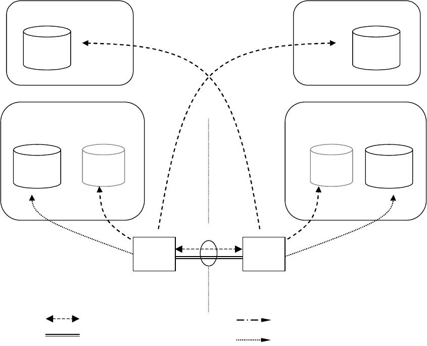
ETSI
ETSI TS 133 310 V16.5.0 (2020
-
11)
32
3GPP TS 33.310 version 16.5.0 Re
lease 16
Figure 5: Repositories for TLS case
TLS server CA
B
TLS client CA
A
Security domain A
Security domain B
TLS handshake
TLS record protocol
Interconnection CA
B
Local
CRL B
Interconnection CA
A
Local
CRL A
Public
CRL B
Public
CRL A
LDAP query
a) a)
b) b)
Local
CR A
Local
CR B
c) c)
TLS
client
TLS
server
LDAP or HTTP query

ETSI
ETSI TS 133 310 V16.5.0 (2020
-
11)
33
3GPP TS 33.310 version 16.5.0 Release 16
SEG CA
B
NE CA
A
Security domain A
Zb
NE
A
SEG
B
IKE "connection"
ESP tunnel
CRL B CRL A
CRL query
b) b)
Figure 6: Repositories for NDS/IP to support Zb interface
If the SEG CA, TLS CA or Interconnection CA are combined then the public and local repositories of the CA may be
implemented as separate databases or as a single database which is accessible via two different interfaces. Access to the
"public" CRL is public with respect to the interconnecting transport network (e.g. GRX). The public CRL should be
adequately protected (e.g by a firewall) and the owner of the public CRL may limit access to it according to his
interconnect agreements. Access to a public CRL database does not need to be secured.
NOTE 1: First it is not necessary to secure access to the CRL database as the retrieved CRL is integrity protected
and contains no confidential information. Secondly access via an unprotected interface is anyhow
necessary in case no currently valid security association is available to access the public CRL database.
SEGs shall use LDAP to access the CRL and cross-certificate repositories. TLS entities shall use LDAP or HTTP to
access the CRL repositories. TLS entities may use LDAP to access the cross-certificate repositories, if the cross
certificates are not stored locally in the TLS entity. NE's may use LDAP or HTTP to access the CRL repositories.
NOTE 2: Interfaces a) and c) for locating the data used to establish secure communications between operators
belong to the scope of NDS/AF (in addition to public b) interface) as the purpose is to guarantee the
interoperability between different SEGs, TLS entities and repository implementations. The possible
migration to the cross-certification with a Bridge CA would also require these interfaces to be specified.
7.2 Life cycle management
Certificate Management Protocol v2 (CMPv2) [4] shall be the supported protocol to provide certificate lifecycle
management capabilities for SEGs. All SEGs and SEG CAs shall support initial enrolment by the SEG to the SEG CA
via CMPv2, i.e. receiving a certificate from the SEG CA, and updating the key of the certificate via CMPv2 before the
certificate expires.
ETSI
ETSI TS 133 310 V16.5.0
(2020
-
11)
34
3GPP TS 33.310 version 16.5.0 Release 16
Certificate Management Protocol v2 (CMPv2) [4] should be the supported protocol to provide certificate lifecycle
management capabilities for TLS entities. All TLS entities and TLS CAs should support initial enrolment by the TLS
entity to the TLS CA via CMPv2, i.e. receiving a certificate from the TLS CA, and updating the key of the certificate
via CMPv2 before the certificate expires.
Certificate Management Protocol v2 (CMPv2) [4] shall be the supported protocol to provide certificate lifecycle
management capabilities for NEs. All NEs and NE CAs shall support initial enrolment by the NE to the NE CA via
CMPv2, i.e. receiving a certificate from the NE CA, and updating the key of the certificate via CMPv2 before the
certificate expires.
Enrolling a certificate to a SEG, NE or TLS entity is an operation that may be done more often than inter-operator
cross-certifications, thus more automation could be required by the operator than is possible with a PKCS#10 approach.
However, also manual SEG and NE certificate installation using PKCS#10 formats shall be supported. It should be also
noted that the lifetime of a SEG CA cross-certificate is considerably longer than the lifetime of a SEG certificate.
NOTE: CMPv2 is preferred to CMPv1 (specified in obsoleted RFC 2510), because of the interoperability issues
with CMPv1.
7.3 Cross-certification
Both operators use the following procedure to create a SEG CA or TLS CA cross-certificate:
1. The SEG CA or TLS CA creates a PKCS#10 certificate request, and sends it to the other operator;
2. The Interconnection CA receives a similar request from the other operator;
3. The Interconnection CA accepts the request and creates a new cross-certificate;
4. The SEG CA cross-certificate is stored once into the local CR of the Interconnection CA and LDAP is used to fetch
cross-certificates. The TLS CA cross-certificate may be stored once into the local CR of the Interconnection CA and
LDAP is used to fetch cross-certificates. Alternatively the TLS CA cross certificate may be locally stored in the TLS
entities.
7.4 Revoking a SEG/TLS CA cross-certificate
The following procedure is used to revoke a SEG CA cross-certificate:
1. The cross-certificate is added into the Interconnection CA's CRL;
2. The cross-certificate is removed from the Interconnection CA's CR.
The following procedure is used to revoke a TLS CA cross-certificate:
1. The cross-certificate is added into the Interconnection CA's CRL;
2. If the TLS CA cross certificates are stored in the Interconnection CA's CR, then the cross-certificate is removed.
3. If the TLS CA cross-certificates are stored locally in the TLS entities, then the locally stored cross-certificates are
deleted in the TLS entities.
7.5 Establishing secure connections between NDS/IP end
entities using IKE on the Za interface
Certificate based authentication during the IKEv2 IKE_INIT_SA/IKE_AUTH exchanges is shown in figure 4 above.
The SEGa uses the following procedure to authenticate SEGb:
1. SEGa requests SEGb's certificate using the CERTREQ payload;
2. SEGa receives SEGb's certificate inside the CERT payload;
3. SEGa authenticates SEGb (verifies signatures);
ETSI
ETSI TS 133 310 V16.5.0 (2020
-
11)
35
3GPP TS 33.310 version 16.5.0 Release 16
4. SEGa fetches a CRL from the (public) CRL database of SEG CAb if the locally cached CRL has expired;
5. SEGa uses this CRL to verify the status of SEGb's certificate;
6. SEGa uses either the locally cached cross-certificate or fetches the cross-certificate from the (local) Interconnection
CAa CR to verify SEGb's certificate;
7. SEGa fetches a CRL from the (local) Interconnection CAa CRL if the locally cached CRL has expired;
8. SEGa uses this CRL to verify the status of the SEG CA cross-certificate;
9. SEG A verifies the cross-certificate for Operator B's SEG CA using Operator A's Interconnection CA's certificate.
SEGa verifies the status of the Interconnection CAa certificate if the Interconnection CAa is not a top-level CA,
otherwise Interconnection CAa is implicitly trusted;
NOTE: If the local SEG CA public key is securely installed on every SEG within an operator's domain, then a
cross-certificate does not need to be checked when SEGa and SEGb belong to the same operator's
domain.
7.5a Establishing secure connections using TLS
The procedure for establishing secure connections using TLS is specified in detail in clause 5.2.2.
7.5b Establishing secure connections between NDS/IP entities
on the Zb interface
The procedure for establishing secure connections using NDS/IP on the Zb interface is specified in detail in clause
5.2.2.
7.6 CRL management
NDS/AF compliant SEGs and NEs shall not send an ISAKMP CERTREQ where the Certificate Type is "Certificate
Revocation List (CRL)". Receiving NEs and SEGs may ignore this request as section 6.1.3 specifies that CRLs shall be
retrieved via a CRL distribution point.
The CRL issuer (which is in most cases the CA) shall only issue full CRLs. The use of delta CRLs is not allowed
because of possible interoperability problems and because in the NDS/AF environment the full CRL is not expected to
grow too large. The full CRL shall only contain revoked certificates applicable for use within NDS/AF. The CRL issuer
shall issue a CRL also in cases that there are no revoked certificates. A SEG, NE or TLS entity is not obliged to query
for a CRL via the CRL Distribution Point if a cached one is still available and valid. If no valid cached CRL is
available, the NE, SEG or TLS entity shall fetch a new CRL. If no valid CRL can be fetched, the NE, SEG or TLS
entity shall treat this as an error and cancel tunnel establishment.

ETSI
ETSI TS 133 310 V16.5.0 (2020
-
11)
36
3GPP TS 33.310 version 16.5.0 Release 16
8 Backward compatibility for NDS/IP NE's and SEGs
NDS/IP describes an authentication framework whereby the initial IKEv2 authentication is based on the Pre-shared
Secret Key (PSK) authentication method. NDS/AF describes an optional authentication framework which enables
NDS/IP end entities (NEs and SEGs) to perform the initial IKEv2 authentication based on signatures. An NDS/AF
compliant end entity shall also contain NDS/IP functionality. However, an NDS/IP compliant end entity need not
contain NDS/AF functionality unless specifically mandated by TS 33.210[1] or any other 3GPP specification.
Device-specific management has to be used to reconfigure an end entity such that NDS/AF functionality will be used at
the IKE initiator side for the initial IKE authentication (IKEv2 IKE_INIT_SA/IKE_AUTH exchange). The transition
towards NDS/AF-based authentication may be done on an end entity by end entity basis. Before the first NDS/AF end
entity is taken into use it shall be assured that all needed NDS/AF functionality like CRs, CRL databases are available
and working. The setting up of a NDS/AF-based IPsec tunnel can be tested in parallel to the protection of existing
traffic using the PSK authentication method.
A smooth migration may be done in the following way:
- a NDS/AF end entity shall provide several algorithm proposal's during IKE initial authentication, some based on
signature authentication, others based on the PSK authentication;
- the responding IKE peer will select PSK authentication method if it does not support signature authentication
methods, but it may select a signature authentication method if it complies with NDS/AF.
- the IKE responder policy shall be configured such that the signature authentication methods shall take
precedence over the PSK authentication method to ensure that it is used as soon as the IKE initiator proposes a
signature authentication method.
In case of migration on the Za-interface between two operators:
If the SEGs of both operators support NDS/AF-based authentication then both SEG settings may be changed. The pre-
shared secrets may then be removed from the SEGs and the IKE initiator shall only use the RSA signature
authentication method. However, this removal of PSK is not essential as it may be used as a fallback mechanism. Some
care has to be taken that the policy between SEGs of different operators be coordinated otherwise this may result in
failed tunnel set up. This would be the case if the initiating IKE peer only uses the RSA signature authentication method
and the responding IKE peer only accepts the PSK authentication method. Furthermore, if the PSK is kept as a fallback
mechanism after the RSA signature authentication method is introduced, then fallback to PSK should only be allowed if
the operator makes a policy change in the SEGs to allow PSK to be used. The operator may temporarily allow fallback
to PSK if, for example, the SEGs are unable to verify the necessary certificates because of problems with the PKI. If
PSK is kept as a fallback then it may be necessary to renew the PSK periodically for security reasons, or if PSK
compromise is suspected.
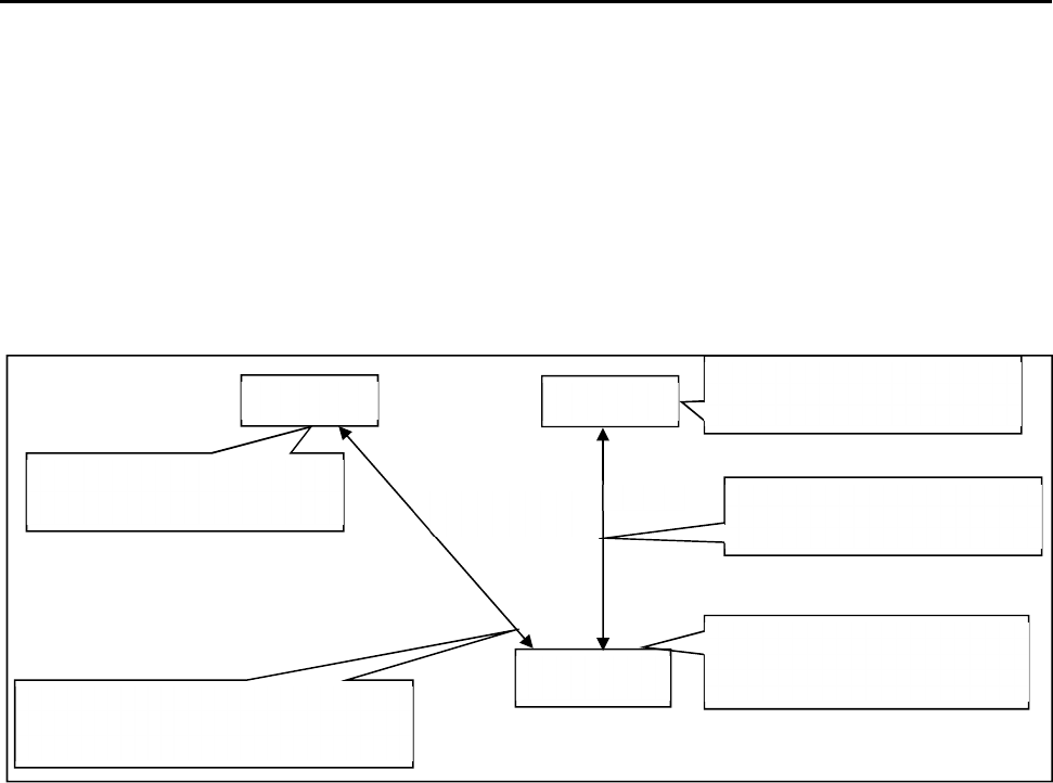
ETSI
ETSI TS 133 310 V16.5.0 (2020
-
11)
37
3GPP TS 33.310 version 16.5.0 Release 16
9 Certificate enrolment for base stations
9.1 General
The clause specifies certificate enrolment mechanisms for backhaul security. The decision on whether or not to apply
the mechanisms is left to other 3GPP specifications.
9.2 Architecture
Figure 7 shows the general deployment architecture for certificate enrolment of a base station at an operator PKI.
Figure 7: Overview of the security architecture
The base station is pre-provisioned with a public-private key pair by the vendor, and has the vendor-signed certificate of
its public key pre-installed.
As RA/CA, an operator may deploy:
- either a stand-alone CA implementing a CMPv2 server,
- or, a CA having delegated certain tasks to an RA, which is in this case operating the CMPv2 server.
On initial contact to the operator network the base station establishes a communication channel to the RA/CA of the
operator. Using CMPv2 [4] a request for a certificate is sent to the RA/CA. The network authenticates the messages
from the base station based on the vendor-signed certificate of the base station and the vendor root certificate pre-
installed in the network. The base station shall check the integrity protection on the messages from the RA/CA based on
the operator root certificate provisioned in the base station. In a response message the base station receives the operator-
signed certificate. During the execution of the CMPv2 protocol the base station has to successfully provide a Proof of
Possession of the private key associated to the public key to be certified.
The operator root certificate may be provisioned in the base station prior to or during the CMPv2 protocol run. The
protection of the operator root certificate during provisioning may be decided by operator security policy. If an operator
root certificate provisioned prior to the CMPv2 protocol run is available the base station shall use it. Otherwise, the base
station shall use the operator root certificate provisioned during the CMPv2 run. If no operator root certificate is
provisioned at all then the base station shall abort the procedure.
After enrolment has been performed, the base station can use the operator-signed certificate to authenticate itself to the
SEG of the operator, which is pre-installed with the operator root certificate. The base station then authenticates the
SEG using the operator root certificate.
NOTE: The authentication towards the SEG is part of the normal usage of IPsec-based backhaul security
according to TS 33.210 [1].
RA/CA
base station
The base station obtains the operator-
signed certificate on its own public key
from RA/CA using CMPv2.
CMPv2
Vendor-signed certificate of base
station public key is pre-installed.
Vendor root certificate is pre-
installed.
SEG
Operator root certificate is pre-
installed.
Enrolled base station certificate
is used in IKE/IPsec.
IPsec
ETSI
ETSI TS 133 310 V16.5.0 (2020
-
11)
38
3GPP TS 33.310 version 16.5.0 Release 16
If at later stage of base station deployment the operator wants to renew the base station certificate, the same procedure
will be executed with the old operator-signed certificate of the base station taking the place of the vendor-signed
certificate in the initial enrolment.
9.3 Security Mechanisms
The enrolment of base stations shall use the CMPv2 protocol as specified in RFC 4210 [4] and RFC 4211 [19]. The
proof-of-possession methods as given by [4] and [19] shall be used.
The profiling of CMPv2 for the purpose of base station enrolment is given in subclause 9.5 of the present document.
9.4 Certificate Profiles
9.4.1 General
All certificates used during the enrolment process of base stations shall follow the requirements given in clause 6 of the
present document. Profiling and exceptions are specified in the following subclauses.
9.4.2 Vendor Root CA Certificate
The root certificate of the vendor root CA shall follow the requirements given in subclause 6.1.2 for interconnection CA
certificate profiles, with the following exceptions:
- the vendor shall support distribution of certificate revocation information. The interface to provide revocation
data is out of scope of the present document.
9.4.3 Vendor CA Certificate
If the vendor does not sign the base station certificate by its vendor root CA, the certificate of the CA signing the base
station certificates and of any intermediate vendor CA shall follow the requirements given in subclause 6.1.4 for SEG
CA certificate profiles, with the following exceptions:
- the issuer name shall be the name of any vendor CA, given that the resulting chain of certificates starting with
the base station certificates leads to the vendor root CA;
- the path length shall be greater than 0 for the certificate of an intermediate CA not directly signing the vendor
base station certificates;
- the CRL distribution point extension in the certificate shall be optional;
- the provisions on distribution of certificate revocation information given in subclause 9.4.2 shall apply.
9.4.4 Vendor Base Station Certificate
The base station certificate signed by a vendor CA shall follow the requirements given in subclause 6.1.3b for NE
certificate profiles, with the following exceptions:
- the issuer name is the name of the vendor CA signing the base station certificate;
- the subject name shall be a globally unique fully qualified domain name (FQDN) given by the vendor. The exact
definition of this FQDN is left to the vendor, given that the vendor ensures global uniqueness. The format of the
subject name shall follow subclause 6.1.1 using the variant with an o attribute and a cn attribute, where the o
attribute shall contain the vendor name, and the cn attribute shall contain the FQDN.
- the subjectAltName with type dNSName shall contain the same FQDN as the subject field;
NOTE 1: Availability of DNS is not required for the FQDN in the certificate.
ETSI
ETSI TS 133 310 V16.5.0 (2020
-
11)
39
3GPP T
S 33.310 version 16.5.0 Release 16
NOTE 2: An example for the vendor base station FQDN is <serialnumber>.<vendor>.com. Note that all labels
must comply with the requirements for labels in FQDNs (cf. RFC 1035 [25]). The representation in the
subject field would be "o=<vendor name>, cn=<serialnumber>.<vendor>.com".
- the provisions on the CRL distribution point extension in the certificate and on distribution of certificate
revocation information given in subclause 9.4.3 shall apply.
9.4.5 Operator Root CA Certificate
The root certificate of the operator root CA shall follow the requirements given in subclause 6.1.2 for interconnection
CA certificate profiles.
9.4.6 Operator RA/CA Certificate
If operating a standalone CA, the operator may deploy separate private keys for signing certificates and for signing the
CMP messages or he may use one single private key for both purposes. In consequence the CA may have two or one
certificate(s) being actively utilized in this transaction.
The operator may utilize a CA for signing certificates and delegate operation of the CMPv2 server to an RA. If RA and
CA are different entities, the private keys as well as the subject names of the certificates used by the CA for signing
base station certificates and by the RA for signing CMP messages are different.
The CA certificate used for signing certificates shall follow the requirements given in subclause 6.1.4 for SEG CA
certificate profiles, with the following exception:
- the issuer name shall be the name of any operator CA, given that the resulting chain of certificates starting with
the CA certificate leads to the operator root CA.
The RA/CA certificate used for signing CMP messages shall follow the requirements given in subclause 6.1.3 for SEG
certificate profiles, with the following exceptions:
- the subject name shall be the same name as used in the "sender" field of the CMPv2 messages;
- the issuer name shall be the name of any operator CA, given that the resulting chain of certificates starting with
the RA/CA certificate leads to the operator root CA.
If the operator deploys one single private key for signing of the base station certificates and for signing of the CMP
messages, for the single RA/CA certificate the same requirements as above for the CA certificate used for signing
certificates apply with the following addition:
- in addition to the key usage extensions specified in subclause 6.1.4, mandatory critical key usage extension bit
digitalSignature shall be set.
NOTE: According to common security practices, the usage of separate private keys and certificates for signing of
the base station certificates and for signing of the CMP messages is recommended.
9.4.7 Intermediate Operator CA Certificate
If the operator does not sign the RA/CA certificate by its operator root CA and if the RA/CA certificate(s) are not
directly signed by the operator root CA, the certificate of any intermediate operator CA shall follow the requirements
given in subclause 6.1.4 for SEG CA certificate profiles, with the following exceptions:
- the issuer name shall be the name of any operator CA, given that the resulting chain of certificates starting with
the RA/CA certificates leads to the operator root CA;
- the path length shall be greater than 0.
9.4.8 Operator Base Station Certificate
The base station certificate signed by the operator RA/CA shall follow the requirements given in subclause 6.1.3b for
NE certificate profiles.
Other documents may specify different base station certificate profiles according to their deployment scenario.
ETSI
ETSI TS 133 310 V16.5.0 (2020
-
11)
40
3GPP TS 33.310 version 16.5.0 Release 16
NOTE: The intended usage of the base station certificate may have requirements different from the usage of NE
certificates as specified in the present document on NDS/AF. Thus the exact profile may depend on other
documents specifying the intended deployment scenario.
9.5 CMPv2 Profiling
9.5.1 General Requirements
The following requirements shall apply to CMPv2 usage end-to-end between base station and RA/CA:
- This CMPv2 profile shall only include certificate request and key update functions. Revocation processing,
PKCS#10 requests and CRL fetches shall not be part of this CMPv2 profile.
- For PKI Message Protection, this CMP profile shall only use an asymmetric algorithm. PasswordBasedMac is
not used in the scope of the present document.
- The base station shall be pre-provisioned with a private/public key pair (vendor key pair) and with the related
vendor base station certificate signed by a vendor CA.
- If there is a certificate chain from the base station certificate up to the vendor root CA, also the intermediate
certificates shall be pre-provisioned to the base station.
- The base station may be pre-provisioned with the operator root CA certificate.
- If the base station is not pre-provisioned with the operator root CA certificate, then the base station shall take the
operator root certificate from the certificates received in the initialization response. The selection shall be based
on checking which root certificate can be used to validate the received base station certificate.
NOTE 1: Certificate renewal for operator root certificates is not in scope of this clause on base station enrolment.
Thus it is assumed that the base station always has a valid operator root certificate available for validation
of key update responses.
- The RA/CA shall authenticate initialization requests based on signatures which are validated against the vendor
root CA.
- The RA/CA shall authenticate key update requests based on signatures which are validated against the operator
root CA.
- The RA/CA shall be configured with the root certificate of the vendor and with the root certificate of the
operator.
- The RA/CA shall be configured with a RA/CA certificate which is signed either by the operator root CA or by
an intermediate CA under the operator root CA.
- If the RA/CA uses different private keys to sign the generated certificates and the CMPv2 messages, the RA/CA
shall be configured with the two related certificates, i.e. the RA/CA certificate for signing signatures and the
RA/CA certificate for signing CMP messages.
- If the RA/CA certificate or certificates (two in case separate private keys are used for signing of certificates and
CMP messages) are not signed directly by the operator root CA, also the certificates of the intermediate CAs
shall be configured into the RA/CA.
- The hash algorithms used before generating signatures in the protection field of PKIMessage and for proof-of-
possession shall be the same as the hash algorithms specified in subclause 6.1.1 for certificate signatures. The
signature algorithms shall be the same as that used in the related certificate profile.
The certificate profiles are specified in subclause 9.4.
NOTE 2: These certificate profiles implicitly specify which algorithms are to be used for the different signatures for
proof-of-possession and PKIMessage signing specified in the following subclauses.
NOTE 3: Policies within RA/CA governing the generation and issuing of certificates are not in scope of the present
document and left to operator decision.
ETSI
ETSI TS 133 310 V16.5.0 (2020
-
11)
41
3GPP TS 33.310 version 16.5.0 Release 16
9.5.2 Profile for the PKIMessage
The following profile shall be applied to the PKIMessage as specified in [4]:
- The support and usage of the optional protection field of type PKIProtection is required by this profile. The
message-specific private key to be used in the base station is specified in the subclause 9.5.4 in the profiling of
the single PKI message bodies for requests sent by the base station. For the RA/CA the RA/CA private key shall
be used, or the separate RA/CA private key for signing CMP messages, if base station certificates and CMPv2
messages are signed by different private keys.
- The support of the optional extraCerts field is required by this profile. The certificates within this field may be
ordered in any order. The message-specific content of this field is specified in the subclause 9.5.4 in the profiling
of the single PKI message bodies.
- All CMPv2 messages used within this profile shall consist of exactly one PKIMessage, i.e. the size of the
sequence for PKIMessages shall be 1 in all cases.
9.5.3 Profile for the PKIHeader Field
The following profile shall be applied to the PKIHeader field as specified in [4]:
- The sender and recipient fields shall contain the identities of the base station and the RA/CA. These identities
shall be identical to the subject name present in the certificate for the public key whose related private key is
used to sign the PKIMessage.
NOTE: The subject name of RA/CA needs to be available before the CMPv2 run. The base station can obtain this
subject name of RA/CA before the CMPv2 run via e.g., Initial IP Autoconfiguration procedure specified
in TS 32.508[32] and TS 32.509[33].
- As the field “protection” of PKIMessage is mandatory, also the field “protectionAlg” of PKIHeader is
mandatory. The protectionAlg shall be of type MSG_SIG_ALG. The signature algorithm shall be based upon the
algorithm contained in the algorithm field of the SubjectPublicKeyInfo field of the signer’s certificate (belonging
to the base station or the RA/CA). The hash algorithm used before signing the PKIMessage shall follow the same
specification as given for usage before certificate signing in clause 6.1.1 of the present document.
- The usage of the transactionID field is mandatory. The recommended procedures for handling of the
transactionID given in [4] shall be followed. The base station shall set this field to a random number that is at
least 8 bytes long for the first message and use the same random number in any subsequent message in the
transaction.
- The usage of the senderNonce and the recipNonce fields is mandatory. The length of the fields as recommended
in [4] shall be used. The recipNonce in the very first message in the transaction should be set to 0 by the sender
and shall be disregarded by the recipient of the message.
9.5.4 Profile for the PKIBody Field
9.5.4.1 General
The base station certificate enrolment shall support the following CMPv2 PKI message bodies:
- Initialization Request (ir)
- Initialization Response (ip)
- Key Update Request (kur)
- Key Update Response (kup)
- Confirmation (pkiconf)
- Certificate confirm (certconf)
ETSI
ETSI TS 133 310 V16.5.0 (2020
-
11)
42
3GPP TS 33.310 version 16.5.0 Release 16
Profiles for the single message bodies above are given in the subclauses below. If no specific profile is given, the
provisions of [4] and [19] apply.
9.5.4.2 Initialization Request
The Initialization Request as specified in IETF RFC 4210 [4] shall contain exactly one CertReqMessages as specified in
IETF RFC 4210 [4] and IETF RFC 4211 [19], i.e. the size of the sequence for CertReqMessages shall be 1 in all cases.
The following profile shall be applied to the CertReqMessage field and its sub-fields:
- The subject field of the CertTemplate shall contain the suggested name of the base station if the base station has
knowledge of it. Otherwise it shall be omitted.
- The publicKey field of the CertTemplate shall be mandatory and shall contain the public key of the base station
to be certified by the RA/CA. The private/public key pair may be pre-provisioned to the base station, or
generated inside the base station for the CMPv2 protocol run. The format of this field shall follow IETF RFC
5280 [14].
NOTE 1: IETF RFC 3280 as referenced by IETF RFC 4211 [19] for the format of the publicKey field is obsolete.
The present document generally references the follow-up IETF RFC 5280 [14].
- The CertReqMessage shall contain a POP field of type ProofOfPossession. The POP field shall contain a
signature field of type POPOSigningKey. The algorithmIdentifier field of the POPOSigningKey field shall
contain the signing algorithm which is used by the base station to produce the Proof-of-Possession value, i.e. the
signature within POPOSigningKey field.
- If the poposkInput field of type POPOSigningKeyInput within POPOSigningKey field is used, the sender field
within POPOSigningKeyInput shall be mandatory and shall contain the identity of the base station as given by
the vendor of the base station and contained in the vendor-provided base station certificate.
NOTE 2: According to IETF RFC 4211 [19], the poposkInput field is mandatory if either the subject field or the
publicKey field of the CertTemplate field is omitted.
NOTE 3: According to IETF RFC 4211 [19], the sender field of POPOSigningKeyInput is used only if an
authenticated identity has been established by the sender. The present document assumes that the sender
(i.e. base station) has a valid pre-provisioned vendor-signed certificate and therefore the sender’s identity
is considered authenticated and established.
The PKIMessage sent by the base station shall be signed by the vendor provided private key.
The extraCerts field of the PKIMessage carrying the initialization request shall be mandatory and shall contain the base
station certificate provided by the vendor. If the base station certificate is not signed by the vendor root CA, also the
intermediate certificates for the chain up to the vendor root certificate shall be included in the extraCerts field.
9.5.4.3 Initialization Response
The Initialization Response as specified in [4] shall contain exactly one generated base station certificate, i.e. the size of
the sequence for CertResponse shall be 1 in all cases.
The following profile shall be applied to the CertRepMessage field and its sub-fields:
- The generated certificate shall be transferred to the base station in the certifiedKeyPair field of the CertResponse
field. The transfer shall not be encrypted (i.e. the certificate field in CertorEncCert shall be mandatory).
The extraCerts field of the PKIMessage carrying the initialization response shall be mandatory and shall contain the
operator root certificate and the RA/CA certificate (or certificates if separate private keys are used for signing of
certificates and CMP messages). If the RA/CA certificate(s) are not signed by the operator root CA, also the
intermediate certificates for the chain(s) up to the operator root certificate shall be included in the extraCerts field.
9.5.4.4 Key Update Request and Key Update Response
The structure and content of these messages is identical to initialization requests and responses, thus the profiling given
in the previous subclauses for Initialization Request and Initialization Response apply equally, with the following
exceptions:
ETSI
ETSI TS 133 310 V16.5.0 (2020
-
11)
43
3GPP TS 33.310 version 16.5.0 Release 16
- The PKIMessage sent by the base station shall be signed with the private key which is related to the last received
operator provided base station certificate. The extraCertsField shall be mandatory and shall contain the base
station certificate related to the private key used for signing the PKIMessage. Any intermediate CA certificates
shall also be included, if the base station certificate is not signed directly by a root CA.
- The PKIMessage carrying the key update response should not contain the operator root certificate in the
extraCerts field.
9.5.4.5 Certificate Confirm Request and Confirmation Response
Initialization responses and key update responses shall always be followed by a Certificate Confirm request and
Confirmation response message exchange.
The PKIMessage sent by the base station shall be signed by the same private key which was used in the preceding
initialization request or key update request.
The extraCerts field of the PKIMessage carrying the Certificate Confirm request and Confirmation response shall be
omitted.
9.6 CMPv2 Transport
Transport of CMPv2 messages between end entities (network elements) and RA/CA shall be done using HTTP-based
protocol as specified in IETF RFC 6712 [18] , with the exception that support for TLS is not mandated.
Support is mandatory for communication initiated by the end entities where every CMP request triggers a CMP
response message from the CA or RA. Support for RA/CA initiated HTTP requests (i.e. announcements) is not
mandatory.
NOTE: CMP provides built-in integrity protection and authentication. For optional usage of HTTP over TLS
(HTTPS) according to RFC 2818 [20] or virtual private networks see IETF RFC 6712 [18].

ETSI
ETSI TS 133 310 V16.5.0 (2020
-
11)
44
3GPP TS 33.310 version 1
6.5.0 Release 16
Annex A (informative):
Void

ETSI
ETSI TS 133 310 V16.5.0 (2020
-
11)
45
3GPP TS 33.310 version 16.5.0 Release 16
Annex B (informative):
Decision for the simple trust model
B.1 Introduction
In order to document the decision for the "simple trust model", which requires manual cross-certification, this section
discusses technical advantages and disadvantages of two basic approaches to providing inter-operator trust for purposes
of roaming traffic protection, namely cross-certification and a Bridge CA. The Bridge CA is an extension of the cross-
certification approach, and identified as one of the recommendable solutions for providing inter-operator trust in
NDS/AF feasibility study (TR 33.810). Taking into account the current state of PKI software and the general need for
simple solutions when there is a choice, the cross-certification without a Bridge CA was chosen for the NDS/AF TS.
This Annex discusses the background motivation for such direction.
The direct cross-certification without Bridge CA model is associated strongly with the current practice in the Internet
IPsec world, where each IPsec connection is configured with a list of trusted CAs, and anyone with a certificate that has
a trust path that can be followed up to such trusted CA (trust anchor) is allowed access. In this model, cross-certification
is done at the time the roaming agreement is made. This is called the "simple trust model."
The Bridge CA model assumes that all operators wishing to establish a roaming agreement with other operators will
first get certified by the Bridge CA for purposes of identification by other operators. This is a necessary preliminary
step. Next, when the roaming agreement is done, the operators will configure their IPsec tunnels, with information
about which one of the identifiable operators (who have a certificate issued by the Bridge CA) can use that tunnel. This
is called the "extended trust model", or "separated trust and access control."
This Annex does not discuss the benefits of certificates vs. Pre-Shared Keys. The benefit of cross-certification vs. the
explicit listing of roaming peer CAs includes the easier evolution path to a possible eventual Bridge CA model.
B.2 Requirements for trust model in NDS/AF
The following is a list of requirements for the trust model for NDS/AF:
A. Simplicity and ease of deployment. PKI brings many benefits when a large number of operators need to tunnel
traffic in a mesh configuration, but its adoption should not be hindered by an unnecessarily complex technical solution.
The required technical and legal operations necessary for exchanging traffic with another operator should be as easy and
straightforward as possible;
B. Compatibility with existing standards. Unless there are explicit requirements why existing PKI standards should be
extended to accommodate 3GPP environment, the 3GPP specifications should be accommodated to the existing
standards. This allows best choice of equipment for operators and allows interoperability with non-3GPP environments;
C. Usable by both GRX and non-GRX operators. Both operators making use of GRX providers and those without
(using leased lines or even the public Internet), should be able to make use of NDS/AF measures to exchange traffic
securely.
B.3 Cross-certification approaches
B.3.1 Manual Cross-certification
The trust model of manual cross-certification is characterized by the clause: "Trust nobody unless explicitly allowed".
Issuing a certificate for the authority to be trusted creates the allowances. The manual cross-certification is easy to
understand. Also the security of this depends only on the decisions done locally.

ETSI
ETSI TS 133 310
V16.5.0 (2020
-
11)
46
3GPP TS 33.310 version 16.5.0 Release 16
B.3.2 Cross-certification with a Bridge CA
The trust model of bridge-CA can be characterized by the clauses:
- "Trust everybody that the Bridge-CA trusts unless explicitly denied". Explicit denials are handled by writing the
restrictions (in the form of name constraints) to the certificate issued to the bridge.
- "Trust everybody listed in the certificate which I issued to the bridge". Explicit allowances are listed in the
certificate issued to the bridge (in the form of name constraints).
Name constraint is a rarely used extension for X.509 certificates. In essence it is a clause that says who to trust or who
not to trust based on names on certificates. The fact that they are relative rarely used and the fact that there is so little
official documentation about them is a risk. Name constraints also require that there is some organization doing
registration of names in order to avoid name collisions.
B.4 Issues with the Bridge CA approach
B.4.1 Need for nameConstraint support in certificates or strong
legal bindings and auditing
If no precautions are taken, it is possible that an operator (M) whose SEG CA has been signed by the Bridge CA
(= certified by the Bridge), creates certificates that resemble another operator's (A) certificates, letting M access to
operator (B)'s network, even without authorization.
Let's say operator B has the following configuration for access to her subnetwork reserved for handling roaming traffic:
- Local-Subnetwork = some ipv6 subnetwork address;
- TrustedCA's = BridgeCA;
- AllowedCertificateSubject = O=Operator A or O=Operator C or O=Operator D.
NOTE: The IP addresses of the remote SEGs are not limited, as authentication is done based on certificates, and
all trusted operators are allowed similar access. If different foreign operators would require to access
different subnetworks, there would be several configuration blocks like the above, with the IP addresses
appropriately specified.
Such "AllowedCertificateSubject" feature (the term name is imaginary) is widely supported by PKI-capable IPSec
devices.
If Operator M used certificates of the following form for her certificates, she would not be allowed in:
- Subject: CN=SEG 1, O=Operator M;
- Signer: CN=SEG CA, O=Operator M.
However, she can fabricate certificates of the following form:
- Subject: CN=SEG 1, O=Operator A;
- Signer: CN=SEG CA, O=Operator M.
Using such certificates would allow full but illegitimate access to Operator B's network revealed for use by Operator A.
Now, there are the following possibilities to circumvent the problem:
1. checking also the Signer name when authenticating foreign operators, either by a) a proprietary
"AllowedCertificateSigner" property or b) support for nameConstraints in the Bridge CA certificate issued to operator
M;
2. establishing strong legal bindings and auditing that would discourage Operator M from such illegitimate fabrication
of Operator A certificates.
ETSI
ETSI TS 133 310 V16.5.0 (2020
-
11)
47
3GPP TS 33.310 version 16.5.0 Release 16
The problem with solution 1.a is that such "AllowedCertificateSigner" is not commonly supported by current PKI end-
entity products, being in conflict with requirement B.
The problem with solution 1.b is that such "nameConstraints" attribute in certificates is not commonly supported by
current PKI CA or end-entity products, being in conflict with requirement B.
The problem with solution 2 is that first of all, an organization willing to run a Bridge CA has to be found before any
pair of operators can exchange roaming traffic with NDS/AF mechanisms. Next, there shall be established paperwork
and auditing procedures to make sure that the exploit described here can be detected. This is in conflict with
requirement A. Also, the illegitimate act described could not be technically prevented beforehand.
If name constraints are used, every time a new roaming agreement is made, each operator shall update the certificate
they issue for the Bridge, adding the new roaming partner's name into the certificate. From the point of view of one
operator, the number of new certificate signing operations is the same whether a Bridge CA or a direct cross-
certification model is in use.
B.4.2 Preventing name collisions
If name constraints are used to prevent the additional "bureaucracy" involved with the Bridge CA, the names written
into the certificate need to be registered with a third party to prevent two operators accidentally or on purpose using the
same name in their certificates. This is in conflict with requirement B.
B.4.3 Two redundant steps required for establishing trust
As described in the introduction, with the "extended trust model", each operator shall first be certified by the bridge
(authentication), and then as the second step, enumerate the trusted operators when configuring the IPSec tunnel (access
control).
For the Bridge CA model to work, there is a need for organization that all the other parties involved can trust - and the
trust shall be transitive! If you trust the bridge, you shall also trust the other organizations joining to the bridge via the
cross-certification. If Operator A and the Bridge CA cross-certify with each other, Operator A will automatically trust
every other certified operator to obey the rules. And this trust is not related to the roaming traffic tunnel; the tunnel has
to be configured independently of the PKI.
So even if configuring new certificates in the SEGs is avoided when cross-certification is used, the roaming information
shall be configured and maintained in the SEG some other way. And the hard part: How the trust provided by the PKI
and the roaming agreements is combined, because clearly in this case PKI provided trust is not the same as roaming
agreements.
Two steps would be needed:
1. building "trust" through Bridge CA => authenticating the peer SEG;
2. specify in the tunnel configuration which peering SEGs can be trusted.
If the cross-certification is done without a Bridge CA, the steps can be combined into one. What is the additional value
of the PKI provided trust (step 1), if the peering SEGs have to be restricted in any case?
B.4.4 Long certificate chains connected with IKE implementation
issues
If Bridge CA is used, a SEG CA certificate has to be sent in the certificate payload in addition to the local end entity
(SEG) certificate. This leads in Ethernet environments to the fragmentation of the IKE packet, which some current IKE
implementations do not support. It is a problem in the implementation, not the protocol. Even in IPv6, the IKE UDP
packets need to be fragmented, posing a potential interoperability problem. Clearly it is not a solution to use a different
protocol, but instead the current implementations should be fixed. Still, taking into account requirement B, it is safer to
avoid the problem altogether by not forcing the fragmentation of IKE packets by not using a Bridge CA.

ETSI
ETSI TS 133 310 V16.5.0 (2020
-
11)
48
3GPP TS 33.310 version 16.5.0 Release 16
B.4.5 Lack of existing relevant Bridge CA experiences
The Federal PKI in the USA is an example deployment where a Bridge CA is used to connect together CAs of the
various federal agencies. It seems to be however the only documented one of its kind, and is connected with very heavy
policy documentation and obviously heavy auditing practices, even within one organization, the federal government.
The bridge approach is warranted in the case, because they want to automatically check whether some entity has legal
rights to sign some document. The number of entities doing cross-domain PKI validation can be several millions, and it
is impossible for one validating entity to keep count of individual signers.
In 3G roaming, the situation is in many ways different. When a new operator is born, the other ones do not
automatically want to exchange roaming traffic with the new one, but a legal agreement with that operator and a
technical tunnel establishment shall be done. In Federal PKI, the situation is the opposite: nothing should need to be
done and still be able to trust the other.
In the Federal PKI, the paperwork and processes make name constraints in certificates unnecessary, and IKE is
supposedly not used together with the Bridge CA.
B.5 Feasibility of the direct cross-certification approach
This chapter discusses the direct cross-certification, i.e. manual cross-certification approach, where operators are doing
the cross-certification operation only when agreeing to set up a tunnel with another operator. This tunnel setup is a legal
and technical operation in any case, so it is feasible to do also the cross-certification at this time, removing the need for
the initial step to cross-certify with the Bridge CA.
There is no technical difference regarding the feasibility of direct cross-certification or Bridge CA in the context of
GRX or non-GRX environment. GRX might be one possible choice for providing the Bridge CA services.
B.5.1 Benefits of direct cross-certification
The benefits of the direct cross-certification is that as a mechanism it is well known, supported widely by current PKI
products and there even exists an evolution path to a Bridge CA solution if the products come to support it adequately, a
Bridge CA is established, and the number of operators becomes so large to warrant the use of the Bridge CA
technology. Bridge CA uses the cross-certification mechanisms in any case.
The tunnel configuration would look like the following:
- Local-Subnetwork = some ipv6 subnetwork address;
- TrustedCA's = LocalCA.
The information of which operator is allowed access is implicit in the direct cross-certifications that have been done by
the LocalCA, thus authentication and access control are tightly connected. If different foreign operators need to access
different subnetworks, there would be separate tunnel configurations with SEG IP address for each, including an
"AllowedCertificateSubject" limitation. The "AllowedCertificateSigner" limitation is not needed as necessary in this
model (compared to the bridge CA model), since the set of operators which can be authenticated are only the ones, that
have previously been agreed to trust when doing the direct cross-certification. In the bridge CA case, the set of
operators which can be authenticated includes all operators who have joined to the bridge.
ETSI
ETSI TS 133 310 V16.5.0 (2020
-
11)
49
3GPP TS 33.310 version 16.5.0 Release 16
B.5.2 Memory and processing power requirements
In case of direct cross-certification, each operator shall store the certificates issued for the other operators locally. They
could be stored in the SEG devices, or then in a common repository.
If an operator makes roaming agreements with 500 other operators, this would require roughly 1000 kilobytes of
memory, if the operator signs the certificates herself, and one certificate takes 1 kilobyte of memory. This should be
quite feasible taken into account the high-end nature of SEG hardware.
Processing power benchmark for validating certificates:
- Hardware: 800 MHz Pentium III, 256 MB of memory.
- 200 x 1024-bit RSA certificates, 1 Root CA (operator's own CA), 200 Sub CAs (other operator CAs) and 200 end
entity (SEG) certificates. Also CRLs were verified. Both certificates and CRLs were loaded from disk during the test.
The whole test took 3.5 seconds, with probably disk I/O taking most of the time.
In this test 200 certificate chains were validated up to the trusted root.
B.5.3 Shortcomings
As discussed in the previous section, the Bridge CA approach saves memory or storage space in SEGs, because all the
other operators SEG CA certificates do not need to be stored with other operators. Just the Bridge CA certificate would
be stored, and other certificates retrieved during IKE negotiation.
B.5.4 Possible evolution path to a Bridge CA
If needed, it is possible to take the Bridge CA into use gradually, given that the support by PKI products becomes
reality. From one operator's point of view, the bridge CA would be like any other operator so far, and a cross-
certification would be made, but additionally the name constraints in the certificate issued for the Bridge CA should be
updated every time a new roaming agreement is made.

ETSI
ETSI TS 133 310 V16.5.0 (2020
-
11)
50
3GPP TS 33.310 version 16.5.0 Release 16
Annex C (informative):
Decision for the CRL repository access protocol for SEGs
In order to document the decision for the protocol for SEGs to access CRL repositories, this section summarises
technical advantages and disadvantages of the two candidates.
LDAP
+ implemented by all PKI products (unless purely manual)
+ scalability
+ flexibility (integration possibility to other systems, automatic public key retrieval possibility)
- complexity
HTTP
+ simple
- not supported by all PKI products (although widely supported)
LDAP was chosen as the more future-proof protocol. Although more complex than HTTP, LDAP is well established
amongst PKI vendors and operators.

ETSI
ETSI TS 133 310 V16.5.0 (2020
-
11)
51
3GPP TS 33.310 version 16.5.0 Release 16
Annex D (informative):
Decision for storing the cross-certificates in CR
In order to document the decision for storing the cross-certificates in Certificate Repository, fetching those with LDAP
and caching them in SEGs, this section summarises technical advantages and disadvantages of the three alternatives.
The following table summarizes differences between alternatives:
Table D.1
I
ssue
A) Cross
-
certificates are
stored into SEGs:
B) Cross
-
certificates are
stored into CRs:
C) Cross
-
certificates are
stored into CRs and
cached in SEGs upon
usage:
1) Initialization
issues: storing
the cross-
certificate
during the
cross-
certification
The cross-certificate is
initially stored in several
places, that is, into all
SEGs (estimated number
is between 2 and 10).
Pros: -
Cons: Certificate must be
initially copied in several
places. SEGs from
different manufacturers
may have other O&M
interfaces to handle the
certificates.
The cross-certificate is
initially stored in CR.
Pros: The handling is fully
standardized. Certificate is
initially copied in one place
only. The operator should
have the repository
anyway (due to CRL
handling).
Cons: -
The cross-certificate is
initially stored in CR.
Pros and cons as in B).
2) Usage issues:
latency during
the IKE Phase 1
Pros: No extra latency
Cons: -
Pros: -
Cons: More latency
caused by extra LDAP
query (the cross-certificate
is queried)
Pros & cons: as in B) at
the first time, and as in A)
at subsequent times
3) Cleanup issues:
removing the
cross-certificate
Pros: -
Cons: The cross-certificate
has to be removed from
several places, that is,
from all SEGs
Pros: The cross-certificate
has to be removed from
one single place only
Cons: -
Pros: -
Cons: The cross-certificate
has to be removed from
both CR and each SEG.
NOTE: this functionality is needed only to be able to revoke cross-certificates before the next CRL gets
published.
4) Security issues Pros: No single point of
failure exists.
Cons: -
Pros: -
Cons: CR represents a
single point of failure
suitable for an attacker,
e.g. to submit a denial of
service attack by breaking
the communication at the
CR.
Pros: Single point of
failure partly mitigated
Cons: -
Analysis:
- Alternative B) requires one additional LDAP query in every IKE Phase 1 negotiation and will introduce new error
cases
- Latency of LDAP: information from LDAP to local disk is cached and populating it takes some time, but in practice
this time is not significant.
- The benefit of alternative B) and C) compared to alternative A) is easier management, that is, storing and removing
the certificate in/from one single place only.
Conclusion: alternative C) is the most feasible choice, because it combines good points of alternatives A) and B).

ETSI
ETSI TS 133 310 V16.5.0 (2020
-
11)
52
3GPP TS 33.310 version 16.5.0 Release 16
Annex E (informative):
TLS protocol profile
The TLS protocol profiles are located in TS 33.210 [1].

ETSI
ETSI TS 133 310 V16.5.0 (2020
-
11)
53
3GPP TS 33.310 version 16.5.0 Release 16
Annex F (informative):
Manual handling of TLS certificates
F.0 General
The purpose of this annex is to provide alternative guidelines for TLS certificate handling in case of the absence of the
authentication framework for TLS certificates.
Within this Annex following abbreviations are used: CA
A
is the certification authority in A's network and CA
B
is the
certification authority in B's network. Cert
A
is the certificate of A and Cert
B
is the certificate of B. I
A
is the set of
identifiers that A may use for identification towards B. T
B
is the set of peers trusted by B.
F.1 TLS certificate enrolment
Mutual authentication in TLS is achieved based on public key technology and certificates. Both TLS peers A and B
need to contain a certificate store and there shall be at least one certification authority CA that can issue certificates
within the security domains in with A and B are part of. Cert
A
contains the set I
A
of A's identifiers. Each identifier is in
the form of fully qualified domain name (FQDN). Similarly, B's certificate is Cert
B
.
The certificates in the store of B define the group T
B
of peers trusted by B. There are several options for creation and
enrolment of certificates, three of which are described below.
1. In one option there is a certification authority, CA
B
, only in the network of B. CA
B
issues a certificate Cert
B
to B and
a certificate Cert
A
to A. The certificates are delivered from CA
B
to A and B in a secure way "out of band". Both A and
B then add their peer into the group of their trusted peers by inserting that peer's certificate into the certificate store: A
inserts Cert
B
into A's certificate store and B inserts Cert
A
into B's certificate store. This insertion is typically manual and
the details depend on the implementation of the management interface to the certificate store.
2. In another option both A's and B's networks contain certification authorities, CA
B
and CA
A
, respectively. CA
B
issues
a certificate Cert
B
to B and CA
A
issues a certificate Cert
A
to A. The certificates are delivered from CA
B
to A and from
CA
A
to B in a secure way "out of band". Both A and B then add their peer into the group of their trusted peers by
inserting that peer’s certificate into the certificate store: A inserts Cert
B
into A's certificate store and B inserts Cert
A
into
B's certificate store.
3. In a third option the CA certificates of both sides are exchanged: the certificate of CA
B
is delivered to A and the
certificate of CA
A
is delivered to B in a secure way "out of band"', inserted to the certificate store, and marked trusted.
The validation of Cert
A
and Cert
B,
that are exchanged during TLS handshake, is based on the presence of the
corresponding CA certificates in the certificate store.
NOTE: In options 1 and 2 the need for certification authority may be avoided if the peers generate self signed
certificates and exchange them in a secure way, "out of band". Also, instead of certificates themselves,
certificate fingerprints may be exchanged "out of band" in those options.
F.2 TLS Certificate revocation
In the absence of PKI-revocation interfaces, certificate revocation needs to be performed manually. The revocation
operation involves the removal of A from the group T
B
of peers trusted by B. In the first two enrolment options
described above the revocation happens by B removing the certificate of A, Cert
A
, from its certificate store. This
removal can be done manually. In the third option the certificate of A, Cert
A
, is not in B's certificate store. For that
reason B has to have a way to check the validity of Cert
A
with the issuer of the certificate (also in the first two
enrolment options the amount of manual maintenance operations will decrease if B can check the validity of Cert
A
with
the issuer of the certificate). This check may be done by using Online Certificate Status Protocol (OCSP) RFC 6960 [47
or by using Certificate Revocation Lists (CRLs) RFC 5280 [14] published by the issuer of Cert
A
.

ETSI
ETSI TS 133 310 V16.5.0 (2020
-
11)
54
3GPP TS 33.310 version 16.5.0 Release 16
Annex G (informative):
Example CMPv2 Message Flow for Initial Enrolment
The purpose of this annex is to provide an overview how the initial enrolment of a base station may be executed.
The message flow for an initial enrolment of a base station to the RA/CA is shown in Figure 8 below. The text below
the figure gives a description of this message flow. Precondition for this message flow is that the base station contains
the vendor provided private/public key pair and is pre-provisioned with the related base station certificate signed by a
vendor CA. If there is a certificate chain up to the vendor root CA, also the intermediate certificates must be pre-
provisioned to the base station. The RA/CA is configured with the root certificate of the vendor and its own
certificate(s). The exchanged messages are protected by setting the PKIHeader fields “protection” and “protectionAlg”.
Example of protectionAlg is set to the value {1 2 840 11359 1 1 11} (sha256With RSAEncrypt) when RSA and SHA-
256 is used.
Figure 8: Example message flow for initial base station enrolment
ETSI
ETSI TS 133 310 V16.5.0 (2020
-
11)
55
3GPP TS 33.310 version 16.5.0 Release 16
1. The base station discovers the RA/CA address.
2. The base station generates the private/public key pair to be enrolled in the operator CA, if this is not pre-
provisioned.
3. The base station generates the Initialization Request (ir). The CertReqMsg inside ir specifies the requested
certificate. If the suggested identity is known to the base station, it includes this in the subject field. To provide proof of
possession the base station generates the signature for the POPOSigningKey field of the CertReqMsg using the private
key related to the public key to be certified by the RA/CA. The base station signs the ir using the vendor provided
private key, and includes the digital signature in the PKIMessage. Its own vendor signed certificate and any
intermediate certificates are included in the extraCerts field of the PKIMessage carrying the ir.
4. The base station sends the signed ir message to the RA/CA.
5. The RA/CA verifies the digital signature on the ir message against the vendor root certificate using the certificate(s)
sent by the base station. The RA/CA also verifies the proof of the possession of the private key for the requested
certificate.
6. The RA/CA generates the certificate for base station. If the suggested identity of the base station is not included in
the ir message, the RA/CA determines the suggested identity of the base station, e.g. based on the vendor provided
identity of the base station contained in the base station certificate.
NOTE: The procedures for determination of the base station identity used by the operator are not in scope of the
present document. According to [4], the RA/CA may replace a suggested identity sent by the base station
with another identity based on local information.
7. The RA/CA generates an Initialization Response (ip) which includes the issued certificate and uses the same
certReqId value as in the Initialization Request. The RA/CA signs the ip with the RA/CA private key (or the private key
for signing CMP messages, if separate), and includes the signature, the RA/CA certificate(s) and the operator root
certificate in the PKIMessage. The appropriate certificate chains for authenticating the RA/CA certificate(s) are
included in the PKIMessage.
8. The RA/CA sends the signed ip to the base station.
9. If the operator root certificate is not pre-provisioned to the base station, the base station extracts the operator root
certificate from the PKIMessage. The base station authenticates the PKIMessage using the RA/CA certificate and
installs the base station certificate on success.
10. The base station creates and signs the CertificateConfirm (certconf) message. The CertficateConfirm message uses
the same certReqId value as in the Initialization Request.
11. The base station sends the PKIMessage that includes the signed CertificateConfirm to the RA/CA.
12. The RA/CA authenticates the PKI Message that includes the CertificateConfirm.
13. The RA/CA creates and signs a Confirmation message (pkiconf).
14. The RA/CA sends the signed PKIMessage including the pkiconf message to the base station.
15. The base station authenticates the pkiconf message.

ETSI
ETSI TS 133 310 V16.5.0 (2020
-
11)
56
3GPP TS 33.310 v
ersion 16.5.0 Release 16
Annex H (informative):
Guidance on eNB Certificate Enrolment in MOCN LTE RAN
sharing
3GPP TS 23.251 [31] defines two basic models for network sharing, namely the Gateway Core Network (GWCN)
configuration and the Multi-Operator Core Network (MOCN) configuration. 3GPP TS 23.251 [31] does not guide on
SEG placement in the architecture. In some LTE RAN sharing deployments according to the MOCN configuration, the
eNB may need to connect not only to SEGs deployed by the hosting operator but also to SEGs deployed by
participating operators. These SEGs are equipped with certificates issued by the RAs/CAs of the operators to which
they belong.
The shared eNB is provisioned with the root certificate of the hosting operator’s CA and an eNB certificate issued by
the hosting operator’s CA after the successful certificate enrolment procedure specified in clause 9 of the present
specification has been performed successfully. An IPsec security association between the eNB and the SEG of hosting
operator can be set up and a link with an OAM entity can then be established. It is assumed that the shared eNB is
managed by a single O&M entity controlled by the hosting operator.
The issue addressed in this Annex is when an IPsec security association between the eNB and the SEG of a
participating operator is wanted. This cannot succeed because neither the shared eNB nor the SEG of the participating
operator can verify the certificate held by the other entity unless additional steps are taken. Two solutions can be used to
solve this issue.
Solution 1
The shared eNB can be provisioned with the root certificates of the participating operators’ CAs by the OAM entity
managing the eNB. Consequently the eNB can verify the certificates of the SEGs of the participating operators.
The SEGs of participating operators can be provisioned with the root certificate of the hosting operator’s CA so that the
SEGs of participating operators can verify the shared eNB certificate issued by the hosting operator. Consequently the
shared eNB and the SEGs of the participating operators can set up IPsec security associations between them.
Solution 2
The shared eNB can be provisioned with the necessary participating operators’ RA/CA information (e.g., address of the
participating operators’ RAs/CAs, root certificates of the participating operators’ RAs/CAs, etc) by the OAM entity
managing the eNB . The shared eNB can then perform the certificate enrolment procedure specified in clause 9 with
every participating operator RA/CA. The shared eNB can get the root certificates of the participating operators’ CA and
the eNB certificate issued by the participating operators’ RA/CA. Consequently the shared eNB and the SEGs of the
participating operators can set up IPsec security associations between them.

ETSI
ETSI TS 133 310 V16.5.0 (2020
-
11)
57
3GPP TS 33.310 version 16.5.0 Release 16
Annex I (informative):
Change history
Change history
Date
TSG
#
TSG Doc.
CR
Rev
Subject/Comment
Old
New
2004-03 SP-23 SP-040168
- - Presented for approval at TSG SA #23 1.1.0 2.0.0
2004-03 SP-23 - - - Approved and placed under Change Control (Rel-6) 2.0.0 6.0.0
2004-06 SP-24 SP-040393
001 - Removal of inconsistencies regarding SEG actions during IKE
phase 1
6.0.0 6.1.0
2004-06 SP-24 SP-040394
002 - Removal of unnecessary restriction on CA path length 6.0.0 6.1.0
2004-06 SP-24 SP-040395
003 - Correction of ‘Extended key usage’ extension in SEG Certificate
profile
6.0.0 6.1.0
2004-09 SP-25 SP-040623
004 - Splitting the Roaming CA into a SEG CA and an Interconnection
CA
6.1.0 6.2.0
2005-12 SP-30 SP-050654
- - Raised to Rel-7 to allow reference by TISPAN 6.2.0 7.0.0
2006-09 SP-33 SP-060507
0005
- Extending NDS/AF to support TLS 7.0.0 7.1.0
2006-09 SP-33 SP-060504
0006
- Clarifications and corrections 7.0.0 7.1.0
2006-09 SP-35 SP-070162
0008
- Specification of TLS protocol profile for future TLS endpoints 7.1.0 8.0.0
2007-06 SP-36 SP-070335
0009
1 Correction of MCC implementation error for CR0008 8.0.0 8.1.0
2008-03 SP-39 SP-080143
0016
- Introduce Manual TLS certificate handling 8.1.0 8.2.0
2008-03 SP-39 SP-080145
0017
1 Introducing a certificates-based Zb-interface and adding IKEv2 8.1.0 8.2.0
2008-03 Editorial correction ("NOTE" -> "Note") 8.2.0 8.2.1
2009-06 SP-44 SP-090274
0020
-- Corrections for TS 33.310 8.2.1 8.3.0
2009-06 SP-44 SP-090274
0021
-- Correction for TS 33.310: when a SEG may fetch a CRL for peer
SEG
8.2.1 8.3.0
2009-06 SP-44 SP-090274
0022
-- Miscellaneous corrections to specification 8.2.1 8.3.0
2009-06 SP-44 SP-090 0019
Update of referenced RFCs and hash algorithm 8.3.0 9.0.0
2009-12 SP-46 SP-090859
0024
1 Some corrections for TS 33.310 9.0.0 9.1.0
2010-03 SP-47 SP-100106
0025
1
NDS enhancement to support backhaul security 9.1.0 9.2.0
2010-03 SP-47 SP-100103
0029
- Alignment of TLS profile in NDS with TR-069 profile in H(e)NB 9.1.0 9.2.0
2010-04 --
-- --
--
Corrections of clause references in clause 9 and editorial
corrections in Annex E.
9.2.0 9.2.1
2010-06 SP-48 SP-100250
0031
2 Correction of SEG CA and TLS client/server CA certificate profiles 9.2.1 9.3.0
2010-06 SP-48
SP-100361
0034
1
Deprecation of SHA-1 and other changes to certificate and CRL
profiles
9.2.1 9.3.0
2010-06 SP-48 SP-100368
0032
1 X.509 Certificate profile alignment 9.3.0 10.0.0
2010-10 SP-49
SP-100479
0038
2
Correction of certificate profiles for vendor-provided base station
certificates
10.0.0
10.1.0
2010-10 SP-49
SP-100479
0040
1
Correction to mandatory ciphersuites and compression method in
TLS profile
10.0.0
10.1.0
2010-10 SP-49
SP-100480
0041
-
Adaptations of key lengths and hash algorithms used in certificates
and CRLs
10.0.0
10.1.0
2010-10 SP-49 SP-100480
0042
2 Additions to TLS profile in Annex E 10.0.0
10.1.0
2010-10 SP-49 SP-100480
0043
- Update of reference to PKI-Forum publication 10.0.0
10.1.0
2010-10 SP-49 SP-100571
0044
- Correction about clause 9.5.1 and Annex G 10.0.0
10.1.0
2010-10 SP-50 SP-100731
0045
1 NDS corrections 10.1.0
10.2.0
2010-10 SP-50 SP-100732
0047
1 NDS corrections 10.1.0
10.2.0
2011-06 SP-52 SP-110257
0049
1 Removal of mandatory support for HTTPS in CMP transport-R10 10.2.0
10.3.0
2011-06 SP-52
SP-110265
0051
-
Correction of reference for key usage bit in TLS certificate and
some editorials
10.2.0
10.3.0
2011-06 SP-52 SP-110265
0052
- Correction on CRL distribution point for vendor root CA certificates 10.2.0
10.3.0
2011-09 SP-53 SP-110627
0053
1 CMPv2 profile 10.3.0
10.4.0
2011-09 SP-53
SP-110509
0055
2
Correction of the signature algorithm used for CMP message
protection
10.3.0
10.4.0
2011-12 SP-54 SP-110692
0056
1 CMPv2 profile 10.4.0
10.5.0
2012-06 SP-56 SP-120341
0057
- Addition of TLS Extensions References to TS 33.310 10.6.0
11.0.0
2012-06 SP-56 SP-120341
0058
1 Addition of ciphersuite with hash function SHA256 and profile and
reference to IETF RFC for psk-TLS
10.6.0
11.0.0
2012-07 Editorial change: removal of revision marks on page header 11.0.0
11.0.1
2012-09 SP-57 SP-120606
0064
1 Clarification of CMP requirements 11.0.1
11.1.0
2012-09 SP-57 SP-120605
0065
1 Miscellaneous corrections to TS 33.310 11.0.1
11.1.0
2012-10 Editorial corrections 11.1.0
11.1.1
2012-12 SP-58 SP-120859
0066
-- Update CMP Reference 11.1.1
11.2.0
2013-06 SP-60 SP-130250
0069
2 Clarification on scope and support for certificate extensions 11.2.0
12.0.0
2014-06 SP-64 SP-140381
0071
1 Certificate enrolment in MOCN LTE RAN sharing 12.0.0
12.1.0

ETSI
ETSI TS
133 310 V16.5.0 (2020
-
11)
58
3GPP TS 33.310 version 16.5.0 Release 16
0072
1 Correction on certificate validation during IPsec/TLS procedure
0073
2 Provisioning subject name of RA/CA before the CMPv2 run
2014-09 SP-65 SP-140593
0075
1 Defining generic DTLS profile based on TS 33.310 TLS profile
12.1.0
12.2.0
0076
1 Updating TLS profile for TLS session resumption
0077
1 Correction of SEG Certificate Profile in TS 33.310
0078
- Correction of TLS profile regarding NULL encryption
0079
- Correction of TLS profile regarding renegotiation
2015-12 SP-70 SP-150731
0080
1 Updating certificate and CRL profiles in TS 33.310 12.2.0
13.0.0
0081
2 Updating TLS profiles in TS 33.310
0083
- Removing IKEv1 from TS 33.310
2016-03 SP-71 SP-160053
0084
1 Clarifying terms related to RA and CA in TS 33.310 13.0.0
13.1.0
Change history
Date
Meeting
TDoc
CR
Rev
Cat
Subject/Comment
New
version
2016-12 SA#74 SP-160786 0089 1
F 3GPP security profile update - IPsec 13.2.0
2016-12 SA#74 SP-160788 0087 1
C 3GPP security profile update – Certificates and CRLs 14.0.0
2016-12 SA#74 SP-160788 0088 1
C 3GPP security profile update – TLS 14.0.0
2016-12 SA#74 SP-160788 0090 1
F 3GPP security profile update - IPsec 14.0.0
2018-06 SA#80 SP-180449 0093 2
B TLS 1.3 15.0.0
2018-06 SA#80 SP-180450 0094 1
B TLS 1.3 16.0.0
2018-12 SA#82 SP-181028 0098 -
C Move TLS crypto profiles to TS 33.210 16.1.0
2018-12 SA#82 SP-181028 0100 -
A Correction of references 16.1.0
2019-06 SA#84 SP-190354 0101 -
F References to several obsoleted RFCs 16.2.0
2020-03 SA#87E SP-200143 0104 1
B IKEv2 profile update 33.310 16.3.0
2020-03 SA#87E SP-200143 0105 1
B Certificate and CRL profile update 16.3.0
2020-07 SA#88E SP-200363 0108 -
F Update on RSA exponent requirement 16.4.0
2020-07 SA#88E SP-200363 0109 1
F Corrections on PKCS#1v1.5 padding and Elliptic Curves 16.4.0
2020-07 SA#88E SP-200365 0110 1
B SBA Network Function certificate profile 16.4.0
2020-09 SA#89e SP-200857 0112 -
F Making NF instance id in SBA certificate profile mandatory to
support
16.5.0

ETSI
ETSI TS 133 310 V16.5.0 (2020
-
11)
59
3GPP TS 33.310 version 16.5.0 Release 16
History
Document history
V16.4.0 August 2020 Publication
V16.5.0 November 2020 Publication
