
IEEE 802.1Q Congestion
Notification
Overview
Patricia Thaler
Broadcom
IETF 87 Berlin, Germany, July 2013

2
Congestion Notification (CN) Purpose
• Provide a means for a bridge to notify a source of congestion
causing the source to reduce the flow rate.
• Motivated in part by I/O consolidation onto data center
networks
– Moving protocols from specialized networks with link flow
control to Ethernet, e.g. FCoE and RoCE
– Provide a way to mitigate congestion spreading from link
flow control such as Priority-based Flow Control

3
Congestion Notification (CN)
• Provide a means for a bridge to notify a source of congestion
causing the source to reduce the flow rate.
• CN is targeted at
– Networks with low bandwidth delay products: e.g. data
center
– Long lived data flows
• Operates on frames in a VLAN priority
– Allows for sharing the network between congestion
controlled and non-controlled traffic.
• Goals: avoid frame loss; reduce latency; improve
performance
• Originally IEEE Std 802.1Qau; now incorporated into IEEE
802.1Q-2011

4
Selected Objectives
• Independent of upper layer protocol
• Coexist with TCP
– (i.e. nested control loops of CN and TCP flow control produce
reasonable behavior)
• Unicast traffic
• Support bandwidth delay product of 5 Mbit
• Operates over a domain where all bridges and end stations
support CN
• No per flow state or per flow queuing in bridges

5
CN uses BCN messages
• Bridge detects congestion when queue is above equilibrium
level
• Generates Congestion Notification Message (CNM) to
source
10 Gbps
End Node A
10 Gbps
10 Gbps
End Node B
10 Gbps
10 Gbps
End Node C
10 Gbps
Edge Bridge A
Core Bridge
Edge Bridge B
Edge Bridge C
Congestion
R
R

6
Identifying flows
• Source may tag frames with a CN-Tag
– Contains a 2 byte Flow ID
– Flow ID meaning is local to source
– Flow ID is returned in the CNM
• Allows source to identify the flow to apply the rate limit

7
Congestion Notification Message (CNM)
Content
• Version, 4 bit
• Quantized Feedback, 6 bits, a function of cnmQoffset and
cnmQDelta
• Congestion Point Identifier (CPID)* - 8 byte
• cnmQoffset*, units of 64 bytes - 2 byte
• cnmQDelta*, units of 64 bytes - 2 byte
• Encapsulated priority (i.e. priority of the sampled frame), 3 bit
• Encapsulated destination MAC address (DA of sampled
frame), 6 byte
• Encapsulated MSDU length, 2 byte – max value 64
• Encapsulated MSDU, up to 64 bytes
* Not used by reaction point algorithm – CPID can be used to identify the congestion
location.

8
CNM transmission
• CNMs normally transmitted in a higher priority to reduce
reaction time
• Encapsulated MSDU can be used to forward CNMs
produced by a bridge that receives tunneled frames
– E.g. in an IEEE 802.1 Provider Backbone Bridged Network frames are
encapsulated with an outer address that identifies the PBB edge
bridges, not frame source and destination. (IEEE 802.1Q 32.16)
– A bridge in the PBBN will send the CNM to the edge bridge DA
– The PBB edge bridge
– Removes the inner source address, destination address, VLAN Tag and
CN-Tag, if present, from the encapsulated MSDU field,
– Places DA in the Flow ID in encapsulated destination MAC address field
– Adds the CN-Tag and VLAN Tag to the frame
– Sends the frame to the inner source address

QCN: Algorithm Overview and Its Basic
Benchmark Simulation
Rong Pan
IETF 87
Berlin, Germany
July, 2013

Ethernet Congestion Control
for Data Center Network
Rate limiter
Rate limiter

3
QCN (A Brief Review)
-
Congestion Point
time to mark
a packet?
in
out
Q
eq
n
nop
y
calculate Fb = (Qeq-qlen)-w*(qlen-qlen_old)
if Fb < 0,
send a congestion message back
with the quantized Fb value
– If a queue is congested,
signal congestion level back
to source
4
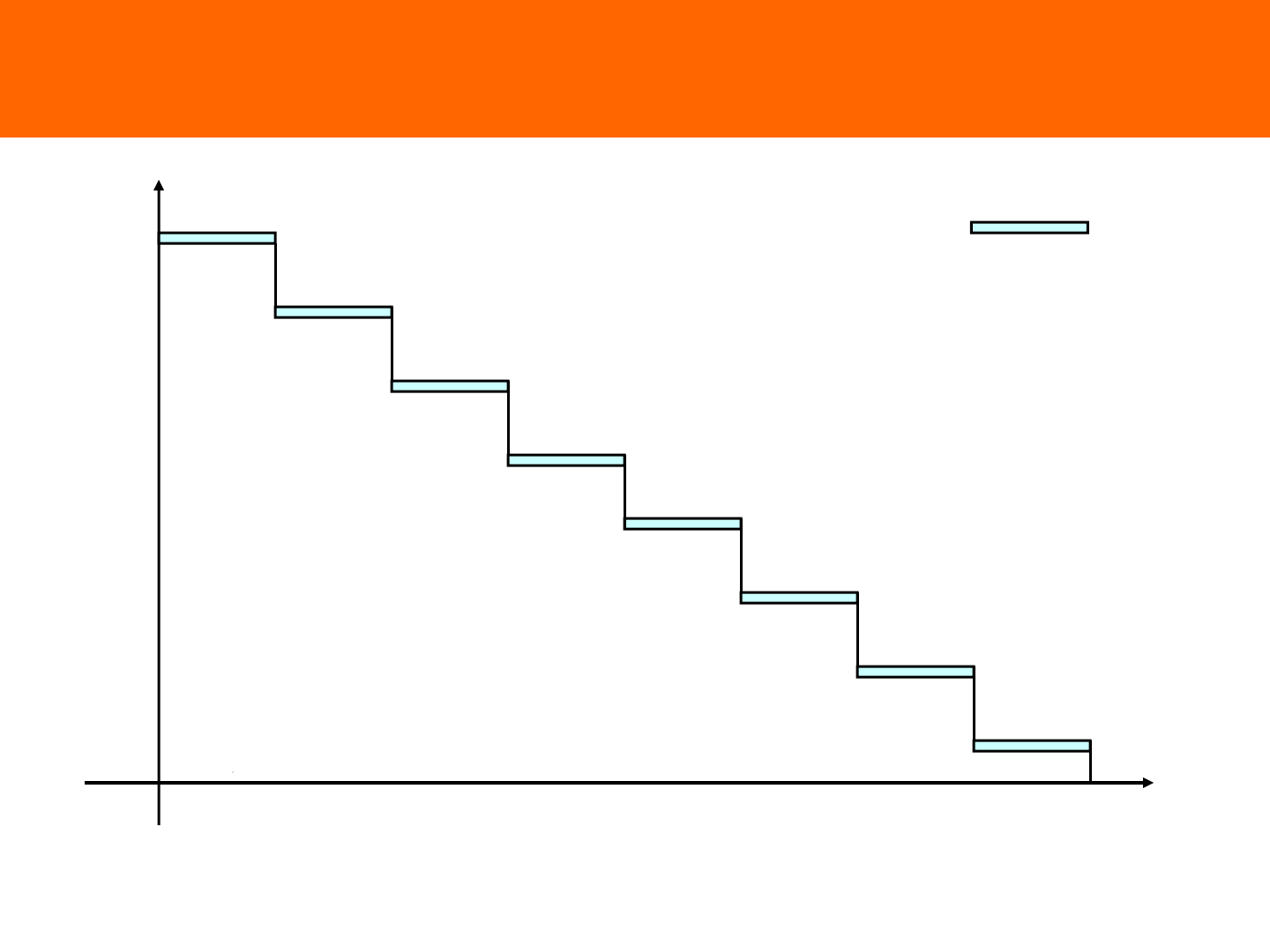
How To Sample & Mark A Packet?
quantized_Fb
7
# of bytes to
sample a packet
15 23 31 39 47 55 63
150KB
75KB
18.5KB
50KB
37.5KB
30KB
25KB
21.5KB
with certain margin of
Randomness
– How frequent the feedback is
depends on congestion level

5
QCN (A Brief Review)
- Reaction Point
Two counters: byte-counter and
timer cycle through independently;
Both reset by Fb < 0 signal
Fb < 0
signal
+
+
-
– Byte-Counter
• Fb < 0 resets byte-counter
• Stage counter is incremented whenever a
certain amount of data is accumulated
–Timer
• Fb < 0 resets timer
• Stage counter is incremented whenever a
certain amount of time has passed
– Rate Limter (RL)
• Depending the states of Byte-Counter’s and
Timer’s stage counters to decide rate adjustment
actions

6
Byte Counter
reset by Fb < 0 signal
expire_threshold = BC_LIMIT
Byte Counter
(incremented by bytes sent)
stage counter
si_bcount ++
expire
si_bcount <
FAST_RECOVERY_TH?
y n
expire_threshold
= BC_LIMIT
expire_threshold
= BC_LIMIT / 2

7
Timer
reset by Fb < 0 signal
expire_period = TIMER_PERIOD
Timer
(independent clock)
stage counter
timer_scount ++
expire
timer_scount <
FAST_RECOVERY_TH?
y n
expire_period =
TIMER_PERIOD
expire_period =
TIMER_PERIOD / 2

8
Rate Limiter State Diagram
Fb < 0 signal
Fast Recovery Stage
(FR)
min (si_bcount, timer_scount) <
FAST_RECOVERY_TH &&
max (si_bcount, timer_scount) >=
FAST_RECOVERY_TH ?
y
n
Active Increase Stage
(AI)
min (si_bcount, timer_scount) >=
FAST_RECOVERY_TH &&
max (si_bcount, timer_scount) >=
FAST_RECOVERY_TH ?
byte_counter or
timer expires
byte_counter or
timer expires
n
y
Hyper Active Increase
Stage (HAI)

9
Rate Changes
- Upon a Fb < 0 message
– Target Rate (TR) is decreased implicitly
• TR = Current Rate (CR)
– Current Rate (CR) is multiplicatively decreased
• CR = CR * (1 – Gd*|Fb|)

10
Rate Changes
- Upon byte_counter or timer expires
1) Fast Recovery
- TR = CR
- CR = (CR+TR)/2
2) Additive Increase
-TR = TR+R_AI; CR = (CR+TR)/2
3) Hyper Additive Increase (event numbered i = 1, 2, …)
- At the end of event number i:
TR = TR + (i*R_HAI); CR = (CR+TR)/2

11
Baseline #1

12
Simulation Parameters
• Traffic
– i.i.d. Bernoulli arrivals
– Uniform destination distribution (to all
nodes except self)
– Fixed frame size = 1500 B
•Switch
– VOQ with 2.4MB shared mem
– Partitioned memory per input, shared
among all outputs
– No limit on per-output memory usage
• Adapter
– RLT: VOQ and single; RR service
– One rate limiter per destination
– Egress buffer size = 1500 KB,
– Ingress buffer size = Unlimited
•QCN
–W = 2.0
– Q_EQ = 33 KB
– GD = 0.0078125
– Base marking: once every 150 KB
– Margin of randomness: 30%
–R
unit
= 1 Mb/s
– MIN_RATE = 10 Mb/s
– BC_LIMIT = 150 KB
– TIMER_PERIOD = 15 ms
– R_AI = 5 Mbps
– R_HAI = 50Mbps
– FAST_RECOVERY_TH = 5
– Quantized_Fb: 6 bits

13
Service Rate: 2.0Gbps
- Queue Size

14
Service Rate: 2.0Gbps
- Throughput

15
Baseline #2
2.

16
Link Throughput
- The Congested Link (n = 4)

17
- Congested Queue Size (n = 4)
# of drops: 245

Summary
• QCN is a congestion control mechanism for data
center Ethernet
• Congestion points send negative feedback signals
• Reaction point responds to congestion signals by
cutting its rate, lack of such signals would trigger
reaction point to increase its rate
– fast recovery, additive increase and hyper additive
increase.
