
HeaterKit
BM23608
INSTALLATIONINSTRUCTIONS
HeaterKit
M17235814APR20(ENGLISH)
HPX,HPX615E,HPX815E,XUV620i,XUV625i,XUV825E,
XUV825i,XUV825iS4,XUV825M,XUV825MS4,
XUV855D,XUV855DS4,XUV855E,XUV855M,XUV855M
S4Gator™UtilityVehicles
JohnDeereHoriconWorks
M172358(14APR20)
PRINTEDINU.S.A.
COPYRIGHT©2020
DEERE&COMPANY
Moline,Illinois
Allrightsreserved.
AJohnDeereILLUSTRUCTION™Manual
PreviousEditions
Copyright©2013,2016,2018
M172358-19-14APR20

BM23608
OUMX068,00003FD-19-22JAN13-1/1
BVVMSIT,000021A-19-25MAR20-1/1
FENAFNX,0000155-19-13APR20-1/1
Grease
NOTE:Asuitabledielectricgreasemustbeapplied
wheninstallingthiskit.YoucanpurchaseMPG2
greasefromyourlocalJohnDeeredealer.
PartsinKit
HeaterKit
QuantityDescription
1
T-tting(A)
1
BleederT-tting(B)
1
Heater/BlowerUnit
1
PaddedHeaterCover
1
FloorCover(withhardware)
1
HeaterRetainingPanel(withhardwareand
electricalharnesses)
2
Grommet
2
HoseClamp,1-1/2inch
4
HoseClamp,1inch
1HoseBracket
2HoseProtector
1
ShortExtensionHeaterHoseSection
1PopRivet
8Washer,M8
2Washer,M6
2Locknut,M6
1
Self-threadingScrew
4HexHeadBolt,M6x16
3HexHeadBolt,M6x20
12
TieStrap
NOTE:Retaintheseinstallationinstructionswiththe
machineoperator’smanual.
MXT014968—UN—07JUL15
A—T-ttingB—BleederT-tting
NOTE:Somepartsmaynotbeuseddepending
uponyourmachinemodel.
AdditionalFittingKitPartsRequiredfor
Installation
Thettingsusedtoconnecttheheaterhosestothe
enginearenotthesameforthethreetypesofengines.
Oneofthreefollowingkitsisrequiredtocompletethis
HeaterKitinstallation:
•
VGB10547includesanL-shapedttingandO-ringfor
installationonXUV625i.
•
BM23509includesaT-ttingandtwoclampsfor
installationonXUV825i,XUV825EandXUV825M.
•
VGB10548includesastraightttingwiththread
tapeappliedforinstallationonXUV855D,XUV855E,
XUV855M,HPX815EandHPXDiesel.
M172358(14APR20)
1
041420
PN=3
BM23608
MX88017,0000007-19-17OCT19-1/1
FENAFNX,0000156-19-13APR20-1/6
FENAFNX,0000156-19-13APR20-2/6
ContinuedonnextpageFENAFNX,0000156-19-13APR20-3/6
ParkingSafely
Parkthemachinesafely.SeeParkingSafelyinyour
Operator’sManual.
DrainEngineCoolant
NOTE:Drainenginecoolantaspertheinstructions
inyourmachineoperator'smanual.
HPXGasandHPX615E
1.Loosendrainscrew(A)ontheleftsideofengine,and
draincoolantintopan.
2.Afterallcoolanthasdrained,tightendrainscrew(A).
A—DrainScrew
MXT008978—UN—12SEP13
HPXDieselandHPX815E
1.Loosendrainscrew(A)behindthefuellter(B),and
draincoolantintopan.
2.Afterallcoolanthasdrained,tightenthedrainscrew
(A).
A—DrainScrew
B—FuelFilter
MXT015081—UN—15JUL15
XUV625i
1.Removedrainscrew(A)atbottomofthethermostat
housing,anddraincoolantintopan.
2.Afterallcoolanthasdrained,tightenthedrainscrew
(A).
A—DrainScrew
MXT008980—UN—12SEP13
M172358(14APR20)
2
041420
PN=4

BM23608
FENAFNX,0000156-19-13APR20-4/6
ContinuedonnextpageFENAFNX,0000156-19-13APR20-5/6
XUV825i,XUV825EandXUV825M
1.Cuthose(A)atlocation(B).
A—Hose
B—Location
C—UpperHose
MXT008981—UN—12SEP13
PictureNote:Upperhose(C)raisedforbetterview.
XUV855D,XUV855EandXUV855M
1.Removeandretainthebolt(A)thatsecuresdipstick
tubebracket,andfuellter.
NOTE:Fuellterassemblycanbemovedoutoftheway
withoutdisconnectingfuellines.Itcanbehelpfulto
securefuellterwhenworkingwiththecoolantdrain.
Donotmovethedipsticktubemorethan
necessarytoavoiddamagingoftheO-ring
atthebaseofthetube.
2.Pivotdipsticktube(B),andmovefuellterassembly
outofthewaytoreachthedrainscrewbehindand
belowthefuellter.
MXT008982—UN—12SEP13
A—BoltB—DipstickTube
M172358(14APR20)
3
041420
PN=5
BM23608
FENAFNX,0000156-19-13APR20-6/6
FENAFNX,0000144-19-10APR20-1/9
ContinuedonnextpageFENAFNX,0000144-19-10APR20-2/9
3.Removedrainscrew(A),andallowcoolanttodrain.
4.Whencoolanthasdrained,removehexdrain
extension(B)fromblock.
A—DrainScrew
B—DrainExtension
MXT008983—UN—12SEP13
InstallHeaterUnitandFloorPanel
1.Removeanddiscardtwoscrews(A),andstorage
compartment(B).
A—Screw(2used)B—StorageCompartment
MXT008984—UN—12SEP13
2.Removeandretainhardware(A)attachingthelower
bracket(B)totheheaterunit(C).
A—Hardware
B—LowerBracket
C—HeaterUnit
APY30680—UN—31MAR20
M172358(14APR20)
4
041420
PN=6

BM23608
FENAFNX,0000144-19-10APR20-3/9
ContinuedonnextpageFENAFNX,0000144-19-10APR20-4/9
3.Installheaterunit(A)asshown(withhosesandhose
coversattached),withthelowermountingplate(B)
oftheunitpositionedundergrabhandle(C).Make
surethattherearofthemountingplaterestingonthe
machinefender(D).
A—HeaterUnit
B—LowerMountingPlate
C—GrabHandle
D—Fender
MXT008986—UN—12SEP13
4.Installwireharnessandheaterretainingpanel(A)as
shownwiththestep(B)atthefrontofapanelontop
ofgrabhandle(C).
5.Tilttheheaterunitup,alignouterholesatthefrontof
theheaterplatewithlowerclipsnuts(D)ontheheater
retainingpanel.Installtwohexheadbolts(E),and
M6washers.
A—HeaterRetainingPanel
B—Step
C—GrabHandle
D—ClipNut(2used)
E—HexHeadBolt,M6x16(2
used)
MXT015085—UN—21JUL15
M172358(14APR20)
5
041420
PN=7

BM23608
FENAFNX,0000144-19-10APR20-5/9
FENAFNX,0000144-19-10APR20-6/9
ContinuedonnextpageFENAFNX,0000144-19-10APR20-7/9
6.Looselyinstalllowerbracket(A)totheheaterunitwith
thehardwareremovedearlier.
7.Adjustlowerbrackettopositionheaterunitwiththe
backofbrackettightagainstthefootdeck,andtighten
hardware.
8.Holdbracketrmlyinpositionagainstthefootdeck
andmarkfootdeckatcenterofthelowerhole(B)in
thebracketfordrilling.
9.Centerpunchanddrilla5mm(3/16in)holethrough
thefootdeckatmark.
10.Installaself-threadingscrew,andM6washerthrough
thebracketintothefootdeck.
A—LowerBracketB—LowerHole
MXT008988—UN—12SEP13
11.Presstopofheaterretainingpanel(A)backtoward
theheaterunit(B).Donotforcethepanelbackwards
excessivelysothatthepanelbends.
12.Holdtheupperbracket(C)oftheretainingpanel
upwardagainstthedashpanel.
13.Usingthetwoholesintheupperbracketasaguide,
drilltwo4mm(5/32in)holes(D)throughthedash
panel.Later,thistwoholesareusedfortheinstallation
ofpoprivets.
A—Panel
B—HeaterUnit
C—UpperBracket
D—Hole
MXT008989—UN—12SEP13
14.Removeplasticplugsfromtwoholesatthebaseof
therightsidecloseoutpanel(A),andinstallhose
grommets(B).
A—Panel
B—Grommet(2used)
MXT008990—UN—13SEP13
M172358(14APR20)
6
041420
PN=8

BM23608
FENAFNX,0000144-19-10APR20-8/9
FENAFNX,0000144-19-10APR20-9/9
ContinuedonnextpageFENAFNX,0000145-19-10APR20-1/5
15.Lubricateheaterhoses(A)withsoapywaterorrubber
lubricant,andinstallhosesthroughgrommets(B).Pull
hosesbackthroughgrommets,leavingslackfornal
hoserouting.
16.Determinewhichheaterhoseisconnectedtothe
shutoffvalve,andmarkortagthathoseattheoutside
ofthecloseoutpanelforfuturereference.
A—Hose(2used)B—Grommet(2used)
MXT008991—UN—13SEP13
17.Positionoorcover(A)overhosesonthefootdeck.
Adjusthoselengthasnecessaryforproperrouting.
Donotinstallhardware.
A—FloorCover
MXT008992—UN—12SEP13
InstallFittingsandHoses(HPXGasand
HPX615E)
1.Unplugwiringleadconnector(A)fromthetemperature
sensor(B).
2.Removeandretaintemperaturesensor(B),and
sealingwasher.
A—WiringLeadConnectorB—TemperatureSensor
MXT008993—UN—12SEP13
M172358(14APR20)
7
041420
PN=9

BM23608
FENAFNX,0000145-19-10APR20-2/5
ContinuedonnextpageFENAFNX,0000145-19-10APR20-3/5
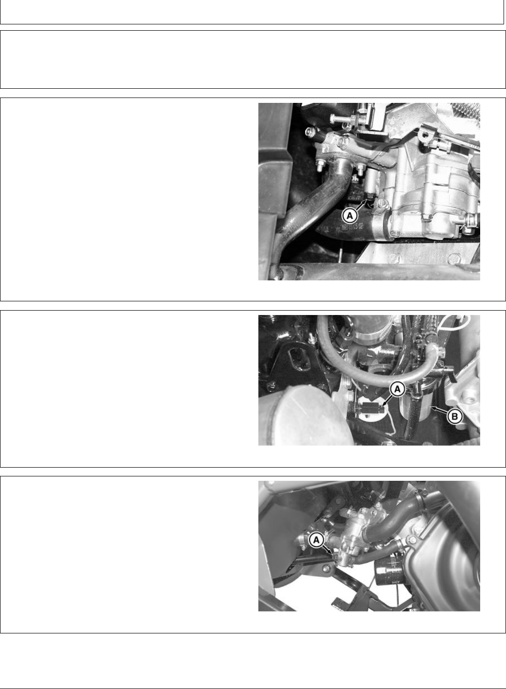
NOTE:DonotapplythreadsealanttoeithertheT-adapter
orthetemperaturesensorwheninstalling.
3.Installbrasssealingwasher(A)onthethreadedtting
(B).
NOTE:ThethreadedttingontheT-adapter(C)accepts
a3/8inHexkeywrenchusedfortightening.
4.InstallT-adapterandbrasssealingwasherinthe
cylinderheadport.Positionhosenipple(D),and
tightenthethreadedtting.
Specication
Threaded
Fitting—Torque ..............................................................................75N·m
(55lb·ft)
5.Installoriginaltemperaturesensor(E),andsealing
washer(F)inT-adapter.
Specication
Threaded
Fitting—Torque ..............................................................................60N·m
(44lb·ft)
6.Plugwiringleadconnectortothetemperaturesensor
terminal.
MXT015083—UN—21JUL15
A—BrassSealingWasher
B—ThreadedFitting
C—T-adapter
D—HoseNipple
E—TemperatureSensor
F—SealingWasher
7.Cutthroughreturnradiatorhose(A),andinstallT-tting
(B)includedinthiskitwithtwohoseclamps(C).
A—RadiatorReturnHose
B—T-tting
C—HoseClamp,1-1/2in(2
used)
MXT008995—UN—13SEP13
M172358(14APR20)
8
041420
PN=10

BM23608
FENAFNX,0000145-19-10APR20-4/5
FENAFNX,0000145-19-10APR20-5/5
8.Routeheaterhosesfromtherightsidecloseoutpanel,
betweenanupperframemember(A),andlowerframe
member(B),andintoenginecompartment.
A—UpperFrameMemberB—LowerFrameMember
MXT008996—UN—12SEP13
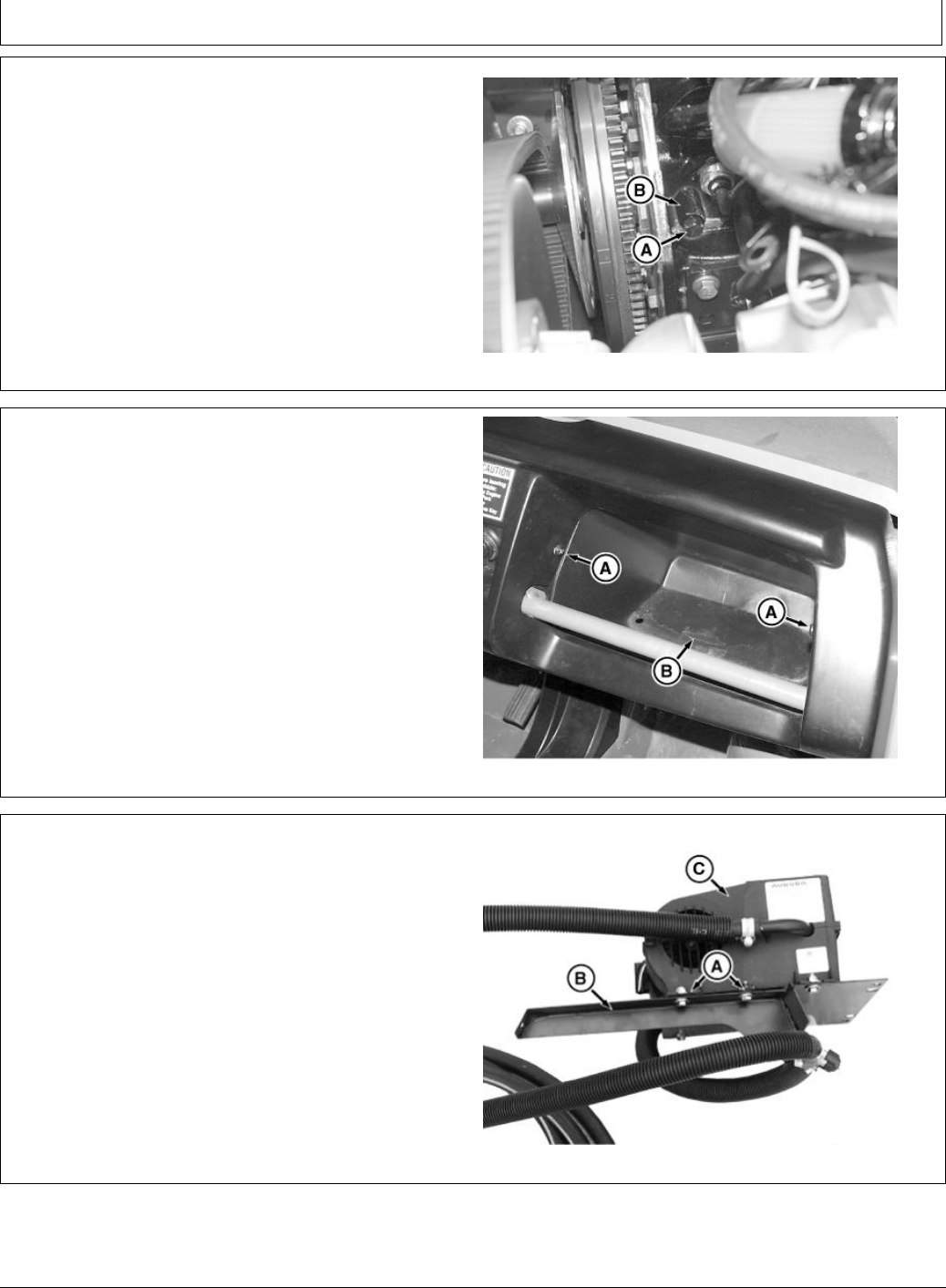
9.Routeheatershutoffvalvehose(A)overengine,to
thehosenipple(B)onT-adapter.
10.Verifythatheatershutoffvalvehose(A)hasenough
lengthforslackandforsafelysecuringtoother
components.T otthehosenipple(B),cuthoseto
properlength.Installhosenipple(B)usinga25.4mm
(1in)hoseclamp.
11.Cutheatershutoffvalvehose(A)approximately100
mm(4in)fromendofthehosenipple(B).
12.Withthebleederscrew(C)pointedup,installbleeder
T-ttingincludedwiththiskitusinga25.4mm(1in)
hoseclamp.
13.Routeremainingheatershutoffvalvehose(A)over
thecoolantpressurehosetobleederT-tting.
14.Verifythatheatershutoffvalvehose(A)hasenough
lengthforslackandforsafelysecuringtoother
components.T otbleederT-tting,cuthosetoproper
length.InstallonbleederT-ttingusinga25.4mm(1
in)hoseclamp.
MXT008997—UN—13SEP13
A—HeaterShutoffValveHose
B—HoseNipple
C—BleederScrew
M172358(14APR20)
9
041420
PN=11

BM23608
FENAFNX,0000146-19-10APR20-1/5
ContinuedonnextpageFENAFNX,0000146-19-10APR20-2/5
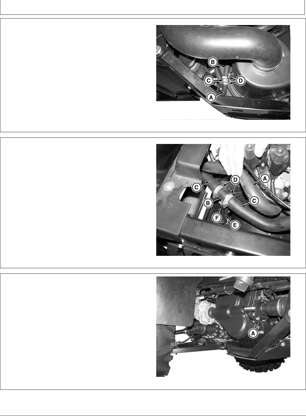
InstallFittingsandHoses(HPXDieseland
HPX815E)
1.Removedraintting(A)fromtheengineblockatthe
leftsideofmachine.Replacewiththestraighttting
(B)includedinadditionalttingkitVGB10548.
A—DrainFitting
B—StraightFitting
MXT008998—UN—12SEP13
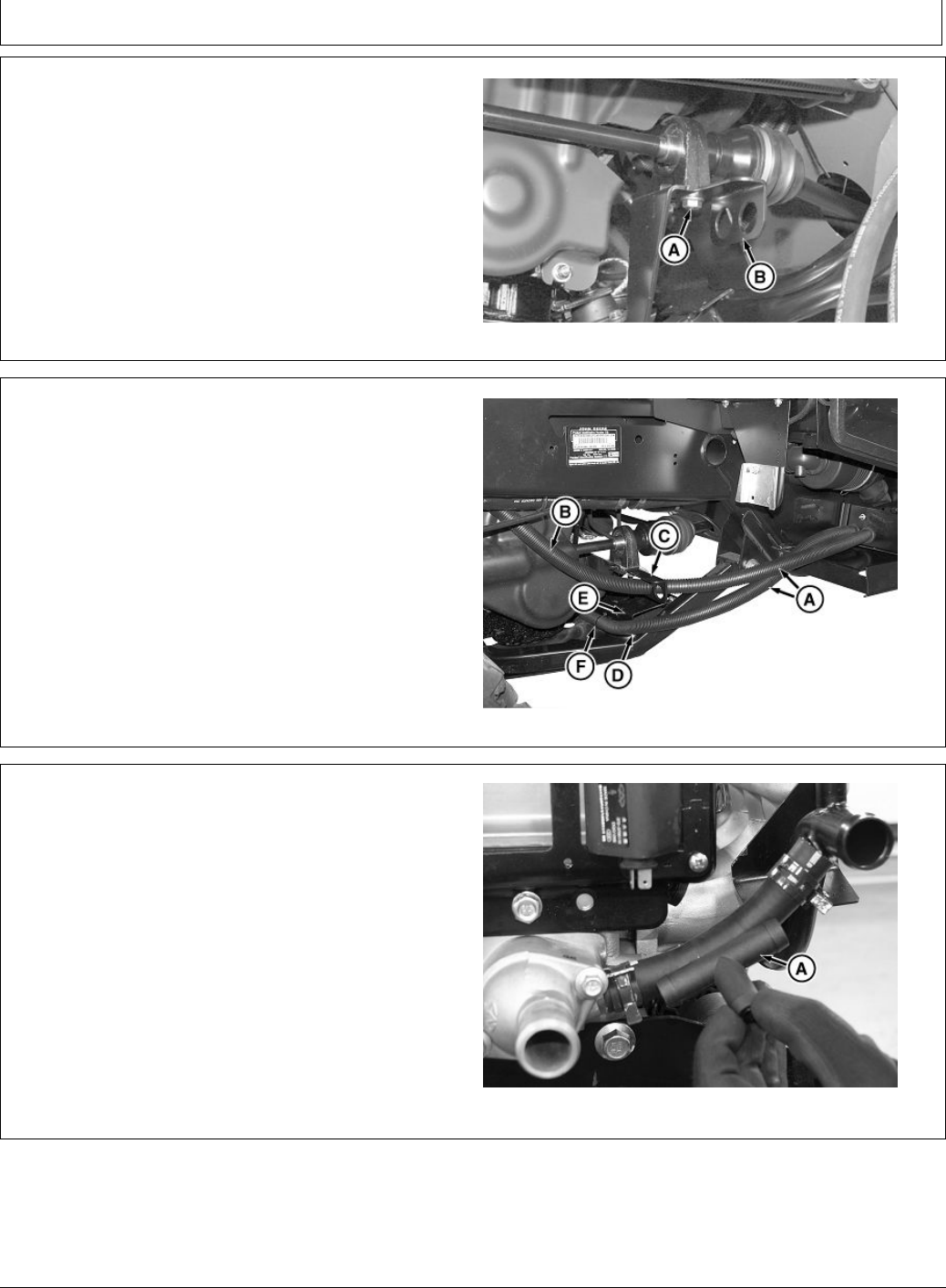
2.Locateexistingcoolantreturnhose(A)thatconnects
totheengineblockbehindthethermostat.Cutthrough
thehoseintheareashown(B)neartheprotrusion
(C)ofthebeltguard.
A—ReturnHose
B—PointMarked
C—Protrusion
MXT008999—UN—12SEP13
M172358(14APR20)
10
041420
PN=12

BM23608
FENAFNX,0000146-19-10APR20-3/5
ContinuedonnextpageFENAFNX,0000146-19-10APR20-4/5
3.InstallT-tting(A)includedwiththiskitonthehose
withtwo1-1/2inchhoseclamps.
A—T-tting
MXT009000—UN—12SEP13
PictureNote:Fittingshownwithheaterhoseconnected.
4.Routeheaterhosesfromtherightsidecloseoutpanel,
betweenanupperframemember(A),andlowerframe
member(B)intoenginecompartment.
A—UpperFrameMemberB—LowerFrameMember
MXT009002—UN—12SEP13
M172358(14APR20)
11
041420
PN=13

BM23608
FENAFNX,0000146-19-10APR20-5/5
ContinuedonnextpageBVVMSIT,000021F-19-31MAR20-1/8
5.Routeheatershutoffvalvehose(A)overtheengineto
thestraightttinginstalledintheengineblockdrain.
6.Verifythatheatershutoffvalvehose(A)hasenough
lengthforslackandforsafelysecuringtoother
components.Cuttoproperlengthforstraighttting
installation.Installstraightttingwitha1inhoseclamp.
7.Cutheatershutoffvalvehose(A),andinstallbleeder
T-tting(B)includedwiththiskitsothatbleederscrew
(C)ispointedup.Securewith1inchhoseclamp.
8.Routeremainingshutoffvalveheaterhoseoverthe
coolantpressurehosetobleederT-tting.
NOTE:Beforecuttingheatershutoffvalvehose,verify
thatthehosehasenoughlengthforslackand
forsafelysecuringtoothercomponents.
9.Cutheatershutoffvalvehose(A),andinstallon
bleederT-tting(B)with1inchhoseclamp.
10.Installtiestrapsonheaterhoses,asneeded,to
protecthosesagainstcontactwithmovingparts.
MXT009003—UN—12SEP13
A—HeaterShutoffValveHose
B—BleederT-tting
C—BleederScrew
InstallFittingsandHoses(XUV620i,XUV625i)
1.LocatetheT-tting(A)includedinthiskitandcutthe
threehoseendsattheedgeofthestep-downradius
(B),asshown.
2.DeburrT-ttingasnecessaryaftercutting.
A—T-ttingB—Step-DownRadius
MXT009004—UN—12SEP13
M172358(14APR20)
12
041420
PN=14

BM23608
BVVMSIT,000021F-19-31MAR20-2/8
ContinuedonnextpageBVVMSIT,000021F-19-31MAR20-3/8
3.Cuttwosectionsofthehoseprotector(A)
approximately355mm(14in)long,andslidethem
overthetwoheaterhosesbehindthecloseoutpanel.
4.Routebothheaterhosesthroughtheopeninginthe
driveshaftsupportbracket(B).
5.Continueroutingthehose(C),fromtheheatervalve,
behindthedriveshaftanduptothetopoftheengine.
6.Continueroutingthereturnhose(D)fromthedrive
shaftsupportbracketunderthefrontoftheengine
towardthethermostathousing.
7.Positionbothhosesforbestroutingfromthecloseout
panelthroughthedriveshaftbracket.Repositionthe
hoseprotectorsformaximumprotectionfortheouter
hose,innerhoseatthedriveshaftbracket,andthe
hardware(E)attheframeconnection.
8.Installtiestraps(F)aroundthetwohoses,intwo
places.
MXT009005—UN—12SEP13
A—HoseProtector
B—DriveShaftSupportBracket
C—Hose
D—ReturnHose
E—Hardware
F—TieStrap
NOTE:InstallationofthemodiedT-tting(A)requires
thethermostattoenginehosetobecut.
9.Locatethermostattotheenginehoseandmarkcutline
(B).Markthreeorientationlines(C)toaidininstallation.
A—T-tting
B—CutLine
C—Orientationline
MXT009006—UN—12SEP13
PictureNote:NoteorientationofT-ttingandmarkedhose.
M172358(14APR20)
13
041420
PN=15

BM23608
BVVMSIT,000021F-19-31MAR20-4/8
BVVMSIT,000021F-19-31MAR20-5/8
ContinuedonnextpageBVVMSIT,000021F-19-31MAR20-6/8
10.Removeandretaintwobolts(A)fromthethermostat
housingandbracket.
11.Removethetwoclampsandthermostathose.Cutthe
thermostathoseatthemarkedcutline.
NOTE:ThesmallhoseendontheT-ttingincludedinthis
kitisangledparalleltotheenginecover.Routethe
hosebetweentheenginecover,andclutchcover.
12.InstallT-tting,andtwo1-1/2inchhoseclampson
thethermostathose.
NOTE:Theadditionalhoseprotectorisneeded
wheretheheaterhoseisroutedbetweenthe
engineandclutchcover.
13.Installasectionofthehoseprotectorapproximately
254mm(10in)long,ontotheendoftheheaterreturn
hose.Theninstallthehoseanda1inhoseclamp
ontheT-tting.
MXT009007—UN—12SEP13
A—Bolt
14.Installthermostathose(A)withoriginalhoseclamps.
CheckalignmentofhosesandT-tting,adjustif
necessary.Tightentheallclamps.
15.Slidehoseprotectorontheheaterhose,uptoclamp
atT-tting.
16.Installthermostathousingtobracketwithoriginalbolts.
17.Installheaterhose(B)totheframebracketatthefront
ofanenginewithtiestrap(C).
A—ThermostatHose
B—HeaterHose
C—TieStrap
MXT009008—UN—13SEP13
PictureNote:Correctorientationofassembledcomponents.
Shownwithoptionalhighoutputalternator.
18.Removeandretaintheplug(A),andsealingwasher
fromtherearcylinderhead.
A—Plug
MXT009009—UN—12SEP13
M172358(14APR20)
14
041420
PN=16

BM23608
BVVMSIT,000021F-19-31MAR20-7/8
BVVMSIT,000021F-19-31MAR20-8/8
19.Installbrasssealingwasher(A)onthethreadedtting
(B)oftheT-adapter(C).
NOTE:ThethreadedttingontheT-adapter(C)accepts
a3/8inchwrenchusedfortightening.
20.InstalltheT-adapter(C)andbrasssealingwasher
(A)intothecylinderheadportwheretheplug(D)
wasremovedearlier.Positionthehosenipple(E)as
shownandholdadapterinplacewhiletighteningthe
threadedttingwitha3/8inchwrench.Tightenthe
threadedtting.
Specication
Threaded
Fitting—Torque ..............................................................................75N·m
(55lb·ft)
21.Installtheplugwiththesealingwasher(removed
earlier)intotheopenportoftheT-adapter(C),Tighten
theplug.
Specication
Threaded
Fitting—Torque ..............................................................................60N·m
(44lb·ft)
MXT015084—UN—21JUL15
A—BrassSealingWasher
B—ThreadedFitting
C—T-adapter
D—Plug
E—HoseNipple
22.Finishroutingoftheheaterhose(A)overtothehose
nippleontheT-adapter,underthewiringharness,as
shown.Checkroutingforeliminatingtheexcessive
slack,trimhoselengthifnecessary.Connecttohose
nippletotheT-adapterwith1inchhoseclamp.
23.Locatethehighspotontheheaterhoseandcutthe
hoseinthatspot.Installtwo1inchhoseclamps
ontothecutends.TheninstalltheT-ttingbleeder
(B)includedinthiskit.Rotatethettingsothatthe
bleederscrew(C)isfacingupandtightentheclamps.
24.Secureheaterhosetocoolanthoseatthefrontof
ywheelcoverwithtiestrap.
A—HeaterHose
B—T-ttingBleeder
C—BleederScrew
MXT009011—UN—12SEP13
M172358(14APR20)
15
041420
PN=17

BM23608
FENAFNX,0000147-19-10APR20-1/7
FENAFNX,0000147-19-10APR20-2/7
ContinuedonnextpageFENAFNX,0000147-19-10APR20-3/7
InstallFittingsandHoses(XUV855D,
XUV855EandXUV855M)
IMPORTANT:Avoiddamage!Becarefulnottomove
orchangethealignmentofthepillowblock
wheninstallingthehosebracket.
1.Removeandretaintheouterdriveshaftpillowblock
retainingbolt(A)fromthebracket.
A—Bolt
MXT009012—UN—12SEP13
NOTE:Donotmovepillowblockduringbracket
installation.Ensurethatthebracketisparallel
withthepillowblock,asshown.
2.Installhosebracket(B)underthepillowblockbracket
withapillowblockretainingbolt(A),removedearlier.
Tightenthebolt.
Specication
Bolt—Torque ..................................................................................73N·m
(54lb·ft)
A—Bolt,PillowBlockRetainingB—HoseBracket
MXT009013—UN—12SEP13
3.Cuttwopiecesofthehoseprotector(A)approximately
355mm(14in)long.Slidethemoverthetwoheater
hosesbehindthecloseoutpanelandthroughthehose
bracket(B).Thelongerhose,comingfromtheheater
valve,usestheouterbrackethole.Theshorterreturn
hoseusestheinnerbrackethole.
4.Adjustthehoseprotectorssothatafewinchesof
thehoseprotectorareontherearsideofthehose
bracket,asshown.
A—HoseProtectorB—HoseBracket
MXT009014—UN—13SEP13
M172358(14APR20)
16
041420
PN=18

BM23608
FENAFNX,0000147-19-10APR20-4/7
FENAFNX,0000147-19-10APR20-5/7
ContinuedonnextpageFENAFNX,0000147-19-10APR20-6/7
5.Locatetheexistingcoolanthose(A)abovethedrive
shaftandparkbrakearm.T emporarilyroutetheinner
heaterhose(returnhose)fromthehosebracketup
betweenthedriveshaftandparkbrakearmtocoolant
hose.Allowadequateclearancebehindthedriveshaft
pillowblock.Markacutline(B)onthecoolanthose.
6.Removecoolanthoseandcutthehoseatthemarked
cutline.
7.PositionandorientatetheT-ttingincludedinthis
kitsothatsmallhoseendpointsdownward.Install
T-ttingwithtwo1-1/2inchhoseclamps.
A—CoolantHoseB—CutLine
MXT009015—UN—12SEP13
8.Routetheheaterreturnhose(A)uptoT-tting(B)
includedinthiskitbetweendriveshaftandparkbrake
arm.Keephoselengthasshortaspossiblewithout
kinkingatbend.Cutthehosetolengthandinstallon
T-ttingwith1inchhoseclamp(C).
9.AdjustT-ttingsothatitanglesslightlyoutwardfor
maximizehoseclearance.Tightenthesmallhose
clamprst,thenmovethetwohoseclamps(D)in
positionandtightenthem.
A—ReturnHose
B—T-tting
C—Clamp,1in
D—Clamp,1-1/2in
MXT009016—UN—12SEP13
10.Installthestraighttting(A)includedinadditional
ttingkitVGB10548intothedrainscrewport.Tighten
thetting.
11.Cutasectionofhose(B)includedinthiskit
approximately508mm(20in)long.Installonthe
straightttingwith1inchhoseclamp.
12.Cutasectionofthehoseprotectorapproximately305
mm(12in)longandinstallonthehoseuptoclamp.
13.Reinstallfuellterassemblyanddipsticktubeonto
theiroriginalpositionswithpreviouslyremovedbolt.
A—StraightFitting
B—Hose
MXT009017—UN—12SEP13
M172358(14APR20)
17
041420
PN=19

BM23608
FENAFNX,0000147-19-10APR20-7/7
FENAFNX,0000148-19-10APR20-1/7
ContinuedonnextpageFENAFNX,0000148-19-10APR20-2/7
14.InstallbleederT-tting(A)includedinthiskittothe
bleederhose(B)with1inchhoseclamp.Donot
tightentheclamp.
15.Routetheheaterhose(C)andheaterreturnhose
betweendriveshaftandparkbrakearm,tothetopof
anengine.Installtiestraparoundhosesnearbleeder
T-tting.
16.RoutethehosewithbleederT-ttingalongthereturn
hoseasshown.Positiontheheaterhoseatbleeder
T-tting.
17.Adjustthehosesuntilthebleederscrew(D)isatthe
highestpointofreturnhose.Trimexcessheaterhose
whenthebleederhoseandheaterhoseareconnected.
18.InstallheaterhoseonbleederT-tting.Tightenboth
hoseclamps.
19.Installbleederandheaterhosestotheintakehose(E)
withthetwotie-straps(F)asshown.Tiestrapsmustbe
assembledtoeachothertocreateonelongtiestrap.
MXT014970—UN—11AUG15
A—BleederT-tting
B—BleederHose
C—HeaterHose
D—BleederScrew
E—IntakeHose
F—TieStrap
InstallFittingsandHoses(XUV825i,XUV825E
andXUV825M:SerialNumber—80000)
NOTE:Thesemachineshavezinc-plated(gold
colored)solidcoolanttube.
IMPORTANT:Avoiddamage!Becarefulnottomove
orchangethealignmentofthepillowblock
wheninstallingthehosebracket.
1.Removeandretainouterdriveshaftpillowblock
retainingbolt(A)frombracket.
A—PillowBlockRetainingBolt
MXT009019—UN—12SEP13
NOTE:Donotmovepillowblockduringbracket
installation.Bracketmustbeparallelwith
thepillowblock,asshown.
2.Installhosebracket(B)underthepillowblockbracket
withthepillowblockretainingbolt(A).Tightenthebolt.
Specication
Bolt—Torque ..................................................................................73N·m
(54lb·ft)
A—PillowBlockRetainingBoltB—HoseBracket
MXT009020—UN—12SEP13
M172358(14APR20)
18
041420
PN=20

BM23608
FENAFNX,0000148-19-10APR20-3/7
FENAFNX,0000148-19-10APR20-4/7
ContinuedonnextpageFENAFNX,0000148-19-10APR20-5/7
3.Usetwopiecesofthehoseprotector(A),andslide
themoverthetwoheaterhosesbehindthecloseout
panel.
4.Installtheouterheaterhose(B)throughtheinnerhole
onthehosebracket(C).Routehoseoverthetopof
theengineasshown.
5.Installtheinnerheaterhose(D)downneartheframe
plate(E).Securehosewiththetiestrap(F)tothe
frameplate.
A—HoseProtector
B—OuterHeaterHose
C—HoseBracket
D—InnerHeaterHose
E—FramePlate
F—TieStrap
MXT009021—UN—13SEP13
6.Locatecoolanthoserunningparalleltovalvecover.
Trim3inchesfromtheendofsmalldiameterhose(A).
A—SmallDiameterHose
MXT009309—UN—21SEP13
7.Installlargediameterhose(A)onT-tting(B)included
inthiskit.InstallbleederT-tting(C)includedinthis
kitontoendofthecuthose(D).
8.Routeouterheaterhose(E)(hoseleadingtoengine)
aroundthefrontofbracket(F).ConnecttoT-tting
withclamps.
A—LargeDiameterHose
B—T-tting
C—T-tting,Bleeder
D—CutHose
E—OuterHeaterHose
F—Bracket
MXT009310—UN—21SEP13
M172358(14APR20)
19
041420
PN=21
BM23608
FENAFNX,0000148-19-10APR20-6/7
FENAFNX,0000148-19-10APR20-7/7
ContinuedonnextpageFENAFNX,0000157-19-13APR20-1/7
9.Routeinnerheaterhose(A)aroundtoleftsideof
machine.Cuta205mm(8in)pieceofradiatorhose
(B)fromshortextensionheaterhoseincludedinthis
kit.Connectwithextensionconnector(C)andtwo
crimpclamps(D).
A—InnerHeaterHose
B—RadiatorHose
C—Connector
D—CrimpClamps
MXT009024—UN—12SEP13
NOTE:Ifnecessary,haveanassistantholdupperradiator
hose(A)awayfromareawheninstallingT-tting
(B)includedinadditionalttingkitBM23509.
10.InstallT-tting(B)ontohoses(C)withtwoclamps(D).
11.Installshortextensionpieceofhose(E)ontothe
bottomofT-tting(B)withclamp(F).
A—UpperRadiatorHose
B—T-tting
C—Hoses
D—Clamp
E—Hose
F—Clamp
MXT009025—UN—13SEP13
InstallFittingsandHoses(XUV825i,XUV825E
andXUV825M:SerialNumber80001—)
NOTE:Thesemachineshaveablacksolidcoolanttube.
IMPORTANT:Avoiddamage!Becarefulnottomove
orchangethealignmentofthepillowblock
wheninstallingthehosebracket.
1.Removeandretainouterdriveshaftpillowblock
retainingbolt(A)frombracket.
A—PillowBlockRetainingBolt
MXT009019—UN—12SEP13
M172358(14APR20)
20
041420
PN=22
BM23608
FENAFNX,0000157-19-13APR20-2/7
FENAFNX,0000157-19-13APR20-3/7
ContinuedonnextpageFENAFNX,0000157-19-13APR20-4/7
NOTE:Donotmovepillowblockduringbracket
installation.Bracketmustbeparallelwith
thepillowblock.
2.Installhosebracket(B)underthepillowblockbracket
withthepillowblockretainingbolt(A).Tightenthebolt.
Specication
Bolt—Torque ..................................................................................73N·m
(54lb·ft)
A—PillowBlockRetainingBoltB—HoseBracket
MXT009020—UN—12SEP13
3.Usetwopiecesofthehoseprotector(A)andslidethem
overthetwoheaterhosesbehindthecloseoutpanel.
4.Installtheouterheaterhose(B)throughtheinnerhole
onthehosebracket(C).Routehoseoverthetopof
theengineasshown.
5.Installtheinnerheaterhose(D)downneartheframe
plate(E).Securehosewiththetiestrap(F)tothe
frameplate.
A—HoseProtector
B—OuterHeaterHose
C—Bracket
D—InnerHeaterHose
E—FramePlate
F—TieStrap
MXT009021—UN—13SEP13
6.Trim1.25inchesfromthehoseforinstallationof
T-tting(A)includedinthiskitinareashown.
A—T-tting
MXT009307—UN—21SEP13
PictureNote:Shownwithengineremoved.
M172358(14APR20)
21
041420
PN=23

BM23608
FENAFNX,0000157-19-13APR20-5/7
FENAFNX,0000157-19-13APR20-6/7
FENAFNX,0000157-19-13APR20-7/7
7.InstallT-tting(A)andheaterhose(B)ontothehose
withclamps(C).Ifnecessary,installT-tting(A)by
looseningboltsonthesolidcoolantline,andthen
installtomanifold.
A—T-tting
B—HeaterHose
C—Clamp(3used)
MXT009308—UN—21SEP13
8.Routeinnerheaterhose(A)aroundtoleftsideof
machine.Cuta205mm(8in)pieceofradiatorhose
(B)fromtheshortextensionoftheheaterhosesection
includedinthiskit.Connectwithextensionconnector
(C),andtwocrimpclamps(D).
A—InnerHose
B—RadiatorHose
C—ExtensionConnector
D—CrimpClamp(2used)
MXT009024—UN—12SEP13
NOTE:Ifnecessary,haveanassistantholdupperradiator
hose(A)awayfromareawheninstallingT-tting
(B)includedinadditionalttingkitBM23509.
9.InstallT-ttingontohoses(C)withtwoclamps(D).
10.Installshortextensionpieceofhose(E)ontobottom
ofT-ttingwithclamp(F).
A—UpperRadiatorHose
B—T-tting
C—Hose
D—Clamp(2used)
E—Hose
F—Clamp
MXT009025—UN—13SEP13
M172358(14APR20)
22
041420
PN=24

BM23608
BVVMSIT,0000228-19-25MAR20-1/1
PreparetoBleedAirfromSystem(AllModels)
1.Recoverdrainedcoolantfromthedrainpanand
transfertocontainersasneededfortherellingsystem.
2.Placedrainpanbackundertheenginetorecover
coolantlostduringbleedprocedure.
3.Removeoorcover.
4.Removemountingscrewsfromheaterretainingpanel
andlowerbracket.
5.Removetheheaterunit(A)withhosesattached.
6.Placetheheaterunitontheoor.
7.Withtheopenshutoffvalve(B),llradiatorand
recoverytanktotheupperline.
A—HeaterUnit
B—ShutoffValve
MXT009026—UN—12SEP13
M172358(14APR20)
23
041420
PN=25

BM23608
BVVMSIT,0000223-19-31MAR20-1/1
BleedAirfromSystem(AllHPX)
NOTE:Monitorcoolantlevelinradiatorduringbleed
procedure.Makesurethatitdoesnotfalltoolow.
Addcoolantasperrequirementforpreventing
theairentryintothesystem.
1.Openbleedscrewonthegasolineengineintake
manifold(A),oronthedieselenginethermostat
housing(B),untiluidcomes,withnoairbubbles.
Closethebleedscrew.
2.Fillcoolantuptotheupperlineoftheradiator.
3.Openbleedscrew(C)onthebleedteeuntiluid
comesout,withnoairbubblesorsoundofair
escaping.Closethevalve.
4.Shakeheaterunitandheaterhosesfordislodgingthe
airthatistrapped.
5.Openbleedscrew(C)onthegasolineengineintake
manifold(A),oronthedieselenginethermostat
housing(B),untiluidcomes,withnoairbubbles.
Closethebleedscrew(C).
6.Fillcoolantuptotheupperlineoftheradiator.Secure
theradiatorcap.
NOTE:Occasionallyshaketheheaterandheaterhoses
astheengineiswarminguptohelpdislodge
anyairstilltrappedinthesystem.
7.Fillthecoolantuptothetoplineoftheoverowbottle.
8.Startandrunengineuntilfancycles.Ifoverheatlight
doesnotcomeon,unitisproperlybled.
IMPORTANT:AvoidDamage!Ifoverheatlightcomes
on-Shutoffengineandallowittocool.Make
surethattheoverowbottleisfull,asthesystem
pullscoolantfromoverowbottleduringcool
down,helpingtoeliminateairinthesystem.
Whenengineiscool,repeatbleedprocedure.
MXT009027—UN—12SEP13
PictureNote:Gasolineengineshown.
MXT009028—UN—12SEP13
PictureNote:Dieselengineshown.
A—IntakeManifold
B—ThermostatHousing
C—BleedScrew
M172358(14APR20)
24
041420
PN=26

BM23608
ContinuedonnextpageFENAFNX,0000158-19-13APR20-1/2
BleedAirfromSystem(XUVGasEngine)
IMPORTANT:Avoiddamage!Usingincorrectcoolant
mixturecandamagetheradiator:
•Donotoperateengineinabsenceof
coolantorwithplainwater.
•Useantifreezeapprovedforusein
aluminumengines.
•Donotexceeda50%antifreezemixture
forthecoolant.
•Donotpourcoolantorwaterintoradiator
whenengineishot.
•DonotaddStopLeakorotheradditives.
NOTE:JohnDeereCool-Gard™coolantisrecommended
whenaddingcoolanttothecoolingsystem.
Followtheinstructiononthecontainerfor
thecorrectmixtureratio.
XUV620i,XUV625i
1.Raisecargobox.
IMPORTANT:Avoiddamage!Donotremovewashers
fromtoporbottomofthebanjotting.
NOTE:Tomaintainanadequatelevelandpreventthe
airentryintothesystem,monitorcoolantlevelin
radiator,andaddcoolantifnecessary.
2.Loosenenginebleedbolt(A)atthebanjottingon
theintakemanifold(fourfullturnsfromtight).Donot
removebolt,orwashers(B)atthebanjotting.
3.Loosenthebleedscrew(C)atthebleedtee.Donot
removethescrew.
4.Dislodgeairfromthesystembyshakingheater,and
hoses.
5.Maintainthecoolantlevelintotheradiatorandllthe
radiatorwithcoolant,ifnecessary.
6.Allowcoolanttorunoutofbothbleedlocationsuntil
coolantisrunningclear,withnoairbubblesandno
soundsofairescaping.Closebothbleeders.
7.Fillradiatorandrecoverytanktotheupperline,and
secureradiatorcap.
MXT009029—UN—12SEP13
A—BleedBolt
B—Washer(2used)
C—BleedScrew
8.Startengineandrunatlessthanfullthrottletowarmup.
NOTE:Tomaintainanadequatelevel,monitorcoolant
levelintherecoverytankduringwarm-up,and
addcoolant,ifnecessary.Warmupphase
cantakeseveralminutes.
9.Runengineuntilcoolingfanstarts,shakeheaterand
hosesperiodicallytodislodgeair.
CAUTION:Avoidinjury!Radiatorcanbehot.
Donotreachdownfromthetopoftheradiator
tochecklowerhosetemperature.
10.Whenfancomeson,immediatelychecktemperature
ofcoolanthoseatbottomofradiator.
1.Ifthehoseiscold,shutofftheengineandlet
enginecool.Monitorcoolantlevelintherecovery
tankandaddasneeded.Whenengineiscool,
llradiatorandrecoverytanktoupperlinesand
securewithcaps.Thenrepeatbleedprocedure.
Shakehosesandheaterwhenbleeding.
2.Ifthehoseiswarm/hot,reduceenginespeedto
idle,andcontinuerunningmachineuntilfanshuts
off,thencyclesbackonagain.Ifnotemperature
warninglighthascomeon,systemisbledproperly.
Shutofftheengineandletcooldown,monitoring
coolantlevelintherecoverytank.Fillrecovery
tanktotheupperline,ifnecessary.
Cool-GardisatrademarkofDeere&Company
M172358(14APR20)
25
041420
PN=27

BM23608
FENAFNX,0000158-19-13APR20-2/2
XUV825i,XUV825EandXUV825M.
1.Raisecargobox.
2.Loosenbleedscrew(A)locatedinT-ttingconnecting
hoses(B).
3.Removeradiatorcapandaddrecommendedcoolant
mixturetoradiatoruntilcoolantrunsoutofthebleed
port.
4.Tightenthebleedscrew(A).
5.Addadditionalcoolantmixturetoradiatoruntilcoolant
runsoutoftheoverowportandintotherecoverytank.
6.Installradiatorcap.
IMPORTANT:Avoiddamage!Positionhoseslightly
abovebottomoftherecoverytank.Donotallow
thehosetocontactbottomoftherecoverytank
orbendupwardsoutofthecoolant.
7.Removerecoverytankcap,andaddcoolantmixture
totherecoverytankuntilitisapproximatelyhalffull.
8.Installrecoverytankcap.
IMPORTANT:Avoiddamage!Ifcoolanttemperature
indicatorcomesonwhileengineisrunning,stop
engineandaddmorecoolantmixturetoradiator.
9.Startandrunengineatmediumspeeduntilupper
andlowerradiatorhoseshavebecomewarm(10—15
minutes).Warmhosesindicatethatthethermostat
hasopenedandcoolantiscirculating.
10.Allowenginetocool.
11.Loosenbleedscrew(A),andallowairtobubbleout
untilairbubblesarenolongervisibleatthebleedport.
Tightenbleedscrewcompletely.
MXT009030—UN—12SEP13
A—BleedScrew
B—Hoses
12.Removeradiatorcapandaddrecommendedcoolant
mixturetoradiatoruntilcoolantrunsoutoftheoverow
port,andintotherecoverytank.
13.Installtheradiatorcap.
14.Runengineuntilcoolingfanstarts,indicatingthat
theengine,andcoolanthasreachedoperating
temperature.
15.Stopengineandremovethekey.
16.Allowenginetocoolandsuctionbackanyneeded
coolantfromtheoverowrecoverytank.Fillrecovery
tanktotheupperline,ifnecessary.
M172358(14APR20)
26
041420
PN=28

BM23608
BVVMSIT,0000225-19-31MAR20-1/1
ContinuedonnextpageBVVMSIT,0000226-19-25MAR20-1/2
BleedAirfromSystem(XUVDieselEngine)
NOTE:Monitorcoolantlevelinradiatorduringbleed
procedure.Makesurethatitdoesnotfalltoo
low.Addcoolantasperrequirementandprevent
theairentryintothesystem.
1.Openthermostathousingbleedscrew(A)andbleed
screw(B)onbleedteefourturns.
2.Dislodgeairfromthesystembyshakingheaterand
hoses.Allowamplecoolanttorunthroughsystem
whenbleeding.
3.Maintainadequatelevelofcoolantinradiatorandadd
coolant,ifnecessary.
4.Whenclearcoolantiscomingfrombothlocations,and
noairbubblesorsoundsofairescaping,tightenboth
bleedscrew(B).
5.Fillradiatorandcoolantrecoverytanktotheupper
line,andsecureradiatorcap.
NOTE:Tomaintainanadequatelevel,monitorcoolant
levelintherecoverytankduringwarm-up,and
addcoolantifnecessary.Warmupphase
cantakeseveralminutes.
6.Startengine,andrunatfullthrottleuntilfanmotor
cycleson.
a.Iftheenginetemperaturewarninglightcomeson
beforefancycleson,shutdownengineimmediately
andallowenginetocool.Monitorcoolantlevelin
MXT009031—UN—12SEP13
A—ThermostatHousingBleed
Screw
B—BleedScrew
therecoverytankduringcooldownandaddcoolant,
asneeded.Coolantdrawnintotheengineduring
cool-downhelpstodisplacetrappedair.When
engineiscooleddown,llradiatorandrecovery
tanktoupperlinesandtightenthecaps,thenrepeat
bleedprocedure.Shakehosesandheaterwhile
bleeding.
b.Ifnoenginewarninglightcomeson,reduceengine
speedtoidle.Continuerunninguntilfancycles
onagain,thenturnoffengineandallowtocool.
Monitorrecoverytankduringcool-down,add
coolantifnecessarytotheupperline.
ReplaceComponentsAfterBleedProcedure
(AllModels)
1.Installheaterunitandlowerbracketandsecurewith
originalhardware.
2.Installoorpanelandfastentofootdeckinposition
marked(A)withthehexheadbolt,M6x20andM8
washerfromthetop,andM6washerandM6locknut
frombelow.
3.Fastenoorpaneltotherightsidecloseoutpanelin
positionmarked(B)withthehexheadbolt,M6x16
andM6washerfromtheinside,andM6washerand
M6locknutfromtheoutside.Tightenhardware.
A—MarkedPositionB—MarkedPosition
MXT009032—UN—12SEP13
M172358(14APR20)
27
041420
PN=29

BM23608
BVVMSIT,0000226-19-25MAR20-2/2
BVVMSIT,0000227-19-31MAR20-1/6
ContinuedonnextpageBVVMSIT,0000227-19-31MAR20-2/6
4.Secureupperbracket(A)ofheaterretainingpanel
todashpanel,andsecurewithtwopoprivets(B)in
holesdrilledearlier.
A—UpperBracketB—PopRivets
MXT009033—UN—13SEP13
ConnectElectricalComponentsand
CompleteInstallation
NOTE:Theplugconnectorsatthefrontoftheheater
retainingplateconnectstothefanswitchinthe
paddedheatercover.Theplugconnectorson
thetwolongerwiringharnessesatthebackof
theheaterretainingpanelconnecttothepower
sourceandheaterblowermotor.
1.Routewiringharness(A)fromtheheaterunit(B)
underMFWDlinkage(C),andbundlewithmainwiring
harness(D)acrosstoleftsideofmachine.
A—WiringHarness
B—HeaterUnit
C—MFWDLinkage
D—MainWiringHarness
MXT009034—UN—12SEP13
2.Locatetheconnectorplug(A)withyellowandblack
wiresfrommainwiringharness.Connectittothe
heaterharnessconnectorplug(B)withredandbrown
wires.Install5Afuseinthefuseholder(C)ofthe
heaterwiringharness.
3.Secureheaterwiringharnesstomainharnesswithtie
strapsasnecessarytopreventcontactwithmoving
parts.
A—ConnectorPlug
B—HeaterHarnessConnector
Plug
C—FuseHolder
MXT009035—UN—12SEP13
M172358(14APR20)
28
041420
PN=30

BM23608
BVVMSIT,0000227-19-31MAR20-3/6
BVVMSIT,0000227-19-31MAR20-4/6
ContinuedonnextpageBVVMSIT,0000227-19-31MAR20-5/6
4.Plugconnectoronshortwiringharness(A)fromheater
intoconnectorterminals(B)atrearoftheheaterunit
(C).
A—WiringHarness
B—ConnectorTerminal
C—HeaterUnit
MXT009036—UN—13SEP13
5.Plugheaterconnectors(A),and(B)fromthefrontof
heaterretainingpanelintothefanswitchconnectors
(C)insidepaddedheatercover(D).
A—HeaterConnector
B—HeaterConnector
C—FanSwitchConnector
D—HeaterCover
MXT009037—UN—12SEP13
6.Setpaddedheatercover(A)ontopoftheheater
bracket,andsecurewithtwohexheadbolts,M6x20
(B),andM6washers.
A—HeaterCoverB—HexHeadBolt,M6x20(2
used)
MXT009038—UN—12SEP13
M172358(14APR20)
29
041420
PN=31

BM23608
BVVMSIT,0000227-19-31MAR20-6/6
7.Removehexheadbolt,M6x16,andM6washerfrom
theclipnut(A)intheupperbracketofafrontretaining
panel.
8.Placepaddedheaterpanel(B)overtheupperbracket
andsecurethroughtheheaterpanel,andclipnutin
theupperbracketwithoriginalhardware.
9.Turnontheignitionswitchandtesttheheaterblower
fanswitchforproperoperation.Bloweronlyoperates
whenthekeyswitchisinONposition.
A—ClipNut
B—HeaterPanel
MXT009039—UN—13SEP13
M172358(14APR20)
30
041420
PN=32
