Document type: European Standard
Document subtype:
Document stage: Working Document
Document language: E
CEN/TC 278
Date: 2015-09
prEN 12896:2015
CEN/TC 278
Secretariat: NEN
Public Transport — Reference Data Model — Part 1 : Common Concepts
ICS:
Descriptors:
prEN 12896-1:2015 (E)
3
Contents Page
Foreword ............................................................................................................................................................. 5
Introduction ......................................................................................................................................................... 6
Rationale for the Transmodel Standard .............................................................................................. 6
Use of the Transmodel Standard ......................................................................................................... 6
Applicability of the Transmodel Standard .......................................................................................... 7
Conformance statement ....................................................................................................................... 8
Transmodel origins ............................................................................................................................... 9
Reference to the previous version and other projects and documents ........................................ 10
Typographic conventions ................................................................................................................... 10
Methodology for conceptual modelling ............................................................................................ 11
Summary of Rules for Transmodel Representation ....................................................................... 20
1 Scope .................................................................................................................................................... 22
1.1 General scope of the Standard ............................................................................................. 22
1.2 Functional domain description ............................................................................................. 23
1.2.1 Public transport network and stop description .................................................................. 23
1.2.2 Timing information and vehicle scheduling ........................................................................ 23
1.2.3 Passenger information........................................................................................................... 23
1.2.4 Fare management ................................................................................................................... 24
1.2.5 Operations monitoring and control ...................................................................................... 24
1.2.6 Management information ....................................................................................................... 25
1.2.7 Multi-modal operation aspects ............................................................................................. 25
1.2.8 Multiple operators' environment aspects ........................................................................... 25
1.2.9 Personnel management: driver scheduling, rostering, personnel disposition ............... 26
1.3 Particular scope of this document ....................................................................................... 26
2 Normative references .......................................................................................................................... 27
3 Terms and definitions ......................................................................................................................... 28
3.1 attribute ................................................................................................................................... 28
3.2 conceptual data model........................................................................................................... 28
3.3 conceptual level ...................................................................................................................... 28
3.4 database .................................................................................................................................. 28
3.5 data domain ............................................................................................................................ 28
3.6 data model ............................................................................................................................... 28
3.7 entity ........................................................................................................................................ 28
3.8 fare management .................................................................................................................... 28
3.9 function ................................................................................................................................... 28
3.10 functional area ........................................................................................................................ 28
3.11 GDF .......................................................................................................................................... 29
3.12 GDF database ......................................................................................................................... 29
3.13 interoperability ........................................................................................................................ 29
3.14 logical data model .................................................................................................................. 29
3.15 logical denormalized model .................................................................................................. 29
3.16 logical level ............................................................................................................................. 29
3.17 management information ...................................................................................................... 29
3.18 object-oriented data model ................................................................................................... 29
3.19 operations monitoring and control ....................................................................................... 29
3.20 passenger information ........................................................................................................... 29
3.21 personnel disposition ............................................................................................................ 30
3.22 real-time control ..................................................................................................................... 30
3.23 relational data model.............................................................................................................. 30
3.24 scheduling ............................................................................................................................... 30
prEN 12896-1:2015 (E)
4
3.25 tactical planning .................................................................................................................... 30
4 Abbreviations ...................................................................................................................................... 31
5 Common Concepts Domain ............................................................................................................... 32
5.1 Introduction to the Common Concepts ............................................................................... 32
5.2 Versions & Validity ................................................................................................................ 33
5.2.1 Introduction ............................................................................................................................ 33
5.2.2 Version & Validity – Model overview ................................................................................... 34
5.2.3 Generic Entity......................................................................................................................... 34
5.2.4 Generic Version ..................................................................................................................... 35
5.2.5 Generic Version Frame ......................................................................................................... 36
5.2.6 Generic Validity ...................................................................................................................... 38
5.2.7 Generic Delta Model .............................................................................................................. 39
5.3 Responsibility ........................................................................................................................ 40
5.3.1 Introduction ............................................................................................................................ 40
5.3.2 Responsibility – Model overview ......................................................................................... 41
5.3.3 Generic Responsibility .......................................................................................................... 41
5.3.4 Responsibility Role ............................................................................................................... 43
5.3.5 Generic Organisation ............................................................................................................ 44
5.4 Explicit Frames ...................................................................................................................... 45
5.4.1 Composite Frame .................................................................................................................. 46
5.4.2 General Frame ........................................................................................................................ 47
5.4.3 Resource Frame ..................................................................................................................... 48
5.4.4 Service Calendar Frame ........................................................................................................ 49
5.4.5 Other Explicit Frames ............................................................................................................ 50
5.5 Generic Framework Model .................................................................................................... 51
5.5.1 Generic Framework – Model overview ................................................................................ 51
5.5.2 Location Model....................................................................................................................... 51
5.5.3 Generic Grouping .................................................................................................................. 52
5.5.4 Generic Point & Link ............................................................................................................. 54
5.5.5 Generic Point & Link Sequence ........................................................................................... 57
5.5.6 Generic Zone and Feature .................................................................................................... 58
5.5.7 Generic Projection ................................................................................................................. 60
5.5.8 Generic Place ......................................................................................................................... 66
5.5.9 Accessibility ........................................................................................................................... 66
5.6 Reusable Components .......................................................................................................... 70
5.6.1 Reusable Components – Model overview ........................................................................... 70
5.6.2 Transport Mode ...................................................................................................................... 71
5.6.3 Transport SubMode ............................................................................................................... 71
5.6.4 Service Calendar .................................................................................................................... 72
5.6.5 Availability Condition ............................................................................................................ 74
5.6.6 Topographic Place ................................................................................................................. 75
5.6.7 Transport Organisations ....................................................................................................... 76
5.6.8 Additional Organisations ...................................................................................................... 77
5.6.9 Generic Equipment ................................................................................................................ 79
5.6.10 Vehicle Type ........................................................................................................................... 82
5.6.11 Actual Vehicle Equipment ..................................................................................................... 83
5.6.12 Vehicle Passenger Equipment ............................................................................................. 83
5.6.13 Facility ..................................................................................................................................... 84
5.6.14 Train ........................................................................................................................................ 85
5.6.15 Schematic Map ....................................................................................................................... 88
5.6.16 Notice ...................................................................................................................................... 90
5.6.17 Service Restriction ................................................................................................................ 90
5.6.18 Alternative Name ................................................................................................................... 91
Appendix A – Data Dictionary ........................................................................................................................ 93
Appendix B : Status of the Textual Descriptions & Model Evolution ....................................................... 128

prEN 12896-1:2015 (E)
5
Foreword
This document (prEN 12896-1:2014, “Transmodel V6 - part 1”) has been prepared by Technical Committee
CEN/TC 278, the secretariat of which is held by NEN.
This document is a working document.
The series comprises the following documents:
Public Transport Reference Data Model - Part 1: Common Concepts
Public Transport Reference Data Model - Part 2: Public Transport Network
Public Transport Reference Data Model - Part 3: Timing Information and Vehicle Scheduling
Public Transport Reference Data Model - Part 4: Operations Monitoring and Control
Public Transport Reference Data Model - Part 5: Fare Management
Public Transport Reference Data Model - Part 6: Passenger Information
Public Transport Reference Data Model - Part 7: Driver Management
Public Transport Reference Data Model - Part 8: Management Information and Statistics
Together these create version 6 of the European Standard EN 12896, known as “Transmodel” and thus
replace Transmodel V5.1.
The split into several documents is intended to ease the task of users interested in particular functional
domains. Modularisation of Transmodel undertaken within the NeTEx project has contributed significantly to
this new edition of Transmodel.
In addition to the eight Parts of this European Standard an informative Technical Report (Public Transport –
Reference Data Model – Informative Documentation) is also being prepared to provide additional information
to help those implementing projects involving the use of Transmodel. It is intended that this Technical Report
will be extended and republished as all the eight parts are completed.
This European Standard shall be given the status of a national standard, either by publication of an identical
text or by endorsement, at the latest by month 20xx, and conflicting national standards shall be withdrawn at
the latest by month 20xx.
According to the CEN/CENELEC Internal Regulations, the national standards organisations of the following
countries are bound to implement this European Standard: Austria, Belgium, Cyprus, Czech Republic,
Denmark, Estonia, Finland, France, Germany, Greece, Hungary, Iceland, Ireland, Italy, Latvia, Lithuania,
Luxembourg, Malta, Netherlands, Norway, Poland, Portugal, Romania, Slovakia, Slovenia, Spain, Sweden,
Switzerland and United Kingdom.
prEN 12896-1:2015 (E)
6
Introduction
Rationale for the Transmodel Standard
Public transport services rely increasingly on information systems to ensure reliable, efficient operation and
widely accessible, accurate passenger information. These systems are used for a range of specific purposes:
setting schedules and timetables, managing vehicle fleets, issuing tickets and receipts, providing real time
information on service running, and so on.
This standard will improve a number of features of public transport information and service management: in
particular, the standard will facilitate interoperability between information processing systems of the transport
operators and agencies by using similar definitions, structures and meanings for their data for the systems
being part of one solution. This applies both to connecting different applications within an organisation, and
also to connecting applications between interworking organisations (for instance, a public authority and a
transport operator).
The Transmodel standard presented in this European Standard provides a framework for defining and
agreeing data models, and covers the whole area of public transport operations. By making use of this
European Standard, and of data models derived from it, it will be possible for operators, authorities and
software suppliers to work together much more easily towards integrated systems. Moreover, the breadth of
the standard will help to ensure that future systems’ developments can be accommodated with the minimum
of difficulty.
Use of the Transmodel Standard
This European Standard presents version 6.0 of the European Standard EN 12896, known as “Transmodel”.
Transmodel 6.0 is a reference standard which provides a conceptual data model for use by organisations with
an interest in information systems for the public transport industry.
As a reference standard, it is not necessary for individual systems or specifications to implement Transmodel
as a whole.
It needs to be possible to describe (for those elements of systems, interfaces and specifications which fall
within the scope of Transmodel):
the aspects of Transmodel that they have adopted;
the aspects of Transmodel that they have chosen not to adopt.
Transmodel may prove of value to:
organisations within the public transport industry that specify, acquire and operate information systems;
organisations that design, develop and supply information systems for the public transport industry.
For an organisation within the public transport industry wishing to specify, acquire and operate information
systems, Transmodel may be distilled, refined, or adapted to form a comprehensive data model for the
organisation. This will enable the organisation to specify its database structures and/or its system interfaces,
in such a way that separate modules can be openly tendered but will still integrate easily. The organisation
also has a greater likelihood that information exchange interfaces with external organisations will be easily
achieved.
For an organisation wishing to design, develop and supply information systems for the public transport
industry, Transmodel may be distilled, refined, or adapted to form a comprehensive data model for the product
suite. This will enable the organisation to develop its products in such a way that separate modules will
prEN 12896-1:2015 (E)
7
integrate easily, but also so that they may be sold separately to clients seeking Transmodel-compliant
systems.
Transmodel is a large and complex model, and allows for great flexibility. Consequently it takes some skills
and resource to apply it effectively in order to develop the physical data model and its implementations for a
particular aspect, e.g. one particular functional domain, such as vehicle scheduling or fare management or for
a particular interface, as between a ticket machine and a management system, or a particular organisational
boundary, as between two connecting transport operators.
For such situations, Transmodel provides a wider setting and a starting point. The specific elements of
Transmodel have to be refined, attributes and data formats will have to be completed, for a specific sub-model
of the Transmodel data model. The resulting specification, although specific, will facilitate the built of a
coherent overall systems framework, since it will coexist more readily with other Transmodel-based
specifications.
For all of these potential users, the adoption of Transmodel as a basis for development means that a common
language is being used. Thus, users will understand and assess the claims of suppliers better, and
specification developers will be more likely to be working in alignment with each other.
Applicability of the Transmodel Standard
Transmodel may be applied to any framework for information systems within the public transport industry, but
there are three circumstances to which it is particularly suited:
specification of an organisation’s ‘information architecture’;
specification of a database;
specification of a data exchange interface.
Specification of Information Architecture
An ‘information architecture’ refers to the overall structure of information used by an information system, which
is used to determine:
the structure of data held in system databases;
the structure of data exchanged across interfaces between systems.
It may be used as a strategic guide to system planning and evolution, and as the basis for the specification
and acquisition of individual systems.
An information architecture made up of independent modules with well-defined interfaces is easier to
maintain. A malfunctioning module can be taken out of service or completely replaced without disrupting the
rest of the system. This is particularly beneficial for on-line or safety critical systems. The modules can also be
more easily reconfigured on to hardware located elsewhere on the network to fit in with changes in
organisational arrangements for managing the business and data administration processes.
The information architecture itself should be evaluated from time to time to make sure that it is still meeting the
needs of the organisation. Technological changes in communications and computing are continuously
bringing forward new opportunities for evolving the systems supporting the business.
Specification of a Database
At a more technical level, an organisation’s systems will have a collection of data in one or more databases,
which may be associated with individual applications or may be common to many applications.
prEN 12896-1:2015 (E)
8
In either case, Transmodel can serve as a starting point for the definition of a database schema, which will be
used for the physical implementation of databases. Whether applications access a common database built to
this schema, or have their own databases and exchange data built to consistent schemas, the use of an
overall reference data model assists integration.
Technical constraints (such as memory capacity restrictions of smart cards) may affect the detail and
complexity of the data models that can be used in particular data storage devices. Transmodel does not itself
specify a level of detail to adopt.
Specification of an Interface
Public transport organisations may require different applications to exchange data with each other. Also,
public transport organisations may exchange data with other organisations. In either case, the reference data
model can be used to help design the interfaces.
Again, technical constraints (such as bandwidth limitations of radio communications links) may affect the detail
and complexity of the data models that can be used for particular interfaces. Transmodel does not itself
specify a level of detail to adopt.
Conformance statement
A specification which cites Transmodel needs to include comparisons of the specification against the
Transmodel reference data model in at least two conformance levels:
level 1 (the global level) identifies which data domains within the specification are drawn from the
Transmodel data domains, and which are not;
level 2 (the detailed level) compares the data model within the specification against the Transmodel
entities.
The level 1 conformance statement should be presented as a table based on one of the following:
the Transmodel data domains as described in the normative part of the document: description of the
network, versions/validity/layers, tactical planning components, vehicle scheduling, driver scheduling,
schedules and versions, rostering, personnel disposition, operations monitoring and control, passenger
information, fare collection, management information, multi-modal operation, multiple operators’
environment;
alternatively, the corresponding UML diagrams as presented in this document.
The level 2 conformance statement shall be presented as a table in which the data concepts used in the
specification are described as:
“Unmodified”: concepts in the specification which have the same definition, properties and relationships
as in the corresponding Transmodel domain;
“Modified”: concepts in the specification which are similar to a Transmodel concept but which differ in the
details of certain attributes and/or relationships (e.g. attributes added);
“Alternative”: concepts or groups of concepts in the specification which model the same concepts as
Transmodel but in a significantly different way;
“Additional”: concepts in the specification which are not drawn from Transmodel;
“Omitted”: concepts in Transmodel which are not used in the specification.

prEN 12896-1:2015 (E)
9
Transmodel origins
ENV 12896
The prestandard ENV 12896 was prepared by the work area Transmodel of the EuroBus project (1992-1994)
and by the DRIVE II task force Harpist (1995). The EuroBus/Transmodel and Harpist kernel team was
established as a subgroup (SG4) of CEN TC278 Working Group 3 (WG3) and led by TransExpert (F). The
results of these projects were based upon earlier results reached within the Drive I Cassiope project and the
ÖPNV data model for public transport, a German national standard. The prestandard reflected the contents of
deliverable C1 of the Harpist task force, published in May 1995, with modifications resulting from the
discussion process in CEN TC278/WG3 between May and October 1995.
The different organisations that have technically contributed to the preparation of the prestandard ENV 12896
were the partners of EuroBus/Transmodel and the Harpist task force: Beachcroft Systems (UK), CETE-
méditerranée (F), CTA Systems (NL), Ingénieur Conseil Bruno Bert (F), Koninklijk Nederlands Vervoer (NL),
Leeds University (UK), Régie des Transports de Marseille (F), SNV Studiengesellschaft Verkehr (D),
Stuttgarter Straßenbahnen AG (D), TransExpert (F), TransTeC (D) and VSN Groep (NL).
The sponsors of the project were the European Communities (EC, DG XIII, F/5, Drive Programme, 1992-94),
the French Ministry of Transportation, the Dutch Ministry of Transportation and the German Federal Ministry of
Research and Technology.
Titan
The EC project Titan concerned validation and further development of ENV 12896. The different organisations
that have technically contributed to the Titan project were: CETE-Méditerranée (F), Üstra (D), OASA (GR),
RATP (F), SLTC (F), Salzburger Stadtwerke AG (A), TransExpert (F), TransTeC (D), Synergy (GR), TRUST
EEIG (D).
The sponsoring partner was the French Ministry of Transport (DTT/SAE). The project was co-funded by the
European Communities and some of the partners, in particular the pilot sites – Lyon (F), Hanover (D) and
Salzburg (A).
SITP and SITP2
The French-led project SITP (Système d'Information Transport Public) was sponsored by the French Ministry
of Transport (Direction des Transports Terrestres – DTT), the companies Gemplus (F) and Setec ITS (F), and
the Transmodel Users’ Support Team EEIG (F and D).
SITP built on the prestandard ENV 12896 (issued May 1997) and the results of the EC project Titan
(1996-1998). SITP produced the extensions requested of ENV12896; these were validated during 1999-2000.
A successor project, SITP2, developed the standard further during 2001-2002.
CEN TC 278 WG 3 SG 4
During 2002-2003, CEN continued to convene SG4 of TC 278 WG3 to consider how Transmodel should be
taken forward. It considered responses to previous drafts of Transmodel as well as the work of SITP/SITP2,
the German VDV specifications, and a range of UK projects.
SG4 was led by the UK Department for Transport, with participants from VDV (D), RATP (F), HÜR (DK),
Setec (F), TRUST E.E.I.G. (Transmodel Users’ Support Team) (F and D) and Centaur Consulting (UK). This
group completed the work required for Transmodel v5.1 to be adopted as EN12896.
Related documentation can be found (in French) at http://www.billettique.fr/spip.php?rubrique18.
prEN 12896-1:2015 (E)
10
Reference to the previous version and other projects and documents
Transmodel was published in 2006 as Transmodel V5.1 under the number EN12896. It has been the basis for
the development of the SIRI, IFOPT and NeTEx standards and specifications.
SIRI
The project SIRI has used EN12896:2006 as an input to develop standard interfaces as regards exchanges of
real-time data for passenger information. The present document does not intend to consider the task to
establish the link between SIRI data model and the evolution of EN12896, as at the time updates of
Transmodel are under way, SIRI is proceeding to updates as well. However, possible extension requests
formulated by the SIRI group are intended to be taken into account in the relevant parts of Transmodel 6.0.
IFOPT
The project IFOPT has used EN12896:2006 as an input to develop a logical data model for the fixed objects,
relevant for public transport, in particular for stops and points of interest. IFOPT has established an implicit link
to EN12896:2006 and has been published as EN28701:2009.
NeTEx
The project NeTEx developed 2009-2013 standard interfaces between systems aiming at the exchanges of
network topology and timetable data based on the models EN12896:2006 and EN28701:2009.
One of the tasks of NeTEx was to bring together both models (Transmodel V5.1 and IFOPT). The result of this
task is one single conceptual model covering the domains network topology, timing information and
information on fares.
The part of Transmodel diagrams that relate to the scope of the NeTEx project have been modularised within
NeTEx. In some cases extensions or enhancements of the model have taken place. In order to keep the
coherence between the standards, the NeTEx conceptual diagrams have been incorporated in the present
version of the Public Transport Reference Data Model, generally without changes. The informative Appendix
B clarifies the status of the changes in comparison to the NeTEx conceptual diagrams.
The textual descriptions of this present version of the Public Transport Reference Data Model rely on one
hand on the textual descriptions as in Transmodel V5.1, and on the other hand on the new descriptions as in
NeTEx – Parts 1 & 2 & 3. The informative Appendix B indicates the sources of the textual description.
Typographic conventions
This Standard makes use of specific typographic conventions that have been adopted for previous and related
Standards and Technical Specifications. Unless the context dictates otherwise:
• Terms wholly in CAPITAL LETTERs refer to a concept which is defined in the Data Dictionary in the
relevant part or in a part with a lower number, i.e. capitalised concepts in Part 1 are defined in the Data
Dictionary of Part 1, capitalised concepts in Part 2 are defined either in the Data Dictionary of Part 2 or of
Part 1, etc. Note that pluralisation of such an entity is indicated by the addition of a lower case “s”. It is
planned that a complete Data Dictionary will be issued as a separate document, updated as additional
Parts of this Standard are published.
• Terms wholly in CAPITAL LETTERs and in italic characters appearing mainly in the diagrams concern
abstract classes, i.e. classes which cannot be instantiated directly. They represent common
characteristics of all their sub-classes (specialisations).
• Terms wholly in lower case letters refer to the use of those words in their normal everyday context.
• Terms in italic characters are used for explanatory text, particularly related to the context in which a
defined entity may be found.
• Terms in UpperCamelCase are class attributes, such as PersonCapacity, AtCentre, IsExternal, etc.
• The use of colours helps the reader to link the different classes with similar semantical meaning to a
particular package.

prEN 12896-1:2015 (E)
11
• The word “model” is written either “model”, or “Model”, or “MODEL”. The diagram notes marked MODEL
refer to the corresponding conceptual diagrams of the NeTEx documentation.
Methodology for conceptual modelling
General
Notation UML 2 is object–oriented modelling notation and is used for describing (specifying, documenting and
visualizing) the conceptual data model in Transmodel. The UML specification has proved efficient because it
facilitates common understanding and use of conceptual data model.
Transmodel uses a notation that bears some features of UML 1 (or E/R conceptual modelling), in particular as
regards the labelling of roles/relationship names.
The following section summarises the UML features used in Transmodel and illustrates them with
corresponding example diagrams. Diagrams in Transmodel documents are designed with the modelling tool
Enterprise Architect version
1
10.0 (EA).
Packages
Transmodel EA model is structured into main packages corresponding to the different parts (Part 1, Part 2 ,
etc) containing sub-packages (models), which group classes according to a common functional objective.
Specific packages “Explicit Frames” in the different parts are created and details of the models contained in
them will be discussed in the relevant parts. The hierarchical modular structure is shown in Figure 1.
1
A useful reference may be found at the following address:
http://www.sparxsystems.eu/resources/project-development-with-uml-and-ea/

prEN 12896-1:2015 (E)
12
Figure 1 - Transmodel Hierarchy of Packages
A prefix in front of each package name indicates the part if the standard where this package has been
introduced and described first, e.g.:
CC stands for Common Concepts
NT stands for Network Topology
ND stands for Network Description
FO stands for Fixed Objects
TP stands for Tactical Planning Components
TI: Timing Information & Vehicle Scheduling
Etc
The classes are grouped together in a package for a specific task or functional purpose. Figure 2 shows
content of the package “Generic Organisation Model”, which contains 8 classes. Each class has one and only
one “home” package.

prEN 12896-1:2015 (E)
13
Figure 2 - Package Content Example
Class diagrams
Class diagram is a visual representation of the structure of a system by showing the system's classes, their
attributes, operations and the relationships among the classes. Class diagram shows how objects in a system
interact with each other. Figure 3 shows an example class diagram from the package “Generic Organisation
Model” (described in the Common Concepts part).

prEN 12896-1:2015 (E)
14
class Complex Diagram Example
CC Generic Organisation MODEL::
ORGANISATION
+ Description [0..1]
+ LegalName [0..1]
+ Name
+ Remarks [0..1]
+ ShortName [0..1]
+ TradingName [0..1]
+ Status [0..1]
+ ValidFromDate [0..1]
+ ValidToDate [0..1]
«UID»
+ Id
CC Generic Organisation MODEL::
ORGANISATION PART
+ Name [0..1]
+ ShortName [0..1]
+ Description [0..1]
«UID»
+ Id
CC Generic Organisation
MODEL::ORGANISATIONAL
UNIT
«UID»
+ Id
CC Generic Organisation
MODEL::DEPARTMENT
+ Name
«UID»
+ Id
ZONE
CC Generic Organisation MODEL::
ADMINISTRATIVE ZONE
+ ShortName [0..1]
«UID»
+ id
CC Responsibility Role
MODEL::RESPONSIBILITY
ROLE ASSIGNMENT
CC Generic Organisation MODEL:
:TYPE OF ORGANISATION
«UID»
+ Id
CC Generic Organisation
MODEL::TYPE OF OPERATION
«UID»
+ Id
CC Generic Organisation MODEL::
CONTACT DETAILS
+ ContactPerson [0..1]
+ Email [0..1]
+ Fax [0..1]
+ FurtherDetails [0..1]
+ Phone [0..1]
+ Url [0..1]
«UID»
+ Id
+part of
1..*
+comprising
1
+for
0..*
+characterised
by
1
+classified as
0..*
+a classification
for
0..1
+a classification for 0..1
+classified as 0..*
+in charge of
0..1
+delegated to
0..*
+assigned to
0..*
+in charge of
1
+in charge of
0..1
+delegated to 0..*
+part of
0..*
+made up of
1
+managed by
0..*
+managing
1
Figure 3 - Complex Diagram Example - Generic Organisation model
Classes and attributes
Classes are represented by boxes that are divided into three parts: the top part contains name of the class,
the middle part contains the class's attributes and the bottom part shows possible operations that are
associated with the class. In Transmodel only the top and middle parts are used for class name and attributes,
respectively.
Figure 4 shows a class diagram containing a single class ORGANISATION with its attributes.

prEN 12896-1:2015 (E)
15
class Class Example
CC Generic Organisation MODEL::
ORGANISATION
+ Description: MultilingualString [0..1]
+ LegalName: MultilingualString [0..1]
+ Name: normalizedString
+ Remarks: MultilingualString [0..1]
+ ShortName: MultilingualString [0..1]
+ TradingName: MultilingualString [0..1]
+ Status: boolean [0..1]
+ ValidFromDate: date [0..1]
+ ValidToDate: date [0..1]
«UID»
+ Id: OrganisationIdType
Figure 4 - Class Example - ORGANISATION
Table 1 describes some of the elements from the class “ORGANISATION”:
Table 1 : Elements in the class ORGANISATION
Notation
Semantics
CC Generic Organisation Model
Name of the package “Generic Organisation
Model”, described in the Common Concepts (CC)
part.
ORGANISATION
Name of the class “ORGANISATION” defined in
the package “Generic Organisation Model”.
Description: MultilingualString [0..1]
Attribute “Description” of type “MultilingualString” is
optional (mutiplicity: 0 or 1) for the class
“ORGANISATION”
Name: normalizedString
Attribute “Name” is mandatory
‹‹UID››
Stereotype indicating that a particular attribute (in
general named id) is a unique identifier for this
class.
+
Scope of the attribute is “Public” : in general all
attributes introduced are public
~
Scope of the attribute is “Package”
The attributes are indicated by at least their name. The full syntax is:
[Visibility] [Name [:Type] [Multiplicity]
Visibility (scope) is indicated by a
‘+’ if visibility is public
‘~’ if visibility is limited to its package

prEN 12896-1:2015 (E)
16
Each class in Transmodel contains a UID (Unique Identifier) named “id”. The id guarantees uniqueness for
instances of the class.
Visibility of attribute types (example: MultilingualString[0..1]) is subject to the layout of the diagram. However,
attribute types are always described in the class documentation.
The multiplicity indicates whether the attribute is
Optional: marked as [0..1] or
Mandatory: marked as [1] (or omitted).
Figure 5 shows a class diagram with three classes. The two (internal) classes LOCATION and LOCATING
SYSTEM are defined in the package “Location Model”, while the (external) class POINT is defined in another
package called “Generic Point & Link Model”.
For internal classes the package name is not mentioned in front of the class names.
The class POINT is inserted as a link from another (external) package named “Generic Point & Link Model”.
For the classes defined in external packages, the package name appears as a stereotype in front of the class
name (e.g. Generic Point & Link Model :: POINT). Attributes of external classes are hidden.
class TM CC Location MODEL
CC Generic Point &
Link MODEL::POINT
LOCATION
+ Coordinates [0..1]
+ Latitude [0..1]
+ Longitude [0..1]
+ Altitude [0..1]
+ Precision [0..1]
«UID»
+ Id
LOCATING SYSTEM
+ LocatingSystemName
«UID»
+ Id
Name: TM CC Location MODEL
Author: Tranmodel
Version: 1.0
Created: 05/02/2014 11:24:00
Updated: 29/08/2014 15:29:39
+locating
*
+located by
1
+referring to *
+reference for
1
Figure 5 - Simple Diagram Example
Table 2 describes some elements of the class diagram:

prEN 12896-1:2015 (E)
17
Table 2 : Elements in a class diagram
Notation
Semantics
Location Model::LOCATION
Internal class “LOCATION” defined in the package
“Location Model”
Generic Point & Link Model:: POINT
Class “POINT” linked from the external package
“Generic Point & Link Model”
located by
Role name “located by” for the class POINT, which
means: “each POINT is located by”
1
Multiplicity of the class POINT
locating
Role name “locating” for the class LOCATION,
which means “each LOCATION is locating”
*
Multiplicity of the class LOCATION
The associations on the diagram present the following relationships between the classes LOCATION, POINT
and LOCATING SYSTEM:
A LOCATION is locating one and only one POINT
A POINT may be located by many LOCATIONs
A LOCATION is referring to one and only one LOCATING SYSTEM.
This means in particular that each POINT may be located through different types of LOCATIONs depending
on the LOCATING SYSTEM.
In a class diagram multiple classes can be in specific relation to each other. Different notations are used for
different types of relationships. In the following subsections relationship types relevant for Transmodel are
explained.
Association relationships
Association is the general relationship type between classes represented by a solid line connector. The
connector may include role names at each end, cardinality (multiplicity), direction (arrowheads) and
constraints. A relationship can be named to describe the nature of the relationship between the two classes.
Figure 5 shows a class diagram with two associations; one general association relationship and one
composite association relationship. Each side of the relationship connector has a role name and a multiplicity
(cardinality) number.
Reflexive association relationship
A reflexive (also called recursive) relationship is represented by a solid line connector that connects a single
class to itself.
Figure 6 shows a class with reflexive relationship named “is adjacent to”. A topographic place in PT network
may have zero or many adjacent topographic places, which in turn may be adjacent to other topograhic places
as well.

prEN 12896-1:2015 (E)
18
class Reflexive Association Example
PLACE
CC Topographic Place MODEL::
TOPOGRAPHIC PLACE
+ Name
+ ShortName [0..1]
+ TopographicType
+ Qualifier [0..1]
+ Centre [0..1]
«UID»
+ Id
+adjacent to 0..*
+adjacent to 0..*
Figure 6 - Reflexive Association Example
Composition association relationship
A composition relationship is a strong form of association represented by a solid line with a filled (black)
diamond at the relationship end, which is connected to the composite class. In a composition relationship
component class depends on the composite class. If a composite object is removed, the component object is
also removed.
Figure 5 shows a composition relationship between the classes LOCATION and LOCATING SYSTEM, which
means:
A LOCATING SYSTEM is a reference for zero or more (*) LOCATIONs
A LOCATION must be referring to one and only one (1) LOCATING SYSTEM.
Aggregation association relationship
An aggregation relationship is a weak form of association represented by a solid line with a white diamond at
the relationship end, which is connected to the aggregate class. In an aggregation relationship an aggregate
class represents an assembly of component classes. If one aggregate object is removed, the component
object may still exist.
Figure 7 shows an aggregate relationship between two classes, which means:
A TIME BAND may be (optional relationship) in one GROUP OF TIME BANDS or A TIME BAND is in
“0 or 1” GROUP OF TIME BANDS
A GROUP OF TIMEBANDS is made up of “0 to n” TIME BANDs.
This means in particular that a GROUP OF TIMEBANDs may still exist even if a TIME BAND is suppressed.
class Aggregation Example
CC Service Calendar MODEL::GROUP
OF TIMEBANDS
+ Name
«UID»
+ Id
CC Service Calendar
MODEL::TIME BAND
+ StartTime
+ EndTime
+ DayOffset [0..*]
+ Duration [0..*]
«UID»
+ Id
+made up of
0..1
+in
0..*
Figure 7 - Aggregation Example

prEN 12896-1:2015 (E)
19
Generalisation association relationship
A generalisation relationship indicates inheritance and is represented by a solid line with a white arrowhead at
the relationship end. In the generalisation relationship a child class is based on a parent class. The child class
captures and inherits attributes and relationships in the parent class. Child classes define only the attributes
and relationships that are distinct from the parent class. Generalisation relationships do not have names.
Figure 8 shows generalisation relationship where “AUTHORITY and OPERATOR inherit from
ORGANISATION”.
class Generalisation Example
CC Transport Organisations MODEL::
OPERATOR
+ PrimaryMode
«UID»
+ Id
CC Transport
Organisations MODEL::
AUTHORITY
«UID»
+ Id
CC Generic
Organisation
MODEL::
ORGANISATION
+serving PT for
*
+ordering PT service
from
*
Figure 8 - Generalisation Example
The “parent class ORGANISATION” may also appear on the diagram in the upper right corner of the
corresponding class(es):
class Parent Class Example
ORGANISATION
CC Transport
Organisations MODEL::
AUTHORITY
«UID»
+ Id
ORGANISATION
CC Transport Organisations MODEL::
OPERATOR
+ PrimaryMode
«UID»
+ Id
+serving PT for
*
+ordering PT service from
*
Figure 9 - Parent Class Example

prEN 12896-1:2015 (E)
20
Summary of Rules for Transmodel Representation
Rules for use of classes are shown in Table 3 :
Table 3 : Rules for the use of classes
Rule
Description
R1.1
Class names in class diagrams are written in UPPER CASE LETTERS.
R1.2
External class in a class diagram is named with its home package followed by
double colon and its class name. Pattern is HOME-PACKAGE::CLASS-NAME.
R1.3
External class in a class diagram does not show its attributes.
Rules for use of role names in relationships are shown in Table 4 :
Table 4 : rules for the use of role names in relationships
Rule
Description
R2.1
Role name and multiplicity (cardinality) number belonging to a class are displayed
on side of the class.
R2.2
Role names may be verbs in the present continuous/progressive tense form.
Examples are: “containing”, “locating”, “including”, “composing”, “referring to”, etc.
R2.3
Role names may be verbs in the passive tense form. Examples are: “contained in”,
“located by”, “included in”, “composed of”, “referenced in”, etc.
R2.4
Pair of role names of the two connected classes must be mutual in meaning.
Examples are: “containing/contained in”, “locating/located by”, “including/included
in”, “composing/composed of”, “referring to/referenced in” etc.
R2.5
If a relationship between classes is named then role names are not necessary.
R2.6
If role names are used then a relationship name is not necessary.

prEN 12896-1:2015 (E)
21
Rules for use of multiplicity (cardinality) in relationships are shown in Table 5 :
Table 5 : rules for the use of multiplicity / cardinality in relationships
Rule
Multiplicity
Description
R3.1
1 or 1..1
“exactly one”
R3.2
* or 0..*
“zero or more”, “none to many”
R3.3
0..1
“zero or one”
R3.4
1..*
“at least one”, “one or many”
R3.5
n..m
“at least n, but no more than m”
prEN 12896-1:2015 (E)
22
1 Scope
1.1 General scope of the Standard
The main objective of the present standard is to present the Public Transport Reference Data Model based
on:
• the Public Transport Reference Data Model published 2006 as EN12896 and known as Transmodel V5.1,
• the model for the Identification of Fixed Objects for Public transport, published 2009 as EN 28701and
known as IFOPT,
incorporating the requirements of
• EN15531-1 to 3 and TS15531-4 and 5: Service interface for real-time information relating to public
transport operations (SIRI),
• TS16614-1 and 2: Network and Timetable Exchange (NeTEx),
in particular the specific needs for long distance train operation.
Particular attention is drawn to the data model structure and methodology:
• the data model is described in a modular form in order to facilitate understanding and use of the model,
• the data model is entirely described in UML.
In particular, a Reference Data Model kernel is described, referring to the data domain:
• Network Description: routes, lines, journey patterns, timing patterns, service patterns, scheduled stop
points and stop places.
This part corresponds to the network description as in Transmodel V5.1 extended by the relevant parts of
IFOPT.
Furthermore, the following functional domains are considered:
• Timing Information and Vehicle Scheduling (runtimes, vehicle journeys, day type-related vehicle
schedules)
• Passenger Information (planned and real-time)
• Operations Monitoring and Control: operating day-related data, vehicle follow-up , control actions
• Fare Management (fare structure and access rights definition, sales, validation, control)
• Management Information and Statistics (including data dedicated to service performance indicators).
• Driver Management:
o Driver Scheduling (day-type related driver schedules),
o Rostering (ordering of driver duties into sequences according to some chosen methods),
o Driving Personnel Disposition (assignment of logical drivers to physical drivers and recording of
driver performance).
The data modules dedicated to cover most functions of the above domains will be specified. Several concepts
are shared by the different functional domains. This data domain is called “Common Concepts”.
prEN 12896-1:2015 (E)
23
1.2 Functional domain description
1.2.1 Public transport network and stop description
The reference data model includes entity definitions for different types of points and links as the building
elements of the topological network. Stop points, timing points and route points, for instance, reflect the
different roles one point may have in the network definition: whether it is used for the definition of (topological
or geographical) routes, as a point served by vehicles when operating on a line, or as a location against which
timing information like departure, passing, or wait times are stored in order to construct the timetables.
The line network is the fundamental infrastructure for the service offer, to be provided in the form of vehicle
journeys which passengers may use for their trips. The main entities describing the line network in the
reference data model are the line, the route and the journey pattern, which refer to the concepts of an
identified service offer to the public, the possible variants of itineraries vehicles would follow when serving the
line, and the (possibly different) successions of stop points served by the vehicles when operating on the
route.
The functional views of the network are described as layers. A projection is a mechanism enabling the
description of the correspondence between the different layers. This mapping between the layers is
particularly useful when spatial data from different environments (sources, functional domains) have to be
combined. An example of such a situation is the mapping of the public transport network on the road network.
The Geographical Data Files (GDF) standard (developed within ISO TC204 WG3) includes a data model for
the geographical description of road networks. It provides a basic network description upon which various
layers describing specific aspects of the use of the infrastructure network may be placed. Public transport
companies or providers of other associated services may want to couple their applications and information
basis to geographical information. In this case, the exchange of data between a Geographical Information
System and the public transport applications concerned will become necessary. For this purpose, an interface
between the GDF data model and the relevant part of the topological network representation in the reference
data model for public transport , already drafted in EN12896:2009 and GDF v5.0, is under development within
ISO TC204 WG3 to be integrated into the next version of GDF.
1.2.2 Timing information and vehicle scheduling
The work of the vehicles necessary to provide the service offer advertised to the public consists of service
journeys and dead runs (unproductive journeys that are necessary to transfer vehicles where they are
needed, mainly from the depot into service and vice versa). Vehicle journeys are defined for day types rather
than individual operating days. A day type is a classification of all operating days for which the same service
offer has been planned. The whole tactical planning process is seen on the level of day types in the reference
data model, with all entities necessary to develop schedules. These include a series of entities describing
different types of run times and wait times, scheduled interchanges, turnaround times etc.
Chaining vehicle journeys into blocks of vehicle operations, and cutting driver duties from the vehicle blocks,
are parts of the main functions of vehicle scheduling and driver scheduling, respectively. The corresponding
entities and relationships included in the reference data model allow a comprehensive description of the data
needs associated with this functionality, independently of the particular methods and algorithms applied by the
different software systems.
1.2.3 Passenger information
In its passenger information model part, the reference data model does not only describe the data which are
needed for applications providing passengers with the relevant information on the planned as well as on the
actual service, but also the data resulting from the planning and control processes which may result in service
modifications possibly to be made known to the public. Consequently, the passenger information data model
includes data descriptions which go far beyond the planned timetable, which is the main source for the classic
timetable information, but does not take into account any dynamic issues.
These additional concepts refer to
prEN 12896-1:2015 (E)
24
passenger information facilities and their utilisation for passenger queries;
detailed description of all conceptual components of a passenger trip, as possibly needed by an
interactive passenger information system when answering a passenger query;
basic definitions of run times and wait times needed to calculate trip duration;
planned, predicted, and actual passing times of journeys at individual stops;
service modifications decided by the schedulers or the control staff, resulting in changes of the vehicle
journeys and blocks, compared to the original plan.
Basically, all types of passenger information generally use many elements of the topological network
definition, the lines and journeys which form the service offer, the definition of run and wait times, and other
fundamental definitions. Geographical information may possibly be provided in some cases, if corresponding
application systems are available. Specific types of passenger queries may be related to fares, where the
relevant information elements are included in the fare collection sub-model of the reference data model.
Thus, the information basis for passenger information systems is widely spread over the whole reference data
model, and the genuine passenger information data model covers only those elements which cannot be
derived from, and are not explicitly included in, other parts of the model.
1.2.4 Fare management
The fare management data model aims at a most generic description of the data objects and elements
needed to support functions like definition of the fare structure and its parameters, operating sales, validating
the consumption and charging customers. These functions and their underlying data structures are handled
differently between European countries, and even between the public transport operators within one country.
This situation leads to a considerable complexity of the concepts to be taken into account in the attempt to
define one single fare management data model, which aims at covering as many existing solutions and
practices as possible. In order to cope with this complexity, the fare management data model concentrates on
the abstract, generic concepts that form the core of any fare system, independently of how these abstract
concepts are implemented by a set of concrete fare products (e.g. tickets or passes) offered for sale to the
public.
The starting point for the description of these fundamental concepts is the definition of theoretical access
rights. These can be combined to immaterial fare products, which are linked to travel documents in order to
form sales packages to be sold to passengers. Controls may be applied to these travel documents to validate
the utilisation of the public transport system. Price components are linked to the access rights, fare products
and sales packages; they are used to calculate the price to be paid by a customer for a specific consumption
(e.g. sale on a vending machine, debiting a value card, post-payment).
1.2.5 Operations monitoring and control
The domain of operations monitoring and control concerns all activities related to the actual transportation
process. It is also known as real-time control, or operations management.
The supply basis for each operating day is known as a production plan, composed of the planned work of
each available resource (e.g. vehicles and drivers). It includes for instance all dated journeys planned on the
considered day, including occasional services.
The transportation control process supposes a frequent detection of the operating resources (in particular
vehicle identification and location tracking). Such collected information is compared to the planned data (e.g.
work plan for a vehicle or a driver), thus providing a monitoring of these resources.
The monitored data is used for:
prEN 12896-1:2015 (E)
25
controlling the various resource assignments (e.g. vehicle assignment to a dated block);
assisting drivers and controllers to respect the plan (e.g. schedule adherence, interchange control);
alerting on possible disturbances (e.g. delay thresholds, incidents);
helping the design of corrective control actions according to the service objectives and overall control
strategy; the model describes a range of such control actions (e.g. departure lag);
activation of various associated processes (e.g. traffic light priority, track switching);
passenger information on the actual service (e.g. automatic display of the expected waiting time at
stop points); and
follow-up and quality statistics.
Other aspects, such as communication between actors, are taken into account.
1.2.6 Management information
The data model part supporting management information and statistics provides some additional data
descriptions which may be needed apart from the information elements already included in the scheduling,
operations management and control, passenger information and fare management sub-models. Statistical
information may of course be provided for any object of interest that is included in the company's specific data
model and for which information is recorded in a database, whether for the company management or for other
organisational units.
However, some additional information needs and sources are necessary, which cannot be derived from the
model parts mentioned above and are specifically related to the evaluation of the operational process,
especially to the evaluation of the current timetable and the comparison between the scheduled performance
and actual performance. These include:
events and recordings describing the actual course of vehicle journeys and the resulting service
performance;
the actual status of the planned and advertised interchanges and the resulting service quality; and
recordings of the actual use of the service offer, i.e. actual passenger rides and trips.
1.2.7 Multi-modal operation aspects
All mass public transport modes are taken into account by this standard, including train, bus, coach, metro,
tramway, ferry, and their submodes. It is possible to describe airports and air journeys, but there has not been
any specific consideration of any additional requirements that apply specifically to air transport.
1.2.8 Multiple operators' environment aspects
The standard takes into account the situation where several operators are present in one geographical area.
The model addresses problems related to the management of the different responsibilities for resources and
services, between authorities and operators (and their organisational units). Problems related to the provision
of information to passengers when the timetable data comes from different sources are also solved (merged
timetables). The problem of interchanges in this situation is also described.
As regards to the fare management aspects, the reference data model for fare management is developed in a
way to associate data from different operators, using various transport modes or even providing other
services. It is therefore designed where necessary to meet requirements of an integrated fare management
system.
prEN 12896-1:2015 (E)
26
1.2.9 Personnel management: driver scheduling, rostering, personnel disposition
This part of the reference data model describes all the information that is necessary to schedule (logical)
drivers to work the blocks and duties necessary to provide the defined service offer to the passengers.
The process of ordering driver duties into sequences in order to obtain a balanced work share among the
driving personnel over the planning period, and to keep the resulting work time in harmonization with legal
regulations and internal agreements between drivers and the company management, is known as rostering.
The reference data model offers a model part covering the information needs associated with some classical
rostering methods, widely used in European countries. There may, however, be other (particularly more
advanced, dynamic) methods applied in some cases, which would probably need additional or other entities
than described in the rostering part of the reference data model.
The personnel disposition domain of the reference data model covers the data needs of the relevant driver
management functions with respect to the two major tasks of
Assigning physical drivers to the logical drivers identified in the scheduled duty plan;
Recording the performance of drivers on the actual day of operation.
The assignment of drivers for the actual operating day to the duty plan set up for the whole planning period is
usually done in a staged procedure. The assignment will mostly start from default assignments for the whole
period in question, which can be continuously overridden by changes and adjustments due to regular
absences of drivers from work, changes initiated by drivers according to their preferences or by the control
staff according to operational needs. Short-term adjustments may become necessary to balance unplanned
absences and other circumstances principally not known in advance.
Records to document the actual driver activities are usually taken to control the driver performance and
compare it with the original plan, and to prepare these data in a suitable way for wage accounting. This mainly
refers to the specification of the time worked by each driver on the individual day for each type of activity, and
some additional classifications, which may result in appropriate modifications of the amount to be paid for the
recorded activity in question.
1.3 Particular scope of this document
The present European Standard entitled “Public Transport Reference Data Model – Common Concepts”
incorporates data structures used by all other data domains of Transmodel. It is composed of the following
data packages:
• Versions and Validity,
• Responsibility,
• Generic Framework,
• Reusable Components,
• Explicit Frames referring to generic data.
The data structures represented in this part are either generic patterns that may be explicitly reused in other
domains (e.g. a generic model for version frames, a generic grouping mechanism, etc.) or are referenced by
different other parts (e.g. service calendar model).
This document itself is composed of two normative parts:
Main document representing the data model for the concepts shared by the different domains covered
by Transmodel
Appendix A containing the data dictionary and attribute tables, i.e. the list of all the concepts present
in the main document together with the definitions,
and an informative Appendix B, indicating the data model evolutions.
prEN 12896-1:2015 (E)
27
2 Normative references
[1] EN 12896:2006: Public Transport Reference Data Model (Transmodel V5.1)
[2] EN 12701:2009: Identification of Fixed Objects for Public Transport (IFOPT)
[3] TS16614-1; Network and Timetable Exchange — Part 1: Network Topology (NeTEx)
[4] TS16614-2, Network and Timetable Exchange — Part 2: Timing Information (NeTEx)
[5] EN15531-1 to 3 and TS15531-4 and 5 — Service interface for real-time information relating to public
transport operations (SIRI)
[6] ISO/IEC 19501-1:2002, Unified Modelling Language (UML) – Part 1: Specification
[7] EN12896-2:2015. Public Transport - Reference Data Model - Part 2: Public Transport Network
(Transmodel V6)
[8] EN12896-3:2015. Public Transport - Reference Data Model - Part 3: Timing Information and Vehicle
Scheduling (Transmodel V6)
prEN 12896-1:2015 (E)
28
3 Terms and definitions
For the purposes of this European Standard, the following terms and definitions apply.
3.1 attribute
property of an entity
3.2 conceptual data model
description of a real world domain in terms of entities, relationships and attributes, in an implementation
independent manner. It should provide a structure on which the rest of the development of an application
system can be based
3.3 conceptual level
in the context of data modelling, the conceptual data model
3.4 database
collection of data; often used in the sense of the physical implementation of a data model
3.5 data domain
data structure (in this European Standard, a part of the Reference Data Model for Public Transport) made up
of data related to each other, through the fact that there is a functional area or group of functions using this
data set as a whole
3.6 data model
description of a real world domain in terms of data and relationships
3.7 entity
object (data) that has its own existence (as opposed to an attribute)
3.8 fare management
all activities related to the collection of money from passengers
3.9 function
activity. In this European Standard, a sub-activity of a functional area
3.10 functional area
arbitrarily defined set of activities, used, in this European Standard, to define the objectives and limits of the
data model
prEN 12896-1:2015 (E)
29
3.11 GDF
standard defining the contents and format of Geographical Data Files, used for the description, classification
and encoding of road networks and road environment features
3.12 GDF database
database containing geographical information on the road network in a particular application area, possibly
including information on the location of public transport points, links and services (routes)
3.13 interoperability
ability of (sub)systems to interact with other (sub)systems according to a set of predefined rules (interface)
3.14 logical data model
data design, that takes into account the type of database to be used, but does not consider means of
utilization of space or access
3.15 logical denormalized model
relational data model that is not fully normalized, i.e. does not completely follow the normalization rules and
thus may be redundant
3.16 logical level
in the context of data modelling, the logical data model
3.17 management information
all activities allowing the company management to collect the information necessary to meet problem-solving
needs. Data of operational systems are filtered and aggregated for this purpose, and made available to the
user interactively, or in the form of pre-defined reports and summaries. Such functions are in principle related
to all functional areas of a company, with particular reference to the management of statistical results
3.18 object-oriented data model
data structure expressed according to principles that allow for a direct implementation as an object-oriented
database, where information is represented in form of objects, i.e. respecting the principle of encapsulation
meaning in particular that each data is accessed or modified through operations (methods) belonging to it
3.19 operations monitoring and control
all activities related to the transportation process, i.e. real-time functions related to the driving and
transportation of passengers according to given instructions, including the monitoring of the driving process
and its control in case of deviations, as well as all activities that support the driving process (traffic light priority,
track switching, bay selection, advance/delay advice etc.). Such functions are often assisted by computer-
aided tools, known as Automated Vehicle Monitoring (AVM)
3.20 passenger information
all activities related to informing the users either about the planned or about the actual transportation services
prEN 12896-1:2015 (E)
30
3.21 personnel disposition
all activities related to the mid term and short-term management of drivers
3.22 real-time control
see Operations monitoring and control
3.23 relational data model
type of logical data model giving the information as series of tables (relations) and attributes. It must have the
following characteristics: 1. all attribute values are atomic, 2. all "tuples" (rows/occurrences) are distinct, 3. no
part of the primary key may be null, 4. foreign key values must correspond to an existing primary key in
another relation or be null
3.24 scheduling
see Tactical Planning
3.25 tactical planning
all activities related to the tactical planning of transportation, split into vehicle scheduling, driver scheduling,
rostering
prEN 12896-1:2015 (E)
31
4 Abbreviations
GPS Global Positioning System.
HTTP HyperText Transfer Protocol.
IFOPT Identification of Fixed Objects in Public Transport.
ISO International Standards Organisation.
IT Information Technology
NeTEx Network and Timetable Exchange.
PT Public Transport.
PTO Public Transport Operator.
SIRI Service Interface for Real-time Information.
UML Unified Modelling Language.
URI Uniform Resource Identifier.
URL Universal Resource Locator.
VDV Verband Deutscher Verkehrsunternehmen (D).
WGS World Geodetic Standard.
prEN 12896-1:2015 (E)
32
5 Common Concepts Domain
5.1 Introduction to the Common Concepts
This section describes the data domain called Common Concepts (CC) of Transmodel that is shared by all
Transmodel functional parts. This data domain has three different aspects.
Common mechanisms: provides mechanisms for common aspects of all Transmodel objects that are
needed for effective data management and exchange, such as versioning, validity, grouping, and
responsibility tracking. The mechanisms, implemented through common super types and containers, and
specialized in the various Transmodel functional modules, can be understood and implemented uniformly for
all Transmodel components, rather than on an ad-hoc basis. This part splits into:
Versions & Validity model: describes the successive versions of data elements and the conditions
to be attached to elements to precisely know when they should be used:
Generic Entity Model
Generic Version Model
Generic Version Frame Model
Generic Validity Model
Generic Delta Model
Responsibility model: describes the type of responsibility or role the different organisations may
have over the data:
Generic Responsibility Model
Generic Responsibility Role Model
Generic Organisation Model
Generic framework: describes a number of generic objects and representational mechanisms that are not
specific to transport but which are specialized or used by Transmodel transport related objects. This part splits
into:
Generic Location Model
Generic Grouping Model
Generic Point & Link Model
Generic Point & Link Sequence Model
Generic Zone and Feature Model
Generic Layer Model
Generic Projection Model
Generic Accessibility Model
Generic Place Model
Reusable Components: Certain common low-level components, for example TRANSPORT MODE,
SERVICE CALENDAR, DAY TYPE, etc. are not specific to any particular functional part of Transmodel but
are widely used in several different functional areas. Such components are defined centrally as part of the
Common Concepts.
Reusable Components model: describes generic and reusable objects specific to public transport.
Transport Mode Model
prEN 12896-1:2015 (E)
33
Transport Submode Model
Service Calendar Model
Availability Condition Model
Topographic Place Model
Transport Organisations Model
Additional Organisation Model
Generic Equipment Model
Actual Vehicle Equipment Model
Vehicle Type Model
Vehicle Passenger Equipment Model
Facility Model
Train Model
Schematic Map Model
Notice Model
Service Restriction Model
Alternative Name Model
Explicit Frames model describes the mechanisms useful to build coherent sets of versioned data. Part 1
presents explicit frames for data referring to the Common Concepts domain.
The present document is structured according to the model structure as shown above.
5.2 Versions & Validity
5.2.1 Introduction
Information systems for public transport operation typically require the definition of many different types of
data, produced by different organisations or operating divisions, and are subject to a multistage lifecycle from
planning through to production and realization in real-time. These data are continuously evolving and are
subject to a variety of different validity conditions as to when they are current, and as to which data is needed
for a particular purpose. Transmodel includes uniform version and validity mechanisms to address these
requirements; the mechanisms are part of the Transmodel framework and that can be applied to all data
elements throughout their various lifecycles.
The versioning model allows successive versions of data elements to be identified, allowing the fine-grained
identification of just those elements that have changed, and the auditing of changes. All references can also
be versioned so that for composite data sets that comprise a number of related elements it is possible to be
precise as to which version of each element is required. The versioning model also allows schemes where the
responsibility for maintaining different parts of the data is split among several organisations and systems, each
providing its partial data separately. In this case, references to external data are not explicitly versioned, but
instead the correct version of the different referenced entities are deduced from validity conditions when
combining the data.
A version frame mechanism provides a versionable container that allows a coherent set of related elements
to be managed as a set or exchanged. Since pragmatically actual systems that contain data to be exchanged
differ in the sophistication of their support for versioning, the mechanisms are designed so that they may be
used either just in a course-grained manner at the level of the whole data set, or if support is available, in a
more powerful way at the level of the individual data element.
The validity model allows conditions to be attached to elements as to when they are current or the
circumstances in which they should be used. Validity conditions can be attached to specific elements and
also, through version frames, to whole sets of objects so that it is possible to be explicit about the exact
conditions governing the coherence and relevance of data. This makes it possible for systems to express the
currency conditions for data they require and to describe the validity of data that is returned by a system.
prEN 12896-1:2015 (E)
34
5.2.2 Version & Validity – Model overview
The versioning mechanisms are part of the core Transmodel framework, and are provided by a common set of
modules that are referenced by all other Transmodel modules. The fundamental models are described in
detail in the following sections.
The ENTITY model describes the Transmodel basic object structure.
The VERSION model adds in version control elements and attributes. VERSION FRAMES group
multiple instances of versions of entities that make up a coherent version set .
The RESPONSIBILITY model adds in metadata for ENTITY ownership and roles for data
management.
The VALIDITY package defines generic validity conditions for use in the framework.
The DELTA package refers to the detailed changes of a given ENTITY IN VERSION from one
VERSION to the next one.
5.2.3 Generic Entity
5.2.3.1 Generic ENTITY – Conceptual Model
The entity ENTITY represents an actual object instance of data present in an exchanged data set. An ENTITY
may represent any instance of a CLASS IN REPOSITORY, corresponding to an instance of the object as
stored in a specific database. All Transmodel objects are formal descendants of ENTITY.
CLASSes IN REPOSITORY can be grouped into sets of coherent versions using a CLASS IN FRAME.
CLASS IN REPOSITORY and CLASS IN FRAME are part of the Transmodel conceptual model and help to
make clear the difference between classes of objects effectively present in a repository (CLASS IN
REPOSITORY) and classes of objects grouped to be managed as a coherent set (e.g. to be exchanged).
Instances of objects are ENTITies, more precisely a repository may contain many versions of an ENTITY. The
TYPE of ENTITY defines a set of sub-categories that can be used to make arbitrary classifications of a
specific ENTITY. Thus it is really a “category of ENTITY” rather a class or type. TYPE OF ENTITY is an
abstract mechanism that is present in Transmodel to indicate the possibility of categorization. Actual
Transmodel objects generally have a more specific categorization, e.g. TYPE OF POINT, etc. that specifies a
category that is specific to the ENTITY type.
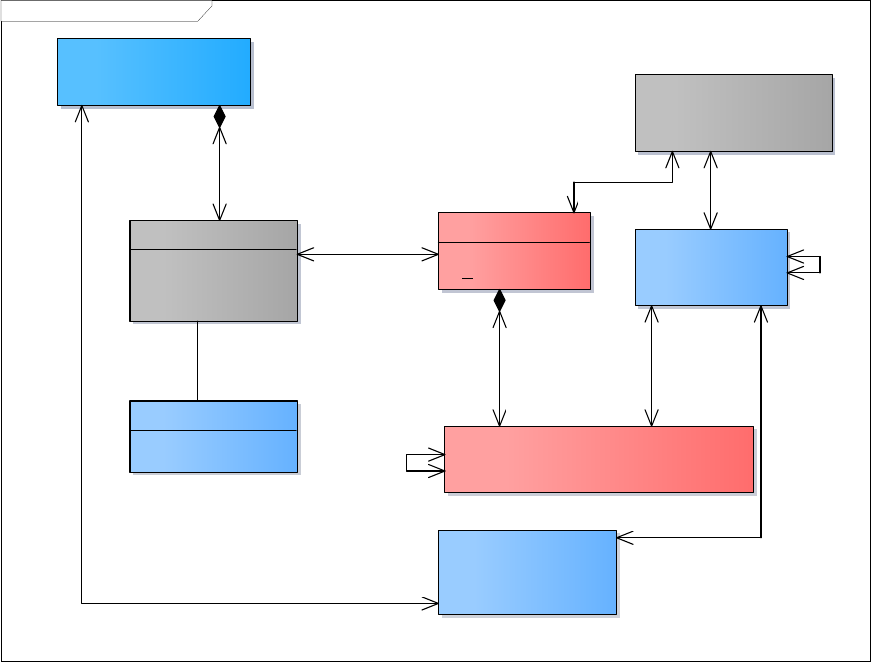
prEN 12896-1:2015 (E)
35
class TM CC Generic Entity MODEL
ENTITY
+ Changed
+ Created
«UID»
+ Id
CLASS IN REPOSITORY
«UID»
+ Id
CC Generic Version Frame MODEL::CLASS IN FRAME
CC Generic Version Frame
MODEL::TYPE OF FRAME
CC Generic Version Frame MODEL:
:TYPE OF VALIDITY
Name: TM CC Generic Entity MODEL
Author: Transmodel
Version: 1.0
Created: 05/02/2014 11:24:00
Updated: 21/05/2014 18:53:00
TYPE OF ENTITY
«UID»
+ Id
CC Generic Version Frame
MODEL::VERSION FRAME
CC Generic Responsibility
MODEL::DATA SOURCE
+validating1
+validated by
*
+instance of
*
+filled by
1
+a classification for
1..*
+classified as 1..*
+characterising
1
+characterised by
*
+including
0..1
+included
in *
+object of 0..1
+dealing with
*
+a classification for
1
+classified as
*
+comprising
1
+belonging to *
+parent of
0..1
+derived from *
+defining *
+defined by *
+comprising
1
+belonging to
*
Figure 10 — Generic Entity – Conceptual Model
5.2.4 Generic Version
The modelling of versions in Transmodel is in effect a version description model, not a model of a version
management system. However, it is allows for fine grained versioning, and uses a uniform and generic
approach that can be used for any time of complex data object. This versioning mechanism is available on all
Transmodel elements, but not mandatory, thus allowing legacy systems without any versioning mechanism to
use Transmodel simply by omitting the versioning attributes. In practice versioning will be often just done at an
aggregate level and not that of the individual data instance.
Public transport data are in a permanent process of evolution; schedule and operational data typically undergo
a regular cycle of planning, distribution and execution, whilst reference data describing the network, such as
stop and line data, will change if the network or physical environment is modified. It is therefore necessary to
be able to organize data elements to support such a lifecycle, with multiple versions of a given element being
in use concurrently, and different assemblies of data referencing different versions for different purposes. This
is achieved in Transmodel with VERSIONs and VERSION FRAMEs.
5.2.4.1 Generic VERSION – Conceptual Model
Each state of an object, or a set of objects, is called a VERSION. VERSIONs of an object may be consecutive
or competitive. Consecutive VERSIONs describe the successive states of an object, whilst competitive
VERSIONs describe an alternative version to use in particular circumstances, i.e. under specific VALIDITY
CONDITIONs (cf. Generic VALIDITY – Conceptual Model below). For example, there may be for a single line
at the same time competitive versions of the line; a simulated line (for planning work or for study), and the
operational line for particular operating periods.

prEN 12896-1:2015 (E)
36
The VERSION describes the identifier and purpose of a version state. The actual version state of the objects
is described by an instance of ENTITY IN VERSION. Thus in a given repository or documents there will be a
single instance of each Transmodel ENTITY and one or multiple instances of ENTITY IN VERSIONs for that
ENTITY; these will be tried together by a common identifier and differentiated by distinct VERSION identifiers.
For example an instance of the entity SCHEMATIC MAP may have multiple SCEMATIC MAP IN VERSION
instances, etc.
The purpose of the VERSION may be categorized with an arbitrary classification using a TYPE OF VERSION,
for example planning, scheduled, operational, etc.
class TM CC Generic Version MODEL
ENTITY IN VERSION
+ Modification [0..1]
«UID»
+ Id
VERSION
+ Description [0..1]
+ EndDate [0..1]
+ Name [0..1]
+ StartDate [0..1]
+ Status [0..1]
«UID»
+ Id
CC Generic Entity
MODEL::ENTITY
CC Generic
Responsibility
MODEL::DATA
SOURCE
Name: TM CC Generic Version MODEL
Author: Transmodel
Version: 1.0
Created: 05/02/2014 11:24:00
Updated: 29/08/2014 14:04:20
TYPE OF VERSION
«UID»
+ Id
+classification for
0..1
+classified as
*
+valid instance of
*
+valid
for
1
+governing
1
+governed by
1..*
+comprising
1
+belonging to
*
+parent of
0..1
+deriving
from *
+parent of
0..1
+deriving from *
+base version for
0..1
+compatible with
0..*
Figure 11 — Generic Version – Conceptual Model
5.2.5 Generic Version Frame
5.2.5.1 Generic VERSION FRAME – Conceptual Model
VERSION FRAMEs allow data to be managed and exchanged as a coherent version, that is a set of instances
(ENTITies IN VERSION) of different entity types that are consistent and correct as to referential integrity and
other business semantics and so are suitable for use without extensive consistency checking, for example, by
an importing application. A VERSION FRAME contains a list of specific versions of an entity, that is, instances
of ENTITY IN VERSION.
The possibilities for including specific types of ENTITies in VERSION in a FRAME are limited by the generic
rules set by a corresponding CLASS IN FRAME. All the classes that are allowed to be present in the frame
are defined by the CLASS IN FRAME, and each frame is defined by its TYPE OF FRAME. VERSION
FRAMEs may have common properties as regards validity. This is described by the TYPE OF FRAME entity
(e.g. vehicle schedules, network description for line versions, etc.). The main property of a TYPE OF FRAME
is the purpose it is designed for.
Thus a particular VERSION FRAME, defined according to a TYPE OF FRAME, is usually limited by
operational parameters: For example VERSION FRAME for network description of “area West” or for fare
versions on “tramway lines”, etc. When these limiting parameters are actual instances data, this may be
described by instances of the VALIDITY CONDITION (cf. Validity Condition Conceptual Model below), related
to the VERSION FRAME. For instance, a VALIDITY CONDITION may represent a TOPOGRAPHIC ZONE
(”area West”) or a VEHICLE MODE (“tramway”).

prEN 12896-1:2015 (E)
37
A TYPE OF FRAME thus may be associated with a particular TYPE OF VALIDITY, which expresses a general
validity environment. The TYPE OF VALIDITY will apply to any VERSION FRAMEs of that type. For instance,
if the schedules designed for day types are to be distinguished from schedules planned for a particular
operating day, different TYPEs OF VALIDITY, which will serve as a basis to select general validity rules, may
specify this difference. Similarly, certain VERSION FRAMEs may be designed only for simulation purposes
and be distinguished from production data, this classification being expressed with a different TYPE OF
VALIDITY.
A TYPE OF FRAME may include other TYPEs OF FRAME, for which the validity rules and processes may be
different. This is represented by a circular relationship on TYPE OF FRAME.
class TM CC Generic Version Frame MODEL
TYPE OF VALIDITY
«UID»
+ Id
CLASS IN FRAME
«UID»
+ Id
TYPE OF FRAME
+ Periodicity [0..1]
+ Nature [0..1]
+ ModificationSet [0..1]
+ Versioning [0..1]
«UID»
+ Id
Name: TM CC Generic Version Frame MODEL
Author: Transmodel
Version: 1.0
Created: 05/02/2014 11:24:00
Updated: 29/08/2014 14:14:41
CC Generic Entity
MODEL::ENTITY
VERSION FRAME
+ Name [0..1]
+ Description [0..1]
«UID»
+ Id
CC Generic Version MODEL:
:VERSION
CC Generic Version
MODEL::ENTITY IN
VERSION
CC Generic Entity
MODEL::CLASS IN
REPOSITORY
CC Generic Validity MODEL::
VALIDITY CONDITION
+parent of 0..1
+derived from *
+validating 1
+validated by *
+part of 0..*
+including 0..*
+base version for
0..1
+compatible with
0..*
+restricting
0..1
+restricted by
*
+comprising
0..*
+belonging to
0..*
+defining *
+defined by *
+a classification
for
1
+classified as
*
+parent of 0..1
+deriving from *
+parent of 0..1
+deriving
from *
+characterising
1
+characterised by
*
+representing
0..1
+represented by 1
+defined
for
0..*
+characterised
by
1
+characterised
by
0..1
+defined
for
*
+governing
1
+governed by
1..*
+comprising
1
+belonging to
*
+including
0..1
+included
in *
+comprising
1
+belonging to
*
+restricted to
1
+defined
for
*
+instance of
*
+filled by
1
+valid instance of
*
+valid for
1
Figure 12 — Generic Version Frame – Conceptual Model
The VERSION FRAME itself is versioned, so that if any change is made to the contents of a frame to add,
change or delete its entities, then a new version of the frame must be created..
For a defined group of object instances, there may be several (consecutive or competitive) VERSIONs of a
VERSION FRAME. For example, the contents of a frame containing the stop points for a town will change as
they are added, updated or deleted, so there will be successive versions of the same frame, or there may be
prEN 12896-1:2015 (E)
38
successive instances of a given VERSION FRAME for timetables reflecting successive changes to a given
schedule. In summary:
A given aggregation may undergo successive versions as the data evolves through its lifecycle, so
there may be several consecutive VERSIONs of a VERSION FRAME.
A given aggregation may represent an alternative to be used in particular conditions ,so there may be
several competitive VERSIONs of a VERSION FRAME in which case a VALIDITY CONDITION must
be attached to the frame to discriminate the conditions for use.
5.2.6 Generic Validity
5.2.6.1 Generic VALIDITY – Conceptual Model
An ENTITY, a VERSION or a VERSION FRAME may be associated with VALIDITY CONDITION, detailing
under which conditions expressed e.g. by space- or time-related parameters a version is active or available.
Each VALIDITY CONDITION can consist of:
a parameter (e.g. a start date);
a type of application of this parameter (“for”, “from”, “until”, etc.).
A VALIDITY CONDITION parameter may be:
a time-related parameter, which will be in general an instance of an ENTITY: OPERATING DAY, ,
PROPERTY OF DAY, DAY TYPE, TIME BAND, etc.;
a VALIDITY TRIGGER (road works, rainy weather, until further advice, etc.), which will be activated
thanks to a mechanism, an external output or a manual entry;
Any other VALIDITY RULE PARAMETER.

prEN 12896-1:2015 (E)
39
class TM CC Generic Validity MODEL
VALIDITY CONDITION
+ Description [0..1]
+ Name [0..1]
«UID»
+ Id
VALIDITY RULE PARAMETER
+ AttributeName [0..1]
+ AttributeValue [0..1]
+ ComparisonOperator [0..1]
+ IsValid [0..1]
+ Method [0..1]
«UID»
+ Id
VALIDITY TRIGGER
+ PrivateCode [0..1]
«UID»
+ Id
CC Generic Version
MODEL::VERSION
CC Generic Entity MODEL::
ENTITY
Name: TM CC Generic Validity MODEL
Author: Transmodel
Version: 1.0
Created: 05/02/2014 11:24:00
Updated: 29/08/2014 14:17:12
CC Generic
Version Frame
MODEL::VERSION
FRAME
{exclusion}
+comprising
1
+belonging to
*
+defining 1
+defined by
*
+defined for
0..*
+characterised by
1
+representing
0..1
+represented by
1
+characterised
by
0..1
+defined for
*
+restricted to 1
+defined for
*
+defining 1
+defined by
*
+parent of
0..1
+deriving
from *
+part of
0..*
+including
0..*
+providing value for
0..1
+using value of
0..*
+defining
1
+defined by *
Figure 13— Generic Validity Model
5.2.7 Generic Delta Model
A data linked to a VERSION may be deriving (possibly with some modifications) from another. It may be of
interest to record this inheritance, in particular when there are successive states of a data in different
VERSIONs and that it is of interest to record the modifications. This is described by a circular relationship on
ENTITY IN VERSION.
In a more detailed way, it may be of interest to record the values that are modified. This is described by the
entity DELTA, which stores the changes in values of one or several attributes, from a VERSION to another.
This applies either when the same ENTITY may be present in several VERSIONs, or when different ENTITies
are deriving from each other (circular relationship described above) between different VERSIONs.
However, the data stored within a VERSION is not necessarily frozen and may be allowed to evolve
(according to the TYPE OF VALIDITY). This is of course in particular the case where only one implicit
VERSION exists. In such a situation, it may be of interest to record TRACEs of changes operated on an
ENTITY within the same VERSION (date of modification, user, changed value, etc.).

prEN 12896-1:2015 (E)
40
class TM CC Generic Delta MODEL
CC Generic Version MODEL::ENTITY IN
VERSION
TRACE
+ ChangedAt
+ ChangedBy [0..1]
+ Description [0..1]
«UID»
+ Id
DELTA
+ DeltaValue
«UID»
+ Id
Name: TM CC Generic Delta MODEL
Author: Transmodel
Version: 1.0
Created: 05/02/2014 11:24:00
Updated: 29/08/2014 14:18:40
+document within *
+changed by 1
+previous value of
1
+from version
*
+parent of 0..1
+deriving from *
+updated value
1
+to version
*
Figure 14 — Generic Delta Model
5.3 Responsibility
5.3.1 Introduction
Transmodel data will be used in different environments that can have a complex organisational structure. For
instance, information is planned, revised, forwarded, enriched, combined with other plans and forwarded
again to the final user at some time. This process often involves several organisations or departments that
each add, change or remove information in a complex workflow. These participating organisations can be
strictly PT concerns, or can be external, such as governmental departments or other management agents.
Which organisations are involved, what roles they have and what responsibility they execute cannot be
determined beforehand for all possible environments in which Transmodel will be used. Even the structure
and implementation of the processes for information planning, collecting and forwarding depend on various
factors that cannot be determined beforehand. Hence, Transmodel has a generic organisational and
responsibility model that can be applied in a variety of different environments and workflows and be used for a
variety of purposes. The model in effect defines metadata as to the ownership of data that can be used to help
manage the data.
The use of the responsibility model in a specific situation or environment is optional.
The responsibility model makes it possible:
To define operational responsibility for the real-life entities that are described by the information. For
example, in processes for a stop information model it can specify which organisation is responsible
for planning and maintenance of the physical stop.
To define data management related responsibilities for the information itself. e.g. functional or
technical IT data management regarding a set of produced, collected or forwarded plan information.
This can be used to identify who needs to be contacted to correct or amend data.
To exchange partial information falling under a certain responsibility set.
If used, the responsibility model can be applied to achieve the following goals:
Provide as part of the passenger information the contact information of agencies or help-desks to
turn to in case of reservations, questions, complaints, etc.
prEN 12896-1:2015 (E)
41
Provide IT and PT related responsibility information for the purpose of management, assessment,
etc. activities concerning Quality Management and Quality Control.
Associate Intellectual Property Rights with individual data elements or groups of elements.
Allow delegation of data management: a receiving system can check the authorizations in relation to
responsibility for provided data and see if the provider is authenticated to manage that data. This
concept can be used to protect data in VERSION FRAMEs from being changed by the wrong parties.
5.3.2 Responsibility – Model overview
The Responsibility Model is referenced by all other parts. There are three sub models. They extend the basic
Entity & Versioning models:
The core RESPONSIBILITY model describes basic concepts related to the responsibility description
over data;
The RESPONSIBILITY ROLE model describes the roles different organisations may take;
The ORGANISATION model defines the common structures of an organisation. Note that this is
further extended in the Reusable Components model (see later) with specific classes for specific
types of organisation such as OPERATOR, AUTHORITY, SERVICED ORGANISATION, etc.
The Responsibility Model extends the basic Entity & Versioning models to create the fundamental framework
classes from which all the useful Transmodel models are built.
5.3.3 Generic Responsibility
5.3.3.1 Generic RESPONSIBILITY – Conceptual Model
A certain aspect, or set of aspects, of responsibility in relation to an ENTITY is specified by associating a
RESPONSIBILITY SET with the ENTITY. Each RESPONSIBILITY SET can contain one or more
RESPONSIBILITY ROLE ASSIGNMENTs that allocate different types of RESPONSIBILITY ROLE to an
ORGANISATION or a specific ORGANISATION PART.
RESPONSIBILITY SETs may be used at different levels of aggregation. It is possible to specify a different set
for each different ENTITY (or rather ENTITY IN VERSION), or just at the Frame Level. The RESPONSIBILITY
SET for an ENTITY may change in successive ENTITY IN VERSIONs
The RESPONSIBILITY ROLE describes the kind of responsibility that is enacted; the RESPONSIBILITY
ROLE ASSIGNMENT assigns the responsibility to the RESPONSIBILITY SET.
The ADMINISTRATIVE ZONE and RESPONSIBILITY ROLE ASSIGNMENT are used to describe the specific
situation of the delegation of the regional responsibility of an authority to an organisation. This can be e.g. the
delegation using a concession for the operation of a PT service or the delegation of a regional travel
information provision service.

prEN 12896-1:2015 (E)
42
class TM CC Responsibility MODEL
CC Generic Entity
MODEL::ENTITY
CC Responsibility Role MODEL::RESPONSIBILITY ROLE ASSIGNMENT
CC Generic Organisation MODEL::
ORGANISATION
CC Generic Version MODEL::ENTITY IN
VERSION
CC Generic Organisation MODEL::
ORGANISATION PART
ZONE
CC Generic Organisation
MODEL::ADMINISTRATIVE
ZONE
CC Responsibility Role
MODEL::RESPONSIBILITY SET
DATA SOURCE
+ Email [0..1]
«UID»
+ Id
Name: TM CC Responsibility MODEL
Author: Transmodel
Version: 1.0
Created: 05/02/2014 11:24:00
Updated: 21/05/2014 19:02:53
+in charge of
0..1
+delegated to
0..*
+assigned to
0..*
+in charge of
1
+managed by
0..*
+managing 1
+valid instance of
*
+valid for
1
+delegating
0..*
+delegated
to
0..*
+comprising
1
+belonging to
*
+referring to
0..*
administrating
1..
+in charge of 0..1
+delegated to
0..*
+under the responsibility of
1..*
+responsible for
0..*
+parent of
0..1
+deriving from *
+part of
0..*
+made up of
1
+for *
+concerned
by
*
+composed of
1+part of
1..*
+managed by
0..*
+managing 1
Figure 15 — Responsibility – Conceptual Model
5.3.3.2 Example of RESPONSIBILITY SETs
For example, in the UK, the NPTG (Nation Public Transport Gazetteer) corresponds to a centrally managed
set of RESPONSIBILITY SETs managed by the Department for Transport that describe how coordinate the
management of stop data.
For managing most types of stop data (i.e. for bus stops, airports, ferry stops etc) the country is
divided into regions and areas within regions. This can be indicated by a RESPONSIBILITY SET for
each area; each set is associated with an ADMINISTRATIVE ZONE that designates the area’s
boundaries and is used to associate the codespace and prefix to use for stop identifiers from that
region. Within a designated area, all stop data other than rail station and certain other location data is
collected and maintained by the ORGANISATION indicated by the RESPONSIBILITY SET (usually
an AUTHORITY). In this case the ADMINISTRATIVE ZONEs do not overlap.
Certain types of stop data, for example for rail stations, are maintained centrally for the whole
country. There is a RESPONSIBILITY SET for each type of data that associates it with the
appropriate organisation and zone. The ADMINISTRATIVE ZONEs overlap the zones for other types
of stop data.
A single RESPONSIBILITY SET defines the Department for Transport’s central responsibility for
creating all the other RESPONSIBILITY SETs. Another RESPONSIBILITY SET defines the
responsibility of a contracting organisation to aggregate and distribute the data.
prEN 12896-1:2015 (E)
43
5.3.4 Responsibility Role
5.3.4.1 RESPONSIBILITY ROLE – Conceptual Model
The RESPONSIBILITY ROLE model describes the specific properties of a RESPONSIBILITY SET as a set of
assignments of specific roles to specific ORGANISATIONs or ORGANISATION PARTs.
Each RESPONSIBILITY ROLE ASSIGNMENT allocates a specific role to a specified ORGANISATION or
ORGANISATION PART.
A full information delivery chain for Travel Information could involve multiple actors. This model will allow
identifying the different roles actor can have in such a multi-organisation process.
As different aspects of public transport could be handled by different organisation parts, and sometimes are
subcontracted to third parties, it is often useful to describe who is responsible for a specific role, within the
delivered data.
Examples of roles are:
Data Origination
Data Augmentation
Data Aggregation
Data Distribution
Planning
Operation
Control Centre (directive pt-management centre)
Monitor Centre (only receiving and collecting data)
Data IPR Ownership
Entity Legal Ownership
Scheduler,
StopPointManager,
RoadManager,
RoadDisplayManager,
SubContractor,
TravelInformationServiceProvider,
Other

prEN 12896-1:2015 (E)
44
class TM CC Responsibility Role MODEL
CC Generic Entity
MODEL::ENTITY
RESPONSIBILITY ROLE
ASSIGNMENT
«UID»
+ Id
RESPONSIBILITY ROLE
«UID»
+ Id
CC Generic
Organisation MODEL:
:ORGANISATION
CC Generic
Version MODEL::
ENTITY IN VERSION
CC Generic
Organisation
MODEL::
ORGANISATION
PART
Data Management Role
Data Origination
Data Augmentation
Data Aggregation
Data Distribution
Data Ownership
Other
Stakeholder Role
Planning
Operation
Control
Data IPR Ownership
Entity Legal Ownership
Other
RESPONSIBILITY SET
«UID»
+ Id
TYPE OF RESPONSIBILITY ROLE
«UID»
+ Id
Name: TM CC Responsibility Role MODEL
Author: Transmodel
Version: 1.0
Created: 05/02/2014 11:24:00
Updated: 29/08/2014 14:49:31
Data Management Role
Stakeholder Role
+for*
+concerned by
*
+composed of
1
+part of
1..*
+part of
0..*
+made up of 1
+causing
1
+caused by
0..*
+a classification for
0..1
+classified as
0..*
+under the responsibility of
1..*
+responsible for 0..*
+managed by
0..*
+managing
1
+assigned to
0..*
+in charge of
1
+in charge of
0..1
+delegated to
0..*
+delegating
0..*
+delegated to 0..*
+parent of
0..1
+deriving from *
+valid instance of
*
+valid for
1
Figure 16 — Responsibility Role – Conceptual Model
5.3.5 Generic Organisation
The Generic ORGANISATION Model defines abstract ORGANISATION elements that can be used wherever
there is a need to describe an organisation. It is extended in the Reusable Components section with
AUTHORITY, OPERATOR and other concrete organisation definitions specifically relevant for the transport
domain.
5.3.5.1 Generic ORGANISATION – Conceptual Model
The entity ORGANISATION represents an organisation that is involved in the planning, collecting or provision
of PT information. For example, a company providing a public transport information service, an authority, an
operator, or a company providing an information collection service.
Many organisations break down their operations in different organisation parts. This may be important not only
from the operational point of view, but also for data administration, as such units may have different
responsibilities. Some common data will be shared between them whereas some other data will be managed
by a specific part. The RESPONSIBILITY ROLE ASSIGNMENT can be used to describe these
responsibilities.

prEN 12896-1:2015 (E)
45
An ORGANISATION can consist of several DEPARTMENTs or ORGANISATIONAL UNITs. Those
departments or units are modelled in the ORGANISATION PART.
A DEPARTMENT can consist of one or more ORGANISATIONAL UNITs, which are in charge of operational
functions. In a PTO context, a DEPARTMENT could comprise all ORGANISATIONAL UNITs responsible for
the lines served by the same transport mode, or using the same type of operation (e.g. regular service, night
service).
In some cases, the organisational aspect of responsibilities for planning and operation need not necessarily
be present in a company data model. Therefore, the relationships to (and the existence of) these
organisational entities are optional.
The ADMINISTRATIVE ZONE represents a set of PT objects related to a district, a region, a city, a
municipality, a traffic system, a set of lines or other subdivision for a specific purpose.
class TM CC Generic Organisation MODEL
ORGANISATION
+ Description [0..1]
+ LegalName [0..1]
+ Name
+ Remarks [0..1]
+ ShortName [0..1]
+ TradingName [0..1]
+ Status [0..1]
+ ValidFromDate [0..1]
+ ValidToDate [0..1]
«UID»
+ Id
ORGANISATION PART
+ Name [0..1]
+ ShortName [0..1]
+ Description [0..1]
«UID»
+ Id
Name: TM CC Generic Organisation MODEL
Author: Transmodel
Version: 1.0
Created: 05/02/2014 11:24:00
Updated: 29/08/2014 14:59:00
ORGANISATIONAL UNIT
«UID»
+ Id
DEPARTMENT
+ Name
«UID»
+ Id
ZONE
ADMINISTRATIVE ZONE
+ ShortName [0..1]
«UID»
+ id
CC Responsibility Role
MODEL::RESPONSIBILITY
ROLE ASSIGNMENT
TYPE OF ORGANISATION
«UID»
+ Id
TYPE OF OPERATION
«UID»
+ Id
CONTACT DETAILS
+ ContactPerson [0..1]
+ Email [0..1]
+ Fax [0..1]
+ FurtherDetails [0..1]
+ Phone [0..1]
+ Url [0..1]
«UID»
+ Id
+a classification for 0..1
+classified as 0..*
+managed
by
0..*
+managing
1
+in charge of
0..1
+delegated to 0..*
+in charge of
0..1
+delegated to
0..*
+part of
1..*
+comprising
1
+classified as
0..*
+a classification for
0..1
+for
0..*
+characterised by
1
+assigned to
0..*
+in charge of
1
+part of
0..*
+made up of
1
Figure 17 — Generic Organisation — Conceptual Model
5.4 Explicit Frames
The Generic Version Frame Conceptual Model above provides a tool to specify the contents of a given frame
using the CLASS IN FRAME mechanism which in effect provides metadata that a system following the
Transmodel specification can use to check that all of the necessary elements are present to built a coherent
set of versioned data.
prEN 12896-1:2015 (E)
46
This general frame mechanism is complemented by a more specific set of “Explicit“ VERSION FRAMES that
specify sets of data elements appropriate for a particular use case or set of related use cases; for example,
INFRASTRUCTURE FRAME, SITE FRAME, TIMETABLE FRAME, etc. Each of these represents a
predefined combination of data types that are commonly managed and/or exchanged together as part of the
data management processes.
Sometimes data elements from more than one type of an explicit frame are needed: a COMPOSITE FRAME
can be used to group a coherent set of explicit frames.
The explicit frames correspond to various parts of Transmodel and in most cases are described in the
appropriate section along with their contents. In most cases a given Transmodel element appears only in one
explicit frame. A summary of the identified frames is given below.
There are in addition two types of explicit VERSION FRAMEs that have a general purpose and so are
described here as part of the framework.
COMPOSITE FRAME – A container used to group other frames that meet the same validity conditions.
GENERAL FRAME – A general purpose frame that can contain an arbitrary group of ENTITies.
RESOURCE FRAME – A container to group generic resource data considered as being useful for all
functional domains e.g. referring to responsibilities, organisations, vehicle types, etc
5.4.1 Composite Frame
5.4.1.1 COMPOSITE FRAME – Conceptual Model
The COMPOSITE FRAME is used to group other frames that have the same VALIDITY CONDITIONs.
A COMPOSITE FRAME may contain another COMPOSITE FRAME.

prEN 12896-1:2015 (E)
47
class TM CC Composite Frame MODEL
CC Generic Version Frame MODEL::VERSION FRAME
Fare Frame
MODEL::FARE
FRAME
CC Generic Validity MODEL:
:VALIDITY CONDITION
Name: TM CC Composite Frame MODEL
Author: Transmodel
Version: 1.0
Created: 04/03/2014 17:44:08
Updated: 29/08/2014 15:00:32
COMPOSITE FRAME
CC Resource
Frame MODEL::
RESOURCE
FRAME
CC Service Calendar
Frame MODEL::
SERVICE CALENDAR
FRAME
Infrastructure Frame
MODEL::
INFRASTRUCTURE
FRAME
Site Frame
MODEL::SITE
FRAME
Service Frame
MODEL::SERVICE
FRAME
Diver Schedule
FRAME::DRIVER
SCHEDULE FRAME
Vehicle Schedule
Frame MODEL::
VEHICLE SCHEDULE
FRAME
Timetable Frame
MODEL::
TIMETABLE
FRAME
+part of 0..*
+including 0..*
+comprising
0..1
+valid for 0..*
+restricted to
1
+defined for
*
+dated by
0..*
+take use of 0..1
+containing
0..1
+part of
0..*
Figure 18 — Composite Frame – Conceptual Model
5.4.2 General Frame
5.4.2.1 GENERAL FRAME – Conceptual Model
The GENERAL FRAME is for general purpose use and may contain any type of Transmodel object.

prEN 12896-1:2015 (E)
48
class TM CC General Frame MODEL
CC Generic Version MODEL::
ENTITY IN VERSION
GENERAL FRAME
«UID»
+ Id
CC Generic Version Frame
MODEL::VERSION FRAME
CC Generic Validity
MODEL::VALIDITY
CONDITION
Name: TM CC General Frame MODEL
Author: Transmodel
Version: 1.0
Created: 04/03/2014 18:55:42
Updated: 29/08/2014 15:01:22
CC Generic Responsibility
MODEL::DATA SOURCE
+part of 0..*
+including
0..*
+comprising
0..*
+belonging to
0..*
+parent of 0..1
+deriving from *
+object of 0..1
+dealing with
*
+restricted to
1
+defined for
*
Figure 19 — General Frame – Conceptual Model
5.4.3 Resource Frame
5.4.3.1 RESOURCE FRAME – Conceptual Model
A RESOURCE FRAME contains general purpose components such as ORGANISATIONs, VEHICLE TYPEs,
etc. described in further sections of this document.
The diagram below presents the main elements of the RESOURCE FRAME which may comprise also other
elements of use for the different functional domains.

prEN 12896-1:2015 (E)
49
class TM CC Resource Frame MODEL
Name: TM CC Resource Frame MODEL
Author: Transmodel
Version: 1.0
Created: 07/03/2014 17:58:40
Updated: 29/08/2014 15:02:23
CC Generic
Version Frame
MODEL::
VERSION FRAME
CC Generic
Version Frame
MODEL::TYPE OF
FRAME
CC Generic
Version MODEL::
TYPE OF
VERSION
CC Generic Point &
Link MODEL::TYPE
OF POINT
CC Generic Point &
Link MODEL::TYPE
OF LINK
CC Generic
Validity MODEL::
VALIDITY
CONDITION
CC Generic Point
& Link Sequence
MODEL::TYPE OF
LINK SEQUENCE
CC Generic Zone
and Feature
MODEL::TYPE OF
ZONE
CC Generic
Projection MODEL:
:TYPE OF
PROJECTION
CC Vehicle Type
MODEL::PURPOSE
OF EQUIPMENT
PROFILE
RESOURCE FRAME
«UID»
+ Id
CC Generic
Grouping MODEL::
PURPOSE OF
GROUPING
CC Transport
Mode MODEL::
MODE
CC Responsibility
Role MODEL::
RESPONSIBILITY SET
CC Transport
Organisations
MODEL::GROUP
OF OPERATORS
CC Transport
Organisations
MODEL::
OPERATOR
CC Transport
Organisations
MODEL::
AUTHORITY
CC Generic
Organisation
MODEL::
ORGANISATION
CC Additional
Organisation MODEL::
TRAVEL AGENT
CC Additional
Organisation
MODEL::OTHER
ORGANISATION
CC Additional
Organisation MODEL::
MANAGEMENT AGENT
CC Additional
Organisation MODEL::
SERVICED
ORGANISATION
CC Generic
Organisation
MODEL::
ORGANISATION
PART
CC Generic
Organisation MODEL::
ORGANISATIONAL
UNIT
CC Generic
Organisation MODEL::
DEPARTMENT
CC Transport
Organisations MODEL::
OPERATIONAL
CONTEXT
CC Transport
Organisations
MODEL::CONTROL
CENTRE
CC Vehicle Type
MODEL::VEHICLE
CC Vehicle Type
MODEL::VEHICLE
EQUIPMENT
PROFILE
CC Vehicle Type
MODEL::VEHICLE
MODEL
CC Vehicle Type
MODEL::VEHICLE
TYPE
CC Generic
Equipment MODEL::
EQUIPMENT
CC Schematic
Map MODEL::
SCHEMATIC MAP
CC Generic
Responsibility
MODEL::DATA
SOURCE
CC Generic
Grouping MODEL::
GROUP OF ENTITIES
*
0..1
*
0..1
*
0..1
*
0..1
*
0..1
*
0..1
+in 1..*
+equipped with
1
*
0..1
*
0..1
+a classification
for
1 +classified as
*
*
0..1
*
0..1
*
0..1
*
0..1
*
0..1
+determined by
0..*
+determining
+part of 0..*
+including 0..*
*
0..1
+object of
0..1
+dealing with
*
+part of 0..*
+made up of
1
+classifying
0..1
+classified as
*
*
0..1
+a classification
for
1
+classified as
*
*
0..1
*
0..1
+characterising
1
+characterised by
*
*
0..1
*
0..1
+part of
1..*
+comprising
1
*
0..1
*
0..1
*
0..1
+grouping
*
+grouped in
1..*
+restricted to
1
+defined for
*
Figure 20 — Resource Frame – Overview
5.4.4 Service Calendar Frame
5.4.4.1 SERVICE CALENDAR FRAME– Conceptual Model
In further sections data characterising time-related information will be described. The set of data containing
service calendar information, to which the same VALIDITY CONDITIONs have been assigned is an explicit
frame called SERVICE CALENDAR FRAME.

prEN 12896-1:2015 (E)
50
class TM CC Service Calendar Frame MODEL
CC Service
Calendar MODEL::
DAY TYPE
CC Service
Calendar MODEL:
:OPERATING DAY
CC Service
Calendar MODEL:
:OPERATING
PERIOD
CC Service
Calendar MODEL::
SERVICE
CALENDAR
CC Service
Calendar MODEL::
DAY TYPE
ASSIGNMENT
CC Service
Calendar MODEL:
:TIME BAND
SERVICE CALENDAR FRAME
«UID»
+ Id
Name: TM CC Service Calendar Frame MODEL
Author: Transmodel
Version: 1.0
Created: 07/03/2014 21:17:53
Updated: 29/08/2014 15:02:56
CC Generic Version
Frame MODEL::VERSION
FRAME
CC Generic
Validity MODEL::
VALIDITY
CONDITION
*
0..1
+within
1
+ for
0..*
+defined by 1
+for the definition of
0..*
+specifying
*
+specified by
1
*
0..1
*
0..1
+restricted to
1
+defined for
*
*
0..1
+part of 0..* +including 0..*
+the start day of
1
+starting at
0..*
+used to define 0..*
+for 0..*
+the end of
1
+ending at 0..*
+used to
define
1
+for
*
Figure 21 — Service Calendar Frame – Conceptual Model
5.4.5 Other Explicit Frames
The detailed structure of the following explicit frames will be given in the corresponding parts of the Public
Transport Reference Data Model.
Space- related concepts:
INFRASTRUCTURE FRAME: grouping of data describing the infrastructure network and the restrictions
related to it.
SITE FRAME: grouping sites, stop places, points of interest and other fixed objects.
SERVICE FRAME: network topology description elements such as lines, routes, scheduled stop points,
work patterns for vehicles, etc.
Time- related concepts:
TIMETABLE FRAME: timetable elements and journeys with timings.
VEHICLE SCHEDULE FRAME: vehicle schedules and their components.

prEN 12896-1:2015 (E)
51
Fare related concepts:
FARE FRAME: tariffs, access rights, fare products, etc
5.5 Generic Framework Model
The Generic Framework model defines common framework objects and relationships that are used as a basis
for defining the elements of the Transmodel functional models. The framework defines common abstract
supertypes that can be specialized to create the concrete elements of the Transmodel modules.
5.5.1 Generic Framework – Model overview
The Framework Models extend the core Transmodel models for responsibility, versioning etc. so that all
framework elements can be versioned and managed.
The LOCATION Model defines location related elements such as coordinates.
The GROUPING model provides a means of grouping elements.
The POINT & LINK model provides a model for defining one-dimensional points and two-dimensional
links.
The LINK SEQUENCE model provides a means of defining graphs of points and links such as are
commonly found in layered PT models.
The ZONE model provides a model for defining two-dimensional zones (with possible one-
dimensional point centroid).
The PROJECTION model provides a means of defining mappings between different graphs of
POINTs and LINKs.
The PLACE model provides a model for defining named places and links between them.
5.5.2 Location Model
5.5.2.1 LOCATION – Conceptual Model
The Location provides a representation of the basic coordinates of those entities that are located in space, for
example, POINTs and LINKs and ZONEs.
Transmodel uses a subset of the Open Geospatial Consortium’s Geographic Mark-up Language (OGC
GML)() schema to define coordinates. This allows different spatial reference systems (SRS) to be used to
express the geographic location of objects of different shape (point, linestring, polygon, and multi-points if
using the OGC normalized wording at http://www.opengeospatial.org/standards,). The spatial reference
defines an ellipsoid, a datum using that ellipsoid, and either a geocentric, geographic or projection coordinate
system. The projection also always has a geographic coordinate system associated with it.
Some of the commonly used spatial reference systems are: 4326 - WGS 84 Long Lat, 4269 - NAD 83 Long
Lat, and 3395 - WGS 84 World Mercator, but several hundred are available depending on the country,
required precision, purpose of the location, etc. See http://spatialreference.org/ for more details.

prEN 12896-1:2015 (E)
52
The location of a POINT is dependent on the LOCATING SYSTEM used. Given a LOCATING SYSTEM,
every POINT may be located in this system by a LOCATION. One of the classical ways to locate a POINT is
to assign coordinates to it. The LOCATION is hence defined by two coordinates in a two-dimensional
representation and possibly by a third coordinate relating the point to a surface. Examples of coordinates are
x- and y-values in a plane graphic or diagram, degree of longitude and latitude on a globe, GPS-coordinates,
the angle to the North and the distance from an origin, etc.
Every LOCATION must be defined according to one and only one LOCATING SYSTEM and must be located
at one and only one POINT. Any POINT may be located by one or more LOCATIONs, each of which may
refer to only one LOCATING SYSTEM. The LOCATING SYSTEM may be specified implicitly by the context
(e.g. on the VERSION FRAME, or on an individual LOCATION).
class TM CC Location MODEL
CC Generic Point &
Link MODEL::POINT
LOCATION
+ Coordinates [0..1]
+ Latitude [0..1]
+ Longitude [0..1]
+ Altitude [0..1]
+ Precision [0..1]
«UID»
+ Id
LOCATING SYSTEM
+ LocatingSystemName
«UID»
+ Id
Name: TM CC Location MODEL
Author: Tranmodel
Version: 1.0
Created: 05/02/2014 11:24:00
Updated: 29/08/2014 15:29:39
+referring to *
+reference for
1
+locating
*
+located by
1
Figure 22 — Location – Conceptual Model
5.5.3 Generic Grouping
5.5.3.1 Introduction
There is often a need in public transport to group objects into a set, for example a group of lines, group of
points, etc. Some kinds of grouping are very frequent; others are specific to a particular local situation.
Transmodel provides an explicit grouping mechanism that can be used for the more commonly found cases,
such as GROUP OF POINTs, and a generic grouping mechanism that can be used to group any kind of
object.
Grouping may be very useful in situations like:
Defining a bus network by grouping a set of LINK SEQUENCEs together,
Defining zones by grouping sets of POINTs,
etc.

prEN 12896-1:2015 (E)
53
5.5.3.2 GROUPING – Conceptual Model
One or more ENTITies of any type may be grouped using a GROUP of ENTITies.
Objects like POINT, LINK, and LINK SEQUENCE may be grouped by the corresponding entities GROUP OF
POINTS, GROUP OF LINKS, and GROUP OF LINK SEQUENCES respectively.
Each of these groups can be classified by a PURPOSE OF GROUPING. Such a group is the association of
specific elements of a given type into a group needed for a particular functional purpose (for example, WIRE
ELEMENTs having a specific power supply type). The PURPOSE OF GROUPING refers to the functional
purpose for which the associated groups of elements are defined.
Some other types of ENTITY also have an inherent grouping semantic. For example, for example STOP
AREA (or also indeed ZONE) incorporates the generic concept of a grouping of POINTs.
The assignment of elements to groups of such elements is represented by many-to-many relationships. An
ENTITY can belong to more than one group, either for the same or a different PURPOSE OF GROUPING.
class TM CC Generic Grouping MODEL
PURPOSE OF GROUPING
«UID»
+ Id
GROUP OF ENTITIES
+ Name [0..1]
+ Description [0..1]
+ ShortName [0..1]
«UID»
+ Id
Name: TM CC Generic Grouping MODEL
Author: Transmodel
Version: 1.0
Created: 05/02/2014 11:24:00
Updated: 21/05/2014 19:17:06
CC Generic Entity
MODEL::TYPE OF ENTITY
CC Generic Entity MODEL::
ENTITY
CC Generic Version MODEL::ENTITY
IN VERSION
CC Generic Entity MODEL::
CLASS IN REPOSITORY
+instance of
*
+filled by
1
+made up of 0..*
+included in
1..*
+classified as
0..*
+a classification for
1
+allowed for
0..*
+restricted to
0..*
+valid instance of
*
+valid
for
1
+a classification
for
1..*
+classified as
1..*
+parent of 0..1
+deriving from *
Figure 23 — Generic Grouping – Conceptual Model
5.5.3.3 Classifying Groups
The PURPOSE OF GROUPING can be used to explain the purpose of arbitrary groupings of elements and to
specify the allowed members.

prEN 12896-1:2015 (E)
54
class TM CC Explicit Grouping Possibilities MODEL
PURPOSE OF GROUPING
«UID»
+ Id
CC Generic Point & Link
Sequence MODEL::GROUP OF
LINK SEQUENCES
CC Generic Point & Link
Sequence MODEL::TYPE OF LINK
SEQUENCE
CC Generic Point & Link
MODEL::GROUP OF LINKS
CC Generic Point & Link
MODEL::TYPE OF LINK
CC Generic Point & Link
MODEL::TYPE OF POINT
CC Generic Point & Link
MODEL::GROUP OF POINTS
Name: TM CC Explicit Grouping Possibilities MODEL
Author: Transmodel
Version: 1.0
Created: 05/02/2014 11:24:00
Updated: 21/05/2014 19:14:11
+classification for 1
+classified as
*
+restricted to *
+allowed for *
+restricted to
*
+allowed for *
+classification for
1
+classified as
*
+classification for
1
+classified as *
+restricted to
*
+allowed for
*
Figure 24 — Explicit Grouping Possibilities – Conceptual Model
5.5.4 Generic Point & Link
5.5.4.1 Generic POINT & LINK – Conceptual Model
One of the most important aspects of information systems dealing with public transport is the representation of
the networks over which the services are operated. Such a representation describes the objects comprising a
network (e.g. stations, lines, etc.) using simplified and conventional topological objects: points, links and for
some purposes, zones. Specific roles are assigned to these simple objects, according to the functional
purpose of the description.
The representation is chosen to be independent of the underlying geospatial context in which the network
resides, but may be projected onto it or other spatial contexts using a projection model – see later.
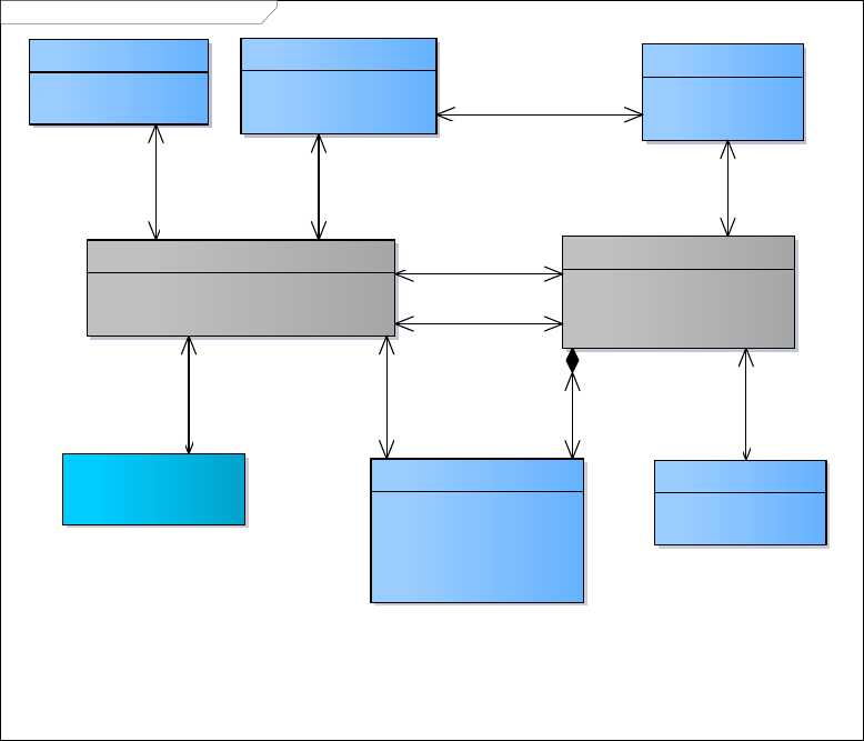
prEN 12896-1:2015 (E)
55
class TM CC Generic Point & Link MODEL
GROUP OF LINKS
«UID»
+ Id
GROUP OF POINTS
«UID»
+ Id
LINK
+ Name [0..1]
+ Distance [0..1]
«UID»
+ Id
POINT
+ Name [0..1]
«UID»
+ Id
POINT ON LINK
+ Name [0..1]
+ Order
+ DistanceFromStart [0..1]
«UID»
+ Id
TYPE OF LINK
+ Name [0..1]
«UID»
+ Id
TYPE OF POINT
+ Name [0..1]
«UID»
+ Id
Name: TM CC Generic Point & Link MODEL
Author: Transmodel
Version: 1.0
Created: 05/02/2014 11:24:00
Updated: 29/08/2014 15:45:00
CC Generic Location MODEL:
:LOCATION
+passing
through
1
+located on
*
+viewed
as
1
+a view
of
*
+a classification
for
1..*
+classified as
*
+limiting
0..1
+between
*
+made up of *
+included in
1..*
+locating *
+located by 1
+start of
1
+from
*
+a classification
for
1..*
+classified as
*
+included
in
1..*
+composed
of
*
+to
*
+end
of
1
Figure 25 — Generic Point & Link – Conceptual Model
5.5.4.2 Points
Topological descriptions of the spatial structure of a public transport network are generally built with points.
Thus, an entity POINT is defined as the most basic entity of the network model. A POINT represents a 0-
dimension node of the network. It marks the location of bus stops, parking places or other types of POINTs.
A TYPE OF POINT is defined as an entity to describe common roles played by a number of POINTs. Each
POINT is functionally classified as being of one or more types, according to the specific information needs of a
particular functional domain.
Certain TYPEs of POINTs are regarded as important enough to be additionally represented by a separate
concept. The most important of these are the SCHEDULED STOP POINT, TIMING POINT and ROUTE
POINT entities, described in a further part of this standard. Other examples are ROAD JUNCTION,
ACTIVATION POINT, etc. The types, if not explicitly defined by an entity of the reference model, may be
specified by the generic entity TYPE OF POINT. Any POINT may be of more than one type. For example, the
same POINT may be a ROUTE POINT, a TIMING POINT and may be an ACTIVATION POINT as well.
5.5.4.3 Links
Between two POINTs of any type, a LINK may be defined to store spatial information (e.g. the distance a
vehicle will cover crossing this link). LINKs represent 1-dimensional connections between POINTs. There
must be no LINKs without one limiting POINT at each end. Two relationships between the POINT and the
LINK entity specify the limiting POINTs of a LINK.
A LINK is oriented from its start POINT to its end POINT. This order has to be interpreted in a rather abstract
sense of an artificial orientation, to be possibly used for expressions like “left of” or “right of” the LINK. The
prEN 12896-1:2015 (E)
56
order does not necessarily express the direction of the traffic flow, for instance, which must be defined by
appropriate entities, relationships or attributes, depending on the functional context. LINKs are usually not
used as standalone objects, but through specialized objects (by inheritance): if the orientation of the LINK has
a specific meaning, or if the LINK is bidirectional, the specialized object will carry specific attribute to express
it.
The network structures used by different functions may be subject to different conditions and constraints. In
some structures, the ordered connection between two POINTs may have to be unique. This means that there
cannot be more than one LINK between the two same end POINTs. In other words, such a link is logically a
straight line (if it has a curvilinear shape, it is only for a drawing purpose). In other structures, there may be
two or more different connections between the same start and end POINTs. This means that such alternative
LINKs follow different paths between the two POINTs, therefore have different shapes. In this case, the shape
is implicitly associated to a LINK. For instance, between two stops there may be several links if the vehicles
covering these links follow different paths.
The LINK entity is therefore identified by its own ID attribute, which allows multiple LINKs between the same
pair of POINTs. This ID does not represent explicitly the path followed by the LINK. The projection mechanism
allows it to indicate an exact geospatial path. For applications in which a LINK must be identified by its limiting
POINTs, these may be used as an alternative unique key, or the artificial ID may be implemented as a
combination of the two end point identifiers.
The entity TYPE OF LINK expresses the different functional roles of a LINK. For instance, this classification
may include a distinction between “commercial links” to be used for passenger carrying journeys and
“connecting links” to be used by dead runs or turnarounds at the terminals. It may be useful to express a
difference between LINKs with separate bus lanes and without, or to describe activation specifications (to
control announcements, ticketing devices, etc.) that are identical for each LINK of a given TYPE OF LINK.
Each LINK is functionally classified as being of one or more types, according to the specific information needs
of a particular functional domain. As for the TYPE OF POINT, certain TYPEs OF LINK are explicitly defined by
an entity in the reference model (e.g. SERVICE LINK, TIMING LINK, ROUTE LINK will be discussed in further
part of this standard).
In most cases, LINKs of a given type must be only between POINTs of a corresponding TYPE OF POINT. An
optional relationship between TYPE OF LINK and TYPE OF POINT expresses that only points of the specified
type must be used as limits for links of a given type (or several types).
5.5.4.4 Point on Link
It is often necessary to define POINTs that are simply located on a LINK of a certain type. For instance, on a
LINK defined for activation of traffic light priority, some intermediate points may be necessary, at which a
vehicle should confirm or cancel the priority request. If a platform is described by a LINK, it may be necessary
to define the different coach stopping positions as POINTs on this LINK. Such a POINT ON LINK is a POINT
that is defined on a LINK belonging to the same layer.
Each POINT ON LINK is identified by the LINK it is located on and by an order on that LINK. The distance
from the start point of the LINK is only optional information, but the order attribute ensures that all the
intermediate POINTs ON a LINK are sequenced in a unique way.
5.5.4.5 Group of Points & Group of Links
The present standard also shows two explicit grouping mechanisms: GROUP OF POINTS and GROUP OF
LINKS (already introduced the section GROUPING – Conceptual Model ).
A GROUP OF POINTS may be used to describe a central or complex station, consisting of all stops serving
the whole area of this station, or any important interchange area. In such a case, the PURPOSE OF
GROUPING of the GROUP OF POINTS will limit the grouped POINTs to a certain TYPE OF POINT. This
allows one to use classical stop areas to describe limited sets of stops (e.g. a couple of bus stops close to the
station).

prEN 12896-1:2015 (E)
57
Passenger information functions, in particular information on interchanges, may use such GROUPs OF
POINTS in various ways.
A GROUP OF POINTS may also be used to describe operational clusters, consisting of POINTs of different
types, e.g. located close to each other and/or operationally belonging to an object known by a particular name
(e.g. train station, from the operational point of view).
A GROUP OF LINKs may be all LINKs in a tunnel, all LINKs in an urban area, etc.
5.5.5 Generic Point & Link Sequence
5.5.5.1 Generic POINT & LINK SEQUENCE – Conceptual Model
The LINK SEQUENCE Model defines a set of POINTs and/or LINKs making up a path through a network.
It allows a path to be described as a sequence of points, a sequence of links, or both; both views are relevant
for different use cases. Specialisations of LINK SEQUENCEs will be discussed in further parts of this standard
(e. g. ROUTE, JOURNEY PATTERN, TIMING PATTERN etc.).
All LINK SEQUENCEs have common properties – such as an overall distance, some of which can be derived
from the individual links.
class TM CC Generic Point & Link Sequence MODEL
LINK IN LINK SEQUENCE
+ Order
«UID»
+ Id
GROUP OF LINK SEQUENCES
«UID»
+ Id
CC Generic Point & Link
MODEL::LINK
LINK SEQUENCE
+ Name [0..1]
+ ShortName [0..1]
+ Distance [0..1]
«UID»
+ Id
CC Generic Point &
Link MODEL::POINT
POINT IN LINK SEQUENCE
+ Order
«UID»
+ Id
TYPE OF LINK SEQUENCE
+ Name [0..1]
«UID»
+ Id
Name: TM CC Generic Point & Link Sequence MODEL
Author: Transmodel
Version: 1.0
Created: 05/02/2014 11:24:00
Updated: 29/08/2014 15:47:33
{exclusion}
+start of
1
+from
*
+viewed as
1
+a view of
*
+a classification
for
1
+classified as
*
+included
in
1..*
+composed of
*
+to
*
+end of
1
+made up of
1
+in
1..*
+made up of
1
+in
1..*
+viewed as
1
+a view of
*
Figure 26 — Generic Point & Link Sequence – Conceptual Model
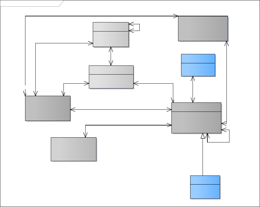
prEN 12896-1:2015 (E)
58
5.5.6 Generic Zone and Feature
5.5.6.1 Generic ZONE AND FEATURE – Conceptual Model
5.5.6.1.1 Zone – Conceptual Model
A ZONE is a two-dimension object used in the network description (e.g. administrative area, tariff zone,
flexible transport zone). ZONEs are classified according to a TYPE OF ZONE.
A ZONE may be defined by a GROUP OF POINTS belonging to the ZONE. For instance, a TARIFF ZONE
used to define a zonal fare structure in a zone-counting or zone-matrix system may be composed of a set of
stop points.
A ZONE may also be defined as a geometric area, bordered by a LINK SEQUENCE (a polygon). In such a
case, this LINK SEQUENCE has to be a closed one (i.e. the first and last POINTs IN LINK SEQUENCE must
be a view of the same POINT).
A ZONE may be recursive, and include other smaller ZONEs. This is expressed by the reflexive relationship
on ZONE.
A ZONE may be represented by a single POINT. Within one particular layer, this representing POINT has to
be unique.
class TM CC Generic Zone MODEL
ZONE
+ Name [0..1]
+ Description [0..1]
«UID»
+ Id
TYPE OF ZONE
«UID»
+ Id
CC Generic Point & Link
MODEL::POINT
CC Generic Point & Link
Sequence MODEL::LINK
SEQUENCE
CC Generic Point & Link
MODEL::GROUP OF POINTS
Name: TM CC Generic Zone MODEL
Author: Transmodel
Version: 1.0
Created: 05/02/2014 11:24:00
Updated: 21/05/2014 19:46:19
SIMPLE FEATURE
«UID»
+ Id
COMPLEX FEATURE
«UID»
+ Id
TARIFF ZONE
«UID»
+ Id
+viewed as
0..1
+a view of
*
+including
0..1
+included in *
+made up of
*
+contained in
*
+represented by 0..1
+functional centroid for
0..1
+included in
1..*
+composed of
*
+determining 0..1
+determined by
0..1
+viewed as
0..1
+a view of
*
+containing *
+contained in *
+bordered by
0..1
+border for 0..1
+a classification for
1
+classified as
*
+represented by
*
+representation
for
0..1
Figure 27 — Generic Zone – Conceptual Model

prEN 12896-1:2015 (E)
59
5.5.6.1.2 Feature – Conceptual Model
It is often necessary to define a group of objects of different types in a simpler representation, omitting the
details. For instance, a train station composed of tracks, platforms, vending machines, etc., or a depot
composed of halls, parking areas, lanes, maintenance facilities, etc., are viewed in some layers as single
POINTs. This is described by the entity COMPLEX FEATURE (named by analogy with the GDF standard and
usual GIS wording).
A COMPLEX FEATURE is composed of one or more SIMPLE FEATUREs. A SIMPLE FEATURE is identical
to an instance of either a POINT, a LINK, or a ZONE.
A COMPLEX FEATURE usually combines elements of different kinds such as POINTs, LINKs, ZONEs (each
of them not necessarily of the same type), and even other COMPLEX FEATUREs. It should not be mixed up
with a group of elements (e.g. GROUP OF POINTS), combining elements of one single type only (e.g. one
GROUP OF LINKs may be all LINKs in a tunnel, which is not a COMPLEX FEATURE).
As a ZONE, a COMPLEX FEATURE may be represented by a single POINT.
class TM CC Generic Feature MODEL
ZONE
+ Name [0..1]
+ Description [0..1]
«UID»
+ Id
CC Generic Point & Link
MODEL::POINT
Name: TM CC Generic Feature MODEL
Author: Transmodel
Version: 1.0
Created: 05/02/2014 20:20:34
Updated: 21/05/2014 19:21:26
SIMPLE FEATURE
«UID»
+ Id
COMPLEX FEATURE
«UID»
+ Id
CC Generic Point & Link
MODEL::LINK
+represented by
*
+representation
for
0..1
+including
0..1
+included in *
+viewed as
0..1
+a view of
*
+containing *
+contained in *
+made up of
*
+contained in
*
+viewed as 0..1
+a view of *
+start of
1
+from
*
+to
*
+end of
1
+represented by
0..1
+functional centroid for
0..1
+viewed as
0..1
+a view of
*
Figure 28 — Generic Feature – Conceptual Model
prEN 12896-1:2015 (E)
60
5.5.7 Generic Projection
5.5.7.1 Generic LAYER – Conceptual Model
Topological ENTITIES used for describing a transport network can be grouped into different LAYERs. Such
sets are actually VERSION FRAMEs with a specific property, namely each LAYER is associated with a one
and only one LOCATING SYSTEM, and the entities belonging to the LAYER have a position within this
LOCATING SYSTEM. Examples of layers include:
Infrastructure layer: describes road or rail network.
Route layer: describes route topology.
Service layer: describes network of stops served by routes.
Timing layer: describes location of timing points and times between them.
Different aspects of the network planning process deal with different layers of data. For instance, strategic
planning does not have to deal with details of the infrastructure like signals, switch points etc., but tactical
planning may very well have to do so.
Obviously there are many cases where information from different layers is needed to produce a result: e.g. a
map showing routes and stops needs to be drawn, distances between passenger stops need to be calculated
for statistical analysis etc.

prEN 12896-1:2015 (E)
61
class TM CC Generic Layer MODEL
Name: TM CC Generic Layer MODEL
Author: Transmodel
Version: 1.0
Created: 25/03/2014 12:28:13
Updated: 20/09/2014 09:38:15
CC Generic
Version Frame
MODEL::
VERSION FRAME
CC Generic
Version MODEL::
VERSION
CC Generic
Version MODEL::
ENTITY IN
VERSION
CC Generic
Validity MODEL::
VALIDITY
CONDITION
LAYER
«UID»
+ Id
CC Generic
Location MODEL::
LOCATING SYSTEM
CC Generic Grouping
MODEL::PURPOSE OF
GROUPING
CC Generic
Grouping MODEL::
GROUP OF ENTITIES
CC Generic Entity
MODEL::TYPE OF ENTITY
CC Generic Entity MODEL::
ENTITY
+characterised by
0..1
+defined for
*
+comprising
1
+belonging to
*
+governing
1
+governed by
1..*
+classified as
0..*
+a classification for
1
+base version for
0..1
+compatible with
0..*
+part of 0..*
+including 0..*
+valid instance of
*
+valid for
1
+parent of 0..1
+deriving from *
+parent of 0..1
+deriving
from *
+a classification for
1..*
+classified as
1..*
+made up of 0..*
+included in
1..*
+referenced by
0..*
+referencing
1
+allowed for
0..*
+restricted to
0..*
+comprising
0..*
+belonging to
0..*
+defined
for
0..*
+characterised by
1
+corresponding to
0..*
+implemented as
0..*
+representing
0..1
+represented by 1
+restricted to
1
+defined
for
*
Figure 29 — Generic Layer – Conceptual Model
5.5.7.2 Generic PROJECTION – Conceptual Model
The mechanism for relating ENTITIES of one LAYER to ENTITIES of another LAYER is called projection.
Projection can happen implicitly by transforming the entity position from the source LOCATION SYSTEM to
the destination LOCATION SYSTEM. However, there are cases where such automatic transformation is not
possible or practical, e.g. if a route needs to be displayed on a schematic map, there is no way of calculating
the positions from the spatial coordinates. Transmodel therefore contains a mechanism for explicitly projecting
(spatial) entities of one layer to another layer.

prEN 12896-1:2015 (E)
62
class TM CC Generic Projection MODEL
LINK PROJECTION
«UID»
+ Id
CC Generic Point
& Link MODEL::
POINT ON LINK
CC Generic
Point & Link
MODEL::POINT
CC Generic Point &
Link MODEL::LINK
POINT PROJECTION
+ Distance [0..1]
«UID»
+ Id
TYPE OF PROJECTION
ZONE PROJECTION
«UID»
+ Id
CC Generic Zone
and Feature
MODEL::ZONE
Name: TM CC Generic Projection MODEL
Author: Transmodel
Version: 1.0
Created: 05/02/2014 11:24:00
Updated: 29/08/2014 16:19:34
COMPLEX FEATURE
PROJECTION
«UID»
+ Id
CC Generic Point &
Link Sequence
MODEL::LINK
SEQUENCE
CC Generic Zone and Feature MODEL::COMPLEX FEATURE
{exclusion}
{exclusion}
{exclusion}
{exclusion}
+used as target in
1
+to *
+starting at
*
+start of
1
+used as
source in
1
+calling as
source
0..*
+concerning
*
+comprising
1
+used as target in
1
+to
*
+used as target in
1
+to *
+concerning *
+comprising
1
+used as target in
1
+to
*
+used as target in
1
+to
*
+used as target in
1
+to *
+concerning *
+comprising
1
+ending at
*
+end of
1
+used as
target in
1
+to
*
+used as target in
1
+to
*
+used as
source in
1
+calling as
source
*
+used as
source in
1
+calling as
source
0..*
+concerning
*
+comprising
1
+used as source in
1
+calling
as source
*
+used as target in
1
+to *
+used as target in 1
+to
*
Figure 30 — Generic Projection – Conceptual Model
5.5.7.2.1 Point Projection – Conceptual Model
Explicit projection is possible between POINTs, LINKs and ZONEs. The TYPE OF PROJECTION element
identifies the source and target layer of the projection and describes its purpose. A POINT may be related to a
POINT on a different layer, e.g. a timing point may be projected on a stop point.
The POINT PROJECTION is used to project a point of a source layer to an ENTITY of the target layer. The
target ENTITY can be a POINT or LINK, but not a ZONE. If the target of POINT PROJECTION is a link, the
distance from the start of the link is set in POINT PROJECTION.

prEN 12896-1:2015 (E)
63
class TM CC Point Projection MODEL
POINT PROJECTION
+ Distance [0..1]
«UID»
+ Id
TYPE OF PROJECTION
+ Name [0..1]
«UID»
+ Id
CC Generic Zone
and Feature
MODEL::COMPLEX
FEATURE
CC Generic Point & Link MODEL::POINT
CC Generic Point & Link
MODEL::LINK
CC Generic Point & Link Sequence
MODEL::LINK SEQUENCE
Name: TM CC Point Projection MODEL
Author: Transmodel
Version: 1.0
Created: 05/02/2014 11:24:00
Updated: 21/05/2014 19:55:51
{exclusion}
+containing *
+contained in *
+used as target in 1
+to *
+used as target in
1
+to *
+represented by
*
+representation for
0..1
+start of
1
+from *
+used as target in 1
+to
*
+concerning
*
+comprising
1
+used as target in
1
+to *
+to *
+end of
1
+used as
source in
1
+calling as source
0..*
Figure 31 — Point Projection – Conceptual Model
5.5.7.2.2 Link Projection – Conceptual Model
The LINK PROJECTION is used to project a LINK on one or more LINKs of another layer. As a precondition,
the destination link must have one or more POINT ON LINK entities associated with it. The start and end point
of the source link are projected on POINT ON LINK of the destination LINKs. An example of LINK projection
might be the projection of a LINK between two stops to the LINKs of the road (or rail).

prEN 12896-1:2015 (E)
64
class TM CC Link Projection MODEL
CC Generic Point & Link
MODEL::LINK
LINK PROJECTION
«UID»
+ Id
CC Generic Point & Link
Sequence MODEL::LINK
SEQUENCE
CC Generic Point & Link MODEL::
POINT ON LINK
CC Generic Zone
and Feature
MODEL::COMPLEX
FEATURE
Name: TM CC Link Projection MODEL
Author: Transmodel
Version: 1.0
Created: 05/02/2014 11:24:00
Updated: 22/05/2014 10:00:57
{exclusion}
+starting at
*
+start of
1
+passing
through
1
+located on
*
+used as source in
1
+calling as source
*
+ending at
*
+end of
1
+used as target in
1
+to
*
+containing *
+contained in *
+used as
target in
1
+to
*
Figure 32 — Link Projection – Conceptual Model
5.5.7.2.3 Zone Projection
A ZONE PROJECTION involves a ZONE as source. The projected ZONE may be targeting either one POINT
or one COMPLEX FEATURE.
The ZONE PROJECTION targeting a POINT expresses that the source ZONE is represented by a POINT in
the target layer.
The ZONE PROJECTION targeting a COMPLEX FEATURE means that the source ZONE belongs to the
COMPLEX FEATURE described in the target layer. This may be useful to express that a ZONE is represented
by a POINT, or that it represents the area in which all components of a COMPLEX FEATURE are located.
Some of these components may be changed without affecting the definition of the source ZONE.
5.5.7.2.4 Complex Feature Projection
A COMPLEX FEATURE PROJECTION involves a COMPLEX FEATURE as source. The projected
COMPLEX FEATURE can be targeting another COMPLEX FEATURE or a POINT.
The COMPLEX FEATURE conceptual Model is shown on the diagram Generic Projection – Conceptual Model
above.
The COMPLEX FEATURE PROJECTION targeting another COMPLEX FEATURE means that the source
feature is represented by the target feature, in the target layer. This may be useful if the level of complexity of
such COMPLEX FEATUREs is different (e.g. the target layer provides a simplified representation).
The COMPLEX FEATURE PROJECTION targeting to a POINT means that the target POINT represents, in
the target layer, all objects included in the COMPLEX FEATURE. This is a simplified representation of a
complex object. For instance a complex station description (including objects such as platforms or turnstiles)
may be represented in some LAYERs as a POINT.

prEN 12896-1:2015 (E)
65
Similar types of target for a COMPLEX FEATURE PROJECTION (not shown on the Generic Layer –
Conceptual Model, shown earlier) may be a LINK or a ZONE.
5.5.7.2.5 Shape of Linear Objects – Conceptual Model
Within a number of layers, a LINK is described as a straight line. However, a shape may be assigned to a
LINK, in order for instance to draw curves on a map. The concept LINE SHAPE, describes the graph to be
drawn between the limiting POINTs of the LINK, using a ‘formula’ recorded against this entity.
For instance, the model addresses several possibilities of assigning a shape to a LINK:
the LOCATING SYSTEM of a LAYER may allow describing a LINK as a curve (formula, etc.);
the projection modelling allows to project the LINK onto a sequence of consecutive straight segments
(called “edge” or “segmented line”, for instance) which belongs to another LAYER;
the projection modelling allows projecting the LINK onto a curvilinear feature, described in another
LAYER.
In the first example, the shape of the LINK is included in the considered layer; in the two other examples, the
LINK follows the shape of a linear feature described in another layer.
class TM CC Shape of Linear Objects MODEL
LINK PROJECTION
«UID»
+ Id
CC Generic Point &
Link MODEL::LINK
CC Generic
Location MODEL::
LOCATING
SYSTEM
LINE SHAPE
+ Formula
+ Name [0..1]
«UID»
+ Id
Name: TM CC Shape of Linear Objects MODEL
Author: Transmodel
Version: 1.0
Created: 05/02/2014 11:24:00
Updated: 29/08/2014 16:20:25
+for
*
+described by
1
+referring to
*
+reference for
1
+used as source in 1
+calling as source *
Figure 33 —Shape of Linear Objects – Conceptual Model

prEN 12896-1:2015 (E)
66
5.5.8 Generic Place
5.5.8.1 Generic PLACE – Conceptual Model
The PLACE model defines topographically significant places that a transport model may wish to describe. It
also allows the description of the possibility of connecting between them. A PLACE may be of dimension 0 (a
POINT), 1 (a road section) or 2 (a ZONE).
class TM CC Generic Place MODEL
CC Generic Point & Link
MODEL::POINT
ACCESS
«UID»
+ Id
TRANSFER
+ Name [0..1]
+ Description [0..1]
+ Distance [0..1]
+ BothWays [0..1]
+ DefaultDuration
+ FrequentTravellerDuration [0..1]
+ OccasionalTravellerDuration [0..1]
+ MobilityRestrictedTravellerDuration [0..1]
«UID»
+ Id
Name: TM CC Generic Place MODEL
Author: Transmodel
Version: 1.0
Created: 05/02/2014 11:24:00
Updated: 29/08/2014 18:47:44
PLACE
«UID»
+ Id
CC Generic Zone and
Feature MODEL::ZONE
TYPE OF PLACE
«UID»
+ Id
TYPE OF TRANSFER
«UID»
+ Id
TRANSFER END
ACCESS END
CC Generic Validity
MODEL::VALIDITY
CONDITION
{Transfer connect
either points or
zones}
{Access connects either
points or places}
CC Topographic
Place MODEL::
ADDRESSABLE
PLACE
+a view of 0..*
+viewed as 0..1
+part of 0..*
+including 0..*
+end of
1
+to
0..*
+start of
1
+from
0..*
+a view of 0..*
+viewed as
0..1
+end of
1
+to
0..*
+classified by
0..*
+a classification for
0..1
+applicable for 0..*
+ for 0..*
+a classification for
0..1
+classified by 0..*
+a view of
0..*
+viewed as
0..1
+described
by
0..1
+a generic
description of
0..1
+including
0..1
+included in *
+a view of
0..*
+viewed as
0..1
+start of
1
+from
0..*
+represented by
0..1
+functional centroid for
0..1
Figure 34 — Generic Place – Conceptual Model
5.5.9 Accessibility
Transmodel supports a detailed description of the accessibility of a site. This can be used in applications in
various ways:
For computable use the data can be used by a journey planner when calculating a journey that
meets a given set of user criteria, for example, to choose stations or paths that are wheelchair
accessible when planning a point-to-point journey and to direct a user to the entrances and exits most
suitable according to their needs.
prEN 12896-1:2015 (E)
67
For browsing/navigation the data can be used to show the exact properties of a given interchange
so that users may rehearse a trip ahead of making it and make their own judgment as to the best path
through an interchange.
.
In order to journey plan across data from different data systems, a uniform set of summary assessment
criteria is needed that can be used to establish possible routes of an equivalent level of accessibility. For
example, can a path be followed in a wheelchair, without using steps, etc.
5.5.9.1 ACCESSIBILITY – Conceptual Model
The accessibility of a site is described using an ACCESSIBILITY ASSESSMENT: this allows to express the
accessibility either in terms of suitability for specific USER NEEDs (using a SUITABILITY element) or in terms
of ACESSIBILITY LIMITATIONs, or both.
To describe accessibility, Transmodel models as separate and distinct aspects: (a) the description of the
USER’S NEEDs – for example wheelchair, hearing impaired, vision impaired, lift-averse, etc.; and (b) the
ACCESSIBILITY LIMITATION, i.e. description of the limitations of a site to support a specific need, for
example Wheelchair, Step free, Escalator free, Lift free – the last two also corresponding to some cognitive
aversions (e.g. sufferers of claustrophobia may dislike lifts). These aspects can be grouped together as an
ACCESSIBILITY ASSESSMENT and associated with various Transmodel topological concepts as this will be
shown in further parts of this standard.

prEN 12896-1:2015 (E)
68
class TM CC Accessibility MODEL
ACCESSIBILITY LIMITATION
WheelchairAccess [0..1]
StepFreeAccess [0..1]
EscalatorFreeAccess [0..1]
LiftFreeAccess [0..1]
AudibleSignsAvailable [0..1]
VisualSignsAvailable [0..1]
«UID»
Id
SUITABILITY
Suitable
«UID»
Id
USER NEED
Excluded
NeedRanking [0..1]
«UID»
Id
ACCESSIBILITY ASSESSMENT
MobilityImpairedAccess [0..1]
«UID»
Id
PASSENGER
ACCESSIBILITY NEED
Carer
«UID»
Id
TYPE OF ACCESSIBILITY
LIMITATION
«UID»
Id
Name: TM CC Accessibility MODEL
Author: Transmodel
Version: 1.0
Created: 05/02/2014 11:24:00
Updated: 29/08/2014 16:24:23
TYPE OF SUITABILITY
«UID»
Id
TYPE OF USER NEED
«UID»
Id
ENCUMBRANCE NEED
Need
«UID»
Id
MEDICAL NEED
Need
«UID»
Id
MOBILITY NEED
Need
«UID»
Id
PSYCHOSENSORY NEED
Need
«UID»
Id
VALIDITY CONDITION
determining
0..*
convenient for 1
classified by
0..*
a classification for
1
classified by
0..* a classification for
1
part of
0..*
including
0..*
determined for 1
determining 1..*
determining
0..*
determined by
1
determining
0..*
limited
by
1
classified by
0..*
a classification for
1
determining
0..*
determined by
0..*
Figure 35 — Accessibility – Conceptual Model

prEN 12896-1:2015 (E)
69
Certain of the ACCESSIBILITY LIMITATIONs are mutually exclusive – See Table 6.
Table 6 – Accessibility Attribute Constraints (source NeTEx)
LiftFree
StepFree
EscalatorFree
TravelatorFree
Criterion
Wheelchair
Wheelchair
access may
involve the use
of lifts
Wheelchair
access must be
step free
Wheelchair
access must be
escalator free
Wheelchair
access must be
travelator free
To be able to
drive a
wheelchair
unassisted
LiftFree
--
LiftFree
access may
involve the use
of steps
LiftFree
access may
involve the use
of escalators
LiftFree access
may involve the
use of
travelators
To avoid being
enclosed in a lift
StepFree
StepFree
access may
involve the use
of lifts
--
StepFree
access must be
escalator free
too
StepFree
access may still
involve the use
of travelators
To avoid routes
that demand
high mobility
EscalatorFree
EscalatorFree
access may
involve the use
of lifts
EscalatorFree
access may
involve the use
of steps
--
EscalatorFree
access may still
involve the use
of travelators
To avoid routes
that demand
high mobility
TravelatorFree
TravelatorFree
access may
involve the use
of lifts
TravelatorFree
access may
involve the use
of steps
TravelatorFree
access must be
escalator free
--
To avoid routes
that demand
high mobility
A detailed discussion of the different attributes and their values, on a concrete use of the different accessibility
characteristics is given in NeTEx-Part 1.
The MobilityImpairedAccess value provides an overall summary assessment of an element as accessible or not.
Table 7 shows suggested derivation from the lower level values.
Table 7 – Rules for summarizing Accessibility (source NeTEx)
Value
MobilityImpairedAccess
Wheelchair
false
false
true
true
unknown
false
LiftFree
false
No effect
true
No effect
unknown
No effect
StepFree
false
false
true
No effect
unknown
false
EscalatorFree
false
false
true
No effect
unknown
false
TravelatorFree
false
No effect
true
No effect
unknown
No effect
prEN 12896-1:2015 (E)
70
5.6 Reusable Components
The Reusable Components model defines common Public Transport related objects that can be used in any
other Transmodel package. The reusable components are not related to a specific PT topic, but are of general
relevance to a number of different topics.
5.6.1 Reusable Components – Model overview
The reusable components are modularized into separate sub-models, built on top of the common framework.
The main modules are:
TRANSPORT MODE Model – defines standard transport modes ;
TRANSPORT SUBMODE Model – defines standard transport submodes ;
SERVICE CALENDAR Model – defines concepts that allow to qualify temporal characteristics of
other concepts, in particular DAY TYPEs, OPERATING DAYs and SERVICE CALENDARs;
AVAILABILITY CONDITION Model – defines standardized temporal VALIDITY CONDITIONs;
TOPOGRAPHIC PLACE Model – defines named TOPOGRAPHIC PLACES that relate to places that
transport visits;
TRANSPORT ORGANISATION Model – defines OPERATORS, AUTHORITIES and other Transport
ORGANISATIONs;
ADDITIONAL ORGANISATION Model – defines SERVICED ORGANISATIONs and other non-
Transport ORGANISATIONs;
GENERIC EQUIPMENT Model – defines general EQUIPMENT , fixed and on-board EQUIPMENT;
ACTUAL VEHICLE EQUIPMENT Model – defines EQUIPMENT USAGE on a VEHICLE;
VEHICLE TYPE Model – Defines VEHICLE TYPES, VEHICLE Models and VEHICLEs;
VEHICLE PASSENGER EQUIPMENT Model – defines ACTUAL VEHICLE EQUIPMENT related to
vehicle accessibility;
FACILITY Model – defines simple service and facility categories;
TRAIN Model – defines train structure ;
SCHEMATIC MAP Model – defines general purpose SCHEMATIC MAP contents ;
NOTICE Model – defines footnotes and other NOTICEs;
SERVICE RESTRICTION Model – defines service or equipment usage restrictions in terms of fare-
related parameters;
ALTERNATIVE NAME Defines the different possible naming for PLACEs.

prEN 12896-1:2015 (E)
71
5.6.2 Transport Mode
5.6.2.1 TRANSPORT MODE – Conceptual Model
The MODE defines the mean of transport used or available. Transmodel subdivides the MODE into
TRANSPORT MODE, used inside public transport, and ACCESS MODE, used to join public transport (from
the start point of a journey, to the end point, during connections, etc.).
The entity TRANSPORT MODE refers to the classification of transport systems present in large cities or on
important transport corridors, for instance: bus, tramway, light rail, metro, long-distance rail, ferry.
A VEHICLE TYPE must belong to one TRANSPORT MODE. For instance, the “bus” TRANSPORT MODE will
gather standard, articulated, minibus, double-deck buses.
The ACCESS MODE is any out of vehicle mode used to reach a TRANSPORT MODE.
class TM CC Reusable Transport Mode MODEL
MODE
+ Name [0..1]
«UID»
+ Id
ACCESS MODE
«UID»
+ Id
VEHICLE MODE
«UID»
+ Id
Name: TM CC Reusable Transport Mode MODEL
Author: Transmodel
Version: 1.0
Created: 05/02/2014 11:24:00
Updated: 21/05/2014 23:23:20
foot
bicycle
taxi
boat
etc
air
rail
bus
coach
metro
etc
Figure 36 — Reusable Transport Mode – Conceptual Model
5.6.3 Transport SubMode
5.6.3.1 TRANSPORT SUBMODE – Conceptual Model
The SUBMODE model allows the TRANSPORT MODE to be further qualified by the specification of a
SUBMODE.

prEN 12896-1:2015 (E)
72
class TM CC Submode MODEL
CC Transport Mode MODEL:
:MODE
CC Transport Mode
MODEL::ACCESS
MODE
«UID»
+ Id
CC Transport Mode
MODEL::VEHICLE
MODE
«UID»
+ Id
Name: TM CC Submode MODEL
Author: Transmodel
Version: 1.0
Created: 06/02/2014 08:21:08
Updated: 21/05/2014 23:24:18
foot
bicycle
taxi
boat
etc
air
rail
bus
coach
metro
etc
SUBMODE
«UID»
+ Id
For the MODE "bus":
local bus,
regional bus,
etc
For the MODE "rail":
regional,
international ,
etc
+classified as
0..*
+a classification for
1
Figure 37 — Submode – Conceptual Model
5.6.4 Service Calendar
5.6.4.1 Introduction
The transport offering of a public transport company is tailored to accommodate different levels of demand. In
order to simplify the planning of supply almost all operators design their production plan using a classification
by type of day, which summarises the level of demand or other characteristics: for example, workday,
weekend, school holiday, market day, etc. Long-term planned schedules are designed through the so-called
transportation calendar, in which calendar days are classified as specific DAY TYPEs.
OPERATINGDAYs are in most cases similar to calendar days, with some possible differences (e.g. start and
end times). An assignment process of DAY TYPEs to OPERATING DAY allows selection of the most
appropriate schedules to meet the demand and face the traffic conditions. This leads to an operational plan for
every OPERATING DAY. The plan is completed by the assignment of physical resources to the theoretical
work and amended as necessary to deal with unexpected circumstances.
5.6.4.2 Service Calendar – Conceptual Model
5.6.4.2.1 Day Types
In Transmodel, a DAY TYPE is defined as a combination of various different properties a day may have, and
which will influence the transport demand and the running conditions (e.g. traffic flow for buses).
Any single condition that is relevant to the demand will be recorded as a particular PROPERTY OF DAY. For
example, “workday”, “Sunday”, “school holiday”, “market day” would each be a PROPERTY OF DAY. A
workday during school holidays, which is a market day, would be a DAY TYPE, formed with the combination
of those three PROPERTies OF DAY.
The most classical PROPERTY OF DAY is the DAY OF WEEK (e.g. “Wednesday”). A DAY TYPE may
associate different properties of the same type (e.g. “Tuesday or Thursday”).
The production elements designed during the planning process are characterized by a DAY TYPE and will be
used any day of operations to which this DAY TYPE is assigned.
prEN 12896-1:2015 (E)
73
5.6.4.2.2 Operating Days
The day of operation, considered from the point of view of the transportation process control, is described by
the entity OPERATING DAY.
The time limits of an OPERATING DAY will often deviate from the official date. One day of operation covers
for instance the period from 2.00 a.m. to 1.59 a.m. the day after, the period from 0.00 to 1.59 on the second
day being assigned to the operational day which started the day before.
Moreover, an OPERATING DAY may last more than 24 hours. It may be the case in some urban PT
operations, for which two OPERATING DAYs overlap during the night. It is more frequent in long-distance
railway operations, for which the journeys may last more than one day. However, in such a case, many
parameters, such as the schedules, the fares or the passenger information are still based on a DAY TYPE,
even if the DAY TYPEs and the OPERATING DAYs last more than 24 hours. The DAY TYPE assignment, in
such a case, is usually published as for the date of departure and the passengers invited to refer to this
assignment. Therefore, the date characterizing an OPERATING DAY corresponds to one of the calendar
dates covered by this OPERATING DAY, fixed arbitrarily and in most cases on the first calendar date.
A PERIOD is a continuous interval of several days between two particular OPERATING DAYs, which can be
used for several purposes (e.g. VALIDITY CONDITION of a VERSION).
5.6.4.2.3 Day Type Assignment
The production planning requires that a DAY TYPE is assigned to each OPERATING DAY, which is frequently
referred as a “transportation calendar” or – in The Conceptual Model – as a SERVICE CALENDAR. Ordinarily,
this is organized thanks to a default assignment table, which would apply to the whole network. This table
determines in advance the DAY TYPE that is valid in the network, for each OPERATING DAY of a given
period. This is expressed as a DAY TYPE ASSIGNMENT relationship between DAY TYPE and OPERATING
DAY.

prEN 12896-1:2015 (E)
74
class TM CC Serv ice Calendar MODEL
DAY TYPE
+ Name [0..1]
+ ShortName [0..1]
+ EarliestTime [0..1]
+ DayLength [0..1]
+ Description [0..1]
«UID»
+ Id
OPERATING DAY
+ CalendarDate
+ Name [0..1]
+ ShortName [0..1]
+ EarliestTime [0..1]
+ DayLength [0..1]
«UID»
+ Id
OPERATING PERIOD
+ Name [0..1]
+ HolidayType [0..*]
+ Season [0..*]
«UID»
+ Id
Name: TM CC Service Calendar MODEL
Author: Transmodel
Version: 1.0
Created: 05/02/2014 11:24:00
Updated: 29/08/2014 17:58:35
SERVICE CALENDAR
+ Name [0..1]
+ ShortName [0..1]
+ Description [0..1]
+ From
+ To
+ EarliestTime [0..1]
+ DayLength [0..1]
«UID»
+ Id
DAY TYPE ASSIGNMENT
+ Description [0..1]
+ IsAvailable [0..1]
+ Description [0..1]
+ Date [0..1]
«UID»
+ Id
PROPERTY OF DAY
+ Name [0..1]
+ Description [0..1]
+ WeekOfMonth [0..5]
+ DayOfYear [0..1]
+ Month [0..1]
+ Season [0..4]
+ HolidayType [0..5]
+ HolidayCountry [0..*]
+ Tide [0..4]
«UID»
+ Id
DAY OF WEEK
+ Name
«UID»
+ Day
GROUP OF TIMEBANDS
+ Name
«UID»
+ Id
TIME BAND
+ StartTime
+ EndTime
+ DayOffset [0..*]
+ Duration [0..*]
«UID»
+ Id
+made up of
0..1
+in
0..*
+specifying
*
+specified by
1
+used to define *
+defined as 0..1
+defined by
1
+for the definition of
0..*
+within
1
+ for
0..*
+the start day of
1
+starting at
0..*
+used to define 0..*
+for 0..*
+used
to
define
1
+for
*
+the end of
1
+ending at 0..*
+used to describe *
+described by *
+for the definition of
0..*
+defined
by
1
Figure 38 — Service Calendar – Conceptual Model
5.6.5 Availability Condition
5.6.5.1 AVAILABILITY CONDITION – Conceptual Model
AVAILABILITY CONDITION is a specialization of VALIDITY CONDITION to specify precise temporal
conditions. For example, an access to a station may be valid (it exists) but not available for some of the time
(it is closed between 9 pm and 6 am). Both VALIDITY CONDITIONs and AVAILABILITY CONDITIONs may
be associated for the same entity.
An AVAILABILITY CONDITION can be defined by specific DAY TYPEs and/or OPERATING DAYs. It may be
further qualified by one or more of TIME BANDs. The DATED AVAILABILITY CONDITION being the instance
of VALIDITY CONDITION on a specific CALENDAR DAY.
Examples of use of AVAILABILITY CONDITION include accesses to public transport network, equipment,
stopping places, etc.

prEN 12896-1:2015 (E)
75
class TM CC Availability Condition MODEL
CC Generic Validity MODEL::
VALIDITY CONDITION
AVAILABILITY CONDITION
+ IsAvailable [0..1]
+ FromDate [0..1]
+ ToDate [0..1]
«UID»
+ Id
CC Service
Calendar MODEL::
DAY TYPE
CC Service
Calendar
MODEL::
OPERATING DAYCC Service
Calendar
MODEL::TIME
BAND
Name: TM CC Availability Condition MODEL
Author: Transmodel
Version: 1.0
Created: 05/02/2014 11:24:00
Updated: 01/09/2014 14:54:14
CC Service Calendar
MODEL::OPERATING PERIOD
CC Service
Calendar MODEL::
DAY TYPE
ASSIGNMENT
CC Service Calendar
MODEL::PROPERTY OF
DAY
+part of 0..*
+including 0..*
+the start day of
1
+starting at
0..*
+determining 0..*
+valid for
0..*
+used to describe
*
+described by*
+specifying
*
+specified by 1
+determining 0..*
+valid for
0..*
+used to define 0..*
+for
0..*
+valid for
1..*
+characterized
by
0..*
+used to define
1
+for *
+the end of
1
+ending at
0..*
Figure 39 —Availability Condition – Conceptual Model
5.6.6 Topographic Place
5.6.6.1 TOPOGRAPHIC PLACE – Conceptual Model
The TOPOGRAPHIC PLACE model represents the named settlements and other places to which PT data
may be related. It also includes a an ADDRESS model, which can be used for stop finding and other
purposes.
A TOPOGRAPHIC PLACE may be located within one or more COUNTRies. TOPOGRAPHIC PLACEs may
overlap. They may also be contained inside another TOPOGRAPHIC PLACE.
ROAD ADDRESS and POSTAL ADDRESS can also be located within a COUNTRY.

prEN 12896-1:2015 (E)
76
class TM CC Topographic Place MODEL
TOPOGRAPHIC PLACE
+ Name
+ ShortName [0..1]
+ TopographicType
+ Qualifier [0..1]
+ Centre [0..1]
«UID»
+ Id
COUNTRY
+ Name
«UID»
+ Id
ADDRESS
+ ShortName [0..1]
«UID»
+ Id
POSTAL ADDRESS
+ HouseNumber [0..1]
+ BuildingName [0..1]
+ AddressLine1 [0..1]
+ Street [0..1]
+ Town [0..1]
+ PostCode [0..1]
+ PostCodeExtension [0..1]
+ Province [0..1]
«UID»
+ Id
ROAD ADDRESS
+ RoadNumber [0..1]
+ RoadName [0..1]
+ BearingCompass [0..1]
+ BearingDegrees [0..1]
+ OddNumberRange [0..1]
+ EvenNumberRange [0..1]
«UID»
+ Id
ZONE
CC Generic Place
MODEL::PLACE
«UID»
+ Id
ADDRESSABLE PLACE
+ Image [0..1]
+ Url [0..1]
+intersected
by
1..*
+intersecting 0..*
+part of
0..*
+primary for 1
+contained in
0..1
+containing
0..*
+adjacent to 0..*
+adjacent to 0..*
+described by
1
+describing 0..*
+hosting
1
+hosted by
0..*
Figure 40 — Topographic Place – Conceptual Model
5.6.7 Transport Organisations
The TRANSPORT ORGANISATION model defines organisations which run Public Transport, specifically
OPERATORs of Transport and the AUTHORITY. OPERATORs may be divided into OPERATING
DEPARTMENTs.
The generic term OPERATOR expresses a rather general responsibility for the operation of public transport
or, if it exists, for a concessionary contract for public transport. The direct operational responsibility for the
execution of this contract maybe handed to a specific OPERATING DEPARTMENT of the
ORGANISATIONAL UNIT. The OPERATOR acts as an alias for the ORGANISATIONAL UNIT. Part of the
contract-execution can be subcontracted to another OPERATOR. Or even the public transport for a whole
area can be divided into several contracts, where a GROUP OF OPERATORs are actually the executors of
the public transport timetables for a whole area.
5.6.7.1 TRANSPORT ORGANISATIONs – Conceptual Model
An ORGANISATION PART of an ORGANISATION acts as an ORGANISATIONAL UNIT responsible for the
determination of the PT Services, that need to be delivered in an OPERATIONAL CONTEXT often defined or
limited to one TRANSPORT MODE or even to one VEHICLE MODE or SUBMODE of one of its
DEPARTMENTs. This defines the actual involved OPERATING DEPARTMENT that will act as the serving
OPERATOR directly in charge of operations, and, when a contractual link to an AUTHORITY exists, for the
ordered services by the public transport AUTHORITY. The serving OPERATORs can be combined for
executing this service in a GROUP OF OPERATORS.
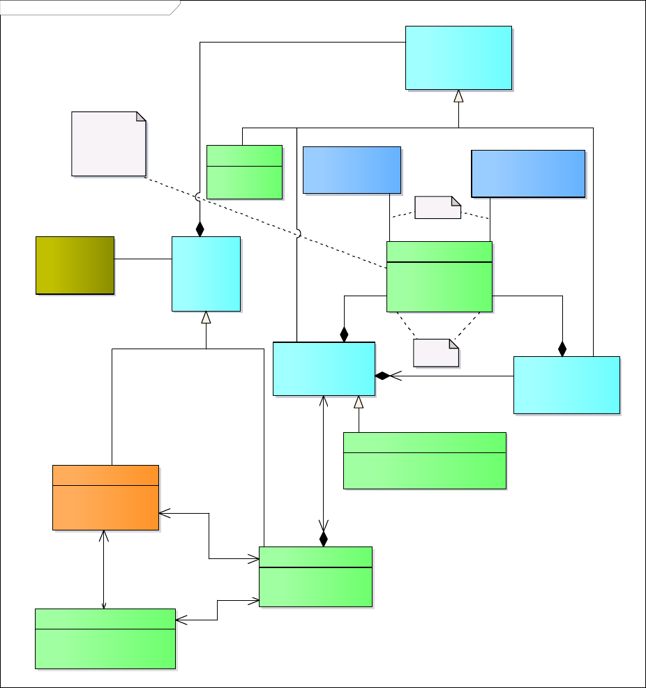
prEN 12896-1:2015 (E)
77
It is indeed possible to create a GROUP OF OPERATORs for a specific PURPOSE OF GROUPING, required
for special functions or processes in public transport, e.g. control of operations, fare collection, passenger
information, etc.
A CONTROL CENTRE is an organisational concept for where operational management takes place.
class TM CC Transport Organisation MODEL
GROUP OF OPERATORS
+ Category [0..1]
«UID»
+ Id
OPERATOR
+ PrimaryMode
«UID»
+ Id
AUTHORITY
«UID»
+ Id
CC Generic
Organisation
MODEL::
ORGANISATION
CC Generic Organisation
MODEL::ORGANISATION
PART
OPERATING DEPARTMENT
«UID»
+ Id
CC Generic Organisation
MODEL::ORGANISATIONAL
UNIT
CC Generic Organisation
MODEL::DEPARTMENT
OPERATIONAL CONTEXT
+ Name [0..1]
+ ShortName [0..1]
«UID»
+ Id
exclusion
characterization of
operation related
group of objects,
often linked to the
transport mode.
CC Transport Submode
MODEL::SUBMODE
MODE
CC Transport Mode
MODEL::VEHICLE MODE
ADDRESS
CC Topographic
Place MODEL::
POSTAL ADDRESS
CONTROL CENTRE
«UID»
+ Id
{exclusion}
Name: TM CC Transport Organisation MODEL
Author: Transmodel
Version: 1.0
Created: 05/02/2014 11:24:00
Updated: 21/05/2014 23:29:40
+serving PT for 0..*
+ordering PT
service from
*
+determined by
0..*
+determining
+determining 1
+determined by
0..*
+locating
1
+located at
0..*
+determined by
0..*
+determining
+serving PT for
*
+ordering PT service
from
*
+determining
1
+determined by
0..*
+owner of
1
+owned by
1..*
+part of
0..*
+made up of
1
+part of
1..*
+comprising
1
+grouping
*
+grouped in
1..*
Figure 41 — Transport Organisations – Conceptual Model
5.6.8 Additional Organisations
5.6.8.1 ADDITIONAL ORGANISATIONs – Conceptual Model
The ADDITIONAL ORGANISATION model describes additional ORGANISATION types other than
OPERATOR & AUTHORITY, but that are also related to the execution of part of the public transport services.

prEN 12896-1:2015 (E)
78
The model depicts them as different institutions, so with the alias OTHER ORGANISATION it pictures the
possible relationships that can be involved in various types of the execution of a public transport contract.
A TRAVEL AGENT takes reservations.
A MANAGEMENT AGENT operates on behalf of another organisation, for example to collect data.
A SERVICED ORGANISATION is an organisation for whom a transport service is provided, for example a
school or works and for which the schedule may vary according to whether the organisation is open for
business. This is described through the ORGANISATION DAY TYPE (inheriting from DAY TYPE) and
SERVICE CALENDAR for a given OPERATNG PERIOD, with DAY TYPE ASSIGNMENT.
An ORGANISATION can be reached at a POSTAL ADDRESS and can be made up of several
ORGANISATIONAL PARTs.
class TM CC Additional Organisation MODEL
TRAVEL AGENT
«UID»
+ Id
OTHER
ORGANISATION
«UID»
+ Id
MANAGEMENT
AGENT
«UID»
+ Id
SERVICED
ORGANISATION
«UID»
+ Id
CC Generic Organisation
MODEL::ORGANISATION
CC Generic
Organisation
MODEL::
ORGANISATION
PART
CC Generic Organisation
MODEL::ORGANISATIONAL
UNIT
CC Transport
Organisations MODEL::
OPERATOR
CC Transport
Organisations MODEL::
AUTHORITY
Name: TM CC Additional Organisation MODEL
Author: Transmodel
Version: 1.0
Created: 05/02/2014 11:24:01
Updated: 20/09/2014 09:41:12
ADDRESS
CC Topographic
Place MODEL::
POSTAL ADDRESS
ORGANISATION DAY
TYPE
+ IsServiceDay [0..1]
«UID»
+ Id
CC Service Calendar
MODEL::DAY TYPE
CC Service Calendar
MODEL::OPERATING
PERIOD
CC Service Calendar
MODEL::SERVICE
CALENDAR
CC Service
Calendar MODEL::
DAY TYPE
ASSIGNMENT
+serving PT for
*
+ordering PT
service from
*
+within
1
+ for 0..*
+serviced on
1
+for
0..*
+locating
1
+located at
0..*
+part of
0..*
+made up of
1
+serviced according to
0..*
+serviced for 0..*
+specifying
*
+specified by
1
+defined by
1
+for the
definition of
0..*
Figure 42 — Additional Organisations – Conceptual Model
prEN 12896-1:2015 (E)
79
5.6.9 Generic Equipment
5.6.9.1 Generic EQUIPMENT – Conceptual Model
The Generic EQUIPMENT Model represents items of equipment which may be located on a vehicle or at a
site. There are many different types of EQUIPMENT, each of which may have specific properties. These are
classified under two main specializations;
INSTALLED EQUIPMENT, fixed EQUIPMENT that may be installed on a site, such as a door, lift,
gate etc. or on a VEHICLE. This is further characterized into:
o PLACE EQUIPMENT: equipment which may be located only on a fixed site, such as a barrier,
bench, lift and of which the location may be specified by an EQUIPMENT PLACE;
o ACTUAL VEHICLE EQUIPMENT: an item of equipment of a particular type actually installed
on board an individual vehicle;
o PASSENGER EQUIPMENT: equipment which may be located on either a vehicle or a site,
such as a display terminal, ticket validator or WC.
LOCAL SERVICE: an intangible service that is provided at a site such as selling tickets, porterage,
etc.

prEN 12896-1:2015 (E)
80
class TM CC Generic Equipment MODEL
PLACE EQUIPMENT
+ Units [0..1]
«UID»
+ Id
Name: TM CC Generic Equipment MODEL
Author: Transmodel
Version: 1.0
Created: 17/02/2014 10:32:25
Updated: 29/08/2014 19:00:19
EQUIPMENT
+ Name [0..1]
+ Description [0..1]
+ Note [0..1]
+ Image [0..1]
+ InfoLink [0..1]
- OutOfService [0..1]
«UID»
+ Id
LOCAL SERVICE
«UID»
+ Id
INSTALLED EQUIPMENT
«UID»
+ Id
TYPE OF EQUIPMENT
«UID»
+ Id
CC Actual Vehicle
Equipment MODEL::
ACTUAL VEHICLE
EQUIPMENT
PASSENGER EQUIPMENT
+ Fixed [0..1]
«UID»
+ Id
CC Vehicle Type MODEL::
VEHICLE
PLACE
EQUIPMENT is
fixed
ACTUAL VEHICLE
EQUIPMENT
is installed on-board
CC Generic Accessibility
MODEL::ACCESSIBILITY
ASSESSMENT
CC Generic Validity
MODEL::VALIDITY
CONDITION
{exclusion: this
equipment is either
fixed or on-board}
+in 0..*
+equipped with
1
+used as
0..1
+using 0..1
+part of 0..*
+including 0..*
+located at
0..*
+equipped with
0..1
+a classification for
1
+classified
as
*
+used as
0..1
+using
0..1
+determining 0..*
+determined by 0..*
+for
0.. 1
+suitable 0..1
Figure 43 — Generic Equipment – Conceptual Model
5.6.9.2 Vehicle Equipment – Conceptual Model
ACTUAL VEHICLE EQUIPMENT can be used to specify the EQUIPMENT available on a VEHICLE of a
specific VEHICLE TYPE.

prEN 12896-1:2015 (E)
81
class TM CC Vehicle Equipment MODEL
PLACE EQUIPMENT
+ Units [0..1]
«UID»
+ Id
Name: TM CC Vehicle Equipment MODEL
Author: Transmodel
Version: 1.0
Created: 05/02/2014 11:24:01
Updated: 29/08/2014 19:01:01
EQUIPMENT
+ Name [0..1]
+ Description [0..1]
+ Note [0..1]
+ Image [0..1]
+ InfoLink [0..1]
- OutOfService [0..1]
«UID»
+ Id
LOCAL SERVICE
«UID»
+ Id
INSTALLED EQUIPMENT
«UID»
+ Id
TYPE OF EQUIPMENT
«UID»
+ Id
CC Actual Vehicle Equipment
MODEL::ACTUAL VEHICLE
EQUIPMENT
CC Vehicle Type MODEL::VEHICLE
PASSENGER EQUIPMENT
+ Fixed [0..1]
«UID»
+ Id
CC Vehicle Type MODEL::
VEHICLE TYPE
CC Facility
MODEL::
FACILITY
FACILITY SET
CC Facility MODEL::SERVICE
FACILITY SET
CC Generic
Accessibility MODEL::
ACCESSIBILITY
ASSESSMENT
{exclusion: this
equipment is either
fixed or on-board}
+a classification
for
1
+classified as
*
+part of
1..*
+comprising
0..1
+a
classification
for
1
+classified
as
*
+made up of
0..1
+included in *
+used as
0..1
+using
0..1
+present
at
0..*
+comprising 0..1
+located at
0..*
+equipped with
0..1
+for 0.. 1
+suitable 0..1
+used as
0..1
+using
0..1
+in 0..*
+equipped with
1
Figure 44 —Vehicle Equipment – Conceptual Model

prEN 12896-1:2015 (E)
82
5.6.10 Vehicle Type
5.6.10.1 VEHICLE TYPE – Conceptual Model
The VEHICLE entity is used to describe the physical public transport vehicles available for short-term planning
of operations and daily assignment (in contrast to logical vehicles considered for resource planning). Each
VEHICLE must be classified as of a particular VEHICLE TYPE.
The VEHICLE TYPE Model represents a description of VEHICLES through their properties.
VEHICLES may be classified according to the vehicle scheduling requirements as to model and capacity and
on board facilities (e.g. standard bus, double-deck, etc.).
class TM CC Vehicle Type MODEL
VEHICLE
+ Name [0..1]
+ ShortName [0..1]
«UID»
+ Id
INSTALLED EQUIPMENT
CC Actual Vehicle Equipment
MODEL::ACTUAL VEHICLE
EQUIPMENT
VEHICLE EQUIPMENT
PROFILE
+ Name [0..1]
+ Units [0..1]
«UID»
+ Id
VEHICLE MODEL
+ Name [0..1]
+ Description [0..1]
+ Manufacturer [0..1]
«UID»
+ Id
VEHICLE TYPE
+ Name [0..1]
+ ShortName [0..1]
+ Description [0..1]
+ ReversingDirection [0..1]
+ SelfPropelled [0..1]
+ Length [0..1]
+ TypeOfFuel [0..1]
+ SeatingCapacity [0..1]
+ StandingCapacity [0..1]
+ SpecialPlaceCapacity [0..1]
+ WheelchairPlaceCapacity [0..1]
+ LowFloor [0..1]
+ HasLiftOrRamp [0..1]
«UID»
+ Id
Name: TM CC Vehicle Type MODEL
Author: Transmodel
Version: 1.0
Created: 05/02/2014 11:24:01
Updated: 29/08/2014 19:05:47
PURPOSE OF EQUIPMENT
PROFILE
«UID»
+ Id
CC Generic Equipment
MODEL::TYPE OF
EQUIPMENT
CC Generic Accessibility
MODEL::ACCESSIBILITY
ASSESSMENT
CC Facility MODEL::
SERVICE FACILITY
SET
CC Facility
MODEL::
FACILITY SET
PASSENGER CARRYING
REQUIREMENT
+ MinimumCapacity
+ LowFloor [0..1]
+ HasLiftOrRamp [0..1]
«UID»
+ Id
MANOEUVRING REQUIREMENT
+ Reversable [0..1]
+ MinimumTurningCircle [0..1]
+ MinimumLength [0..1]
+ MinimumOvertakingWidth [0..1]
«UID»
+ Id
FACILITY REQUIREMENT
+ serviceFacilitySets [0..*]
«UID»
+ Id
+present at
0..*
+comprising
0..1
+for
0.. 1
+suitable
0..1
+a classification for 1
+classified
as
*
+made up of 0..1
+included in *
+classifying
0..1
+classified
as
*
+in 0..*
+equipped with
1
+a classification for
1
+classified as
*
+for 0..*
+satisfying 0..*
+requirement for
0..*
+satisfying
+defining 1
+defined
for
*
+satisfying
0..*
+for
0..*
+a classification for
1
+classified
as
*
+ for
0..*
+satisfying 0..*
+in
1..*
+equipped with
1
Figure 45 — Vehicle Type – Conceptual Model

prEN 12896-1:2015 (E)
83
5.6.11 Actual Vehicle Equipment
5.6.11.1 ACTUAL VEHICLE EQUIPMENT – Conceptual Model
The ACTUAL VEHICLE EQUIPMENT specifies the type of EQUIPMENT to use in a given VEHICLE.
class TM CC Actual Vehicle Equipment MODEL
CC Generic Equipment
MODEL::EQUIPMENT
CC Generic
Equipment MODEL::
INSTALLED
EQUIPMENT
CC Generic Equipment
MODEL::TYPE OF
EQUIPMENT
ACTUAL VEHICLE EQUIPMENT
+ Units [0..1]
«UID»
+ Id
Name: TM CC Actual Vehicle Equipment MODEL
Author: Transmodel
Version: 1.0 (corrected)
Created: 05/02/2014 11:24:01
Updated: 20/09/2014 09:26:52
CC Vehicle Type MODEL::
VEHICLE
CC Vehicle Type
MODEL::VEHICLE
MODEL
CC Vehicle Type
MODEL::VEHICLE TYPE
CC Vehicle Type MODEL::
VEHICLE EQUIPMENT
PROFILE
CC Generic Accessibility
MODEL::ACCESSIBILITY
ASSESSMENT
+a classification for
1
+classified as
*
+classifying
0..1
+classified
as
*
+a classification for
1
+classified as
*
+in
1..*
+equipped with
1
+for
0.. 1
+suitable
0..1
+in
0..*
+equipped with
1
+a classification for
1
+classified as
*
+a classification for 1
+classified as
*
+made up of
0..1
+included in *
Figure 46 — Actual Vehicle Equipment – Conceptual Model
5.6.12 Vehicle Passenger Equipment
5.6.12.1 Vehicle Passenger Equipment – Conceptual Model
Boarding properties of a VEHICLE are described by two specialisations of the ACTUAL VEHICLE
EQUIPMENT:
- WHEELCHAIR VEHICLE EQUIPMENT describes on-board capacity for wheelchairs;
- VEHICLE ACCESS EQUIPMENT describes on-board equipment allowing to access vehicles e.g. low floor,
ramp, access area with adapted dimensions, etc.

prEN 12896-1:2015 (E)
84
class TM CC Vehicle Passenger Equipment MODEL
Name: TM CC Vehicle Passenger Equipment MODEL
Author: Transmodel
Version: 1.0
Created: 05/02/2014 11:24:01
Updated: 29/08/2014 19:10:42
CC Generic Equipment
MODEL::EQUIPMENT
VEHICLE ACCESS EQUIPMENT
LowFloor [0..1]
Ramp [0..1]
RampBearingCapacity [0..1]
NumberOfSteps [0..1]
BoardingHeight [0..1]
GapToPlatform [0..1]
WidthOfAccessArea [0..1]
HeightOfAccessArea [0..1]
AutomaticDoors [0..1]
SuitableFor [0..*]
AssistanceNeeded [0..1]
AssistedBoardingLocation [0..1]
GuideDogsAllowed [0..1]
«UID»
Id
WHEELCHAIR VEHICLE
EQUIPMENT
NumberOfWheelchairAreas [0..1]
WidthOfAccessArea [0..1]
HeightOfAccessArea [0..1]
LengthOfAccessArea [0..1]
WheelchairTurningCircle [0..1]
CompanionSeat [0..1]
SuitableFor [0..*]
«UID»
Id
CC Actual Vehicle
Equipment MODEL::
ACTUAL VEHICLE
EQUIPMENT
CC Generic
Equipment MODEL::
INSTALLED
EQUIPMENT
CC Generic
Accessibility MODEL::
ACCESSIBILITY
ASSESSMENT
for
0.. 1
suitable
0..1
Figure 47 — Vehicle Passenger Equipment – Conceptual Model
5.6.13 Facility
5.6.13.1 FACILITY – Conceptual Model
A FACILITY provides just a simple name of a capability. Detailed properties may be stated for some types of
facilities by a corresponding EQUIPMENT type.
FACILITies are combined into FACILITY SETs – reusable standard combinations of facilities.
A SERVICE FACILITY SET describes a set of FACILITIES for use on a service. It can include information
about the ACCOMMODATION on board. A SITE FACILITY SET describes a set of FACILITIES available at a
fixed place.

prEN 12896-1:2015 (E)
85
class TM CC Facility MODEL
FACILITY
«UID»
+ Id
FACILITY SET
+ Description [0..1]
«UID»
+ Id
SERVICE FACILITY SET
«UID»
+ Id
SITE FACILITY SET
«UID»
+ Id
CC Vehicle Type
MODEL::VEHICLE
TYPE
Name: TM CC Facility MODEL
Author: Transmodel
Version: 1.0
Created: 06/02/2014 12:19:06
Updated: 01/09/2014 15:26:24
ACCOMODATION
+ FareClass [0..1]
+ AccommodationFacility [0..1]
+ Name [0..1]
+ CouchetteFacility [0..1]
+ ShowerFacility [0..1]
+ ToiletFacility [0..1]
+ Gender [0..1]
+ BerthType [0..1]
+ NuisanceFacility [0..*]
«UID»
+ Id
ONBOARD STAY
+ FareClass [0..1]
+ Permission [0..1]
+ Duration [0..1]
«UID»
+ Id
CC Generic Validity
MODEL::VALIDITY
CONDITION
TYPE OF
FACILITY
«UID»
+ Id
+present at
0..*
+comprising
0..1
+included
in
1..*
+comprising
0..1
+made up of 0..1
+included in *
+avalable if
0..1
+determining
availability of
0..*
+classified as
0..*
+a classification for
0..1
+part of
1..*
+comprising
0..1
+part of 0..* +including 0..*
Figure 48 — Facility – Conceptual Model
5.6.14 Train
5.6.14.1 TRAIN – Conceptual Model
The TRAIN Conceptual model represents VEHICLE TYPE properties that are peculiar to TRAINs. A TRAIN
may comprise not just a single VEHICLE but a chain of carriages, TRAIN ELEMENTS, assembled as TRAIN
COMPONENTs. Groups of carriages may be managed as sections by composing TRAINs into a
COMPOUND TRAIN made up of TRAINs IN COMPOUND TRAIN, for example in a Train that joins or splits.
TRAIN ELEMENTS can be classified with a TYPE OF TRAIN.
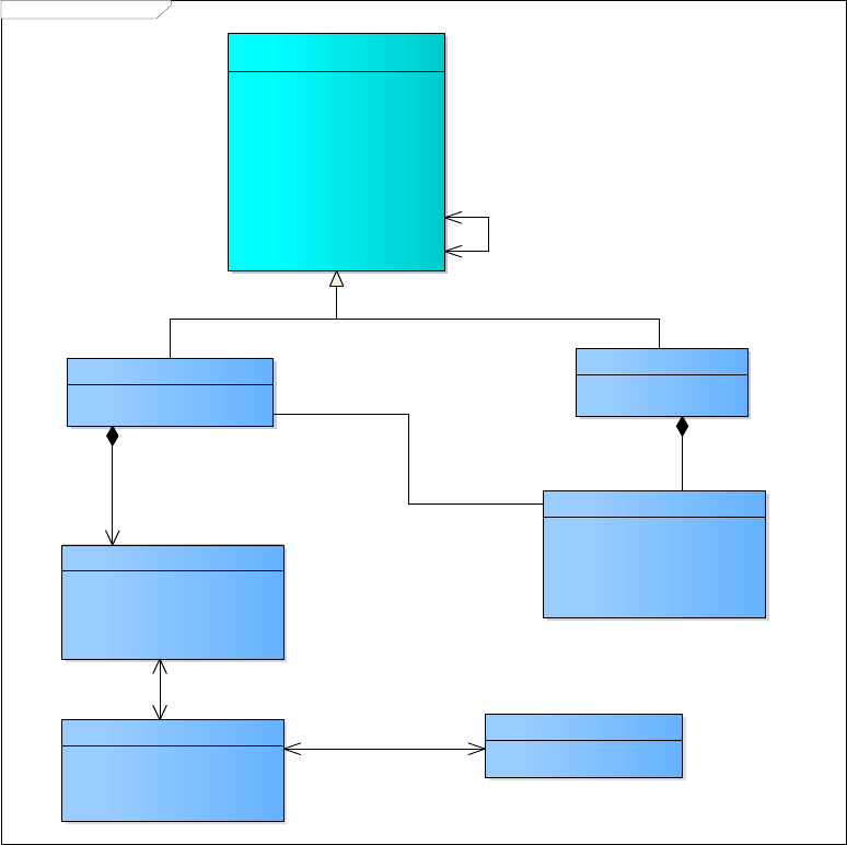
prEN 12896-1:2015 (E)
86
class TM CC Train MODEL
TRAIN COMPONENT
+ Order
+ Name [0..1]
+ Description [0..1]
+ Label [0..1]
«UID»
+ Id
TRAIN ELEMENT
+ Name [0..1]
+ Description [0..1]
+ Length [0..1]
«UID»
+ Id
TYPE OF TRAIN ELEMENT
«UID»
+ Id
TRAIN
«UID»
+ Id
CC Vehicle Type MODEL::VEHICLE
TYPE
+ Name [0..1]
+ ShortName [0..1]
+ Description [0..1]
+ ReversingDirection [0..1]
+ SelfPropelled [0..1]
+ Length [0..1]
+ TypeOfFuel [0..1]
+ SeatingCapacity [0..1]
+ StandingCapacity [0..1]
+ SpecialPlaceCapacity [0..1]
+ WheelchairPlaceCapacity [0..1]
+ LowFloor [0..1]
+ HasLiftOrRamp [0..1]
«UID»
+ Id
TRAIN IN COMPOUND TRAIN
+ Order
+ Description [0..1]
+ OperationalOrientation [0..1]
+ ReversedOrientation [0..1]
+ Label [0..1]
«UID»
+ Id
COMPOUND TRAIN
«UID»
+ Id
Name: TM CC Train MODEL
Author: Transmodel
Version: 1.0
Created: 14/05/2014 14:13:55
Updated: 01/09/2014 16:15:47
+using
*
+used for 1
+made up of 0..1
+included in *
+used for
1
+using
*
+used
for
*
+composed
of
1
+classification for
1
+classified as
*
+used for
*
+composed of
1
Figure 49 — Train – Conceptual Model

prEN 12896-1:2015 (E)
87
5.6.14.2 Example of a Train
The following figure shows how a train can be represented as an ordered collection of TRAIN COMPONENTs.
Figure 50 — Train Elements Example (source NeTEx)
The following figure shows a real life example of a Train Makeup.
prEN 12896-1:2015 (E)
88
Figure 51 — Eurostar Train Makeup (source NeTEx)
5.6.15 Schematic Map
5.6.15.1 SCHEMATIC MAP – Conceptual Model
The published passenger Information for a complex transport interchange often includes schematic maps to
show the relative parts and facilities located within the interchange. In an interactive presentation to
passengers using an electronic device, these maps may be linked to other elements, for example, to see the
properties of a piece of equipment.
Transmodel includes a generic representation of such a map that may be linked to different Transmodel
topological elements as further model parts will show it.

prEN 12896-1:2015 (E)
89
class TM CC Schematic Map MODEL
SCHEMATIC MAP
+ Name [0..1]
+ ImageUri [0..1]
«UID»
+ Id
Name: TM CC Schematic Map MODEL
Author: Transmodel
Version: 1.0
Created: 06/02/2014 21:05:21
Updated: 21/05/2014 23:42:28
ZONE
CC Generic
Place MODEL::
PLACE
«UID»
+ Id
+depicted by 0..*
+depicting 0..*
Figure 52 — Schematic Map – Conceptual Model
The following figures show examples of a SCHEMATIC MAP for the PLACE Wimbledon station.
Figure 53 — Wimbledon Station plan: Ground floor (NRE Stations Made Easy) –(source NeTEx)

prEN 12896-1:2015 (E)
90
5.6.16 Notice
5.6.16.1 NOTICE – Conceptual Model
The NOTICE Model defines reusable text note elements that may be attached to timetables as footnotes,
used as announcements, etc. NOTICES are associated with other entities using a NOTICE ASSIGNMENT.
NOTICES may be classified with a TYPE OF NOTICE.
Each NOTICE may have several alternative formats as specified by a DELIVERY VARIANT.
class TM CC Notice MODEL
NOTICE
+ Name [0..1]
+ Text [0..1]
+ CanBeAdvertised [0..1]
+ DriverDisplayText [0..1]
«UID»
+ Id
DELIVERY VARIANT
+ VariantText [0..1]
«UID»
+ Id
TYPE OF DELIVERY
VARIANT
«UID»
+ Id
TYPE OF NOTICE
«UID»
+ Id
Name: TM CC Notice MODEL
Author: Transmodel
Version: 1.0
Created: 05/02/2014 11:24:01
Updated: 01/09/2014 16:18:54
+providing
0..*
+provided as
1
+classiifed as
0..*
+a classification for
0..1
+classified as
0..*
+a classification for 0..1
Figure 54 — Notice – Conceptual Model
5.6.17 Service Restriction
5.6.17.1 SERVICE RESTRICTION - Conceptual Model
Figure 55 defines some parameters describing the limitations as regards the use of equipment or service:
- CLASS OF USE represents the fare class e.g. first class, business class, economy class, etc;
- PAYMENT METHOD is the way the service is paid: cash, coin, credit card, cheque, etc
- TYPE OF TICKET may be a standard ticket (without any reduction), a concession, a season ticket, a group
ticket, etc
- TICKET SCOPE is the broad geographic validity if the ticket: local, national, international.

prEN 12896-1:2015 (E)
91
class TM CC Serv ice Restriction MODEL
SERVICE RESTRICTION
CLASS OF USE
«UID»
+ Id
TYPE OF FARE
CLASS
«UID»
+ Id
TYPE OF
PAYMENT
METHOD
«UID»
+ Id
TYPE OF TICKET
«UID»
+ Id
TYPE OF
TICKETING
«UID»
+ Id
Name: TM CC Service Restriction MODEL
Author: Transmodel
Version: 1.0
Created: 05/02/2014 11:24:01
Updated: 20/09/2014 09:22:36
TICKET SCOPE
«UID»
+ Id
«enumeration»
AccessRightValues::
PaymentMethod Enum
cash
cashAndCard
coin
banknote
creditCard
debitCard
contactlessPaymentCard
cardsOnly
travelCard
contactlessTravelCard
sms
mobilePhone
cheque
companyCheque
travellersCheque
postalOrder
voucher
token
warrant
other
«enumeration»
AccessRightValues::
TicketTypeEnum
standard
promotion
concession
group
season
travelCard
other
«enumeration»
AccessRightValues::
PaymentMethod Enum::
TicketScopeEnum
localTicket
nationalTicket
internationalTicket
«enumeration»
AccessRightValues::
F areClassEnum
firstClass
secondClass
thirdClass
economyClass
businessClass
turista
preferente
Parameters describing limitations for use
of services (or equipment) such as the
following :
Figure 55— Service Restriction – Conceptual Model
5.6.18 Alternative Name
5.6.18.1 ALTERNATIVE NAME – Conceptual Model
ALTERNATIVE NAME presents a generic mechanism used to provide aliases i.e. alternative names for data
elements.

prEN 12896-1:2015 (E)
92
class TM CC Alternative Name MODEL
ALTERNATIVE NAME
+ NameType [0..1]
+ ShortName [0..1]
+ Abbreviation [0..1]
+ Name [0..1]
+ QualifierName [0..1]
«UID»
+ Id
CC Generic Entity MODEL::
ENTITY
+ Changed
+ Created
«UID»
+ Id
Name: TM CC Alternative Name MODEL
Author: Transmodel
Version: 1.0
Created: 20/02/2014 00:23:27
Updated: 01/09/2014 16:25:25
ALTERNATIVE NAME is a
generic mechanism used
to provide alternative
names for elements
+alias for 0..*
+provided with
1
Figure 56 — Alternative Name – Conceptual Model

prEN 12896-1:2015 (E)
93
Appendix A – Data Dictionary
ACCESS (CC Generic Place MODEL)
The physical (spatial) possibility for a passenger to access or leave the public transport system. This link may
be used during a trip for:- the walking movement of a passenger from a PLACE (origin of the trip) to a
SCHEDULED STOP POINT (origin of the PT TRIP), or- the walking movement from a SCHEDULED STOP
POINT (destination of the PT TRIP) to a PLACE (destination of the trip).
Inherits from (empty if no inheritance): TRANSFER
Classifi-
cation
Name
Type
cardinality
«UID»
Id
1:1
ACCESS END (CC Generic Place MODEL)
Origin or destination end of an ACCESS link. May indicate a POINT and/or PLACE.
Inherits from (empty if no inheritance):
Classifi-
cation
Name
Type
cardinality
ACCESS MODE (CC Transport Mode MODEL)
A characterisation of the passenger movement according to the means of transport different from public
transport (e.g. walk, bicycle, etc)
Inherits from (empty if no inheritance): MODE
Classifi-
cation
Name
Type
cardinality
«UID»
Id
1:1
ACCESSIBILITY ASSESSMENT (CC Generic Accessibility MODEL)
The accessibility characteristics of an entity used by passengers such as a STOP PLACE, or a STOP PLACE
COMPONENT. Described by ACCESSIBILITY LIMITATIONs, and/or a set of SUITABILITies
Inherits from (empty if no inheritance):
Classifi-
cation
Name
Type
cardinality
«UID»
Id
1:1
MobilityImpairedAccess
boolean
0:1
ACCESSIBILITY LIMITATION (CC Generic Accessibility MODEL)
A categorisation of the accessibility characteristics of a SITE, e.g. a STOP PLACE or a STOP PLACE
COMPONENT to indicate its usability by passengers with specific needs, for example, those needing
wheelchair access, step-free access or wanting to avoid confined spaces such as lifts. A small number of well-
defined categories are used that are chosen to allow the consistent capture of data and the efficient
computation of routes for different classes of user.

prEN 12896-1:2015 (E)
94
Inherits from (empty if no inheritance):
Classifi-
cation
Name
Type
cardinality
«UID»
Id
1:1
WheelchairAccess
LimitationStatusEnum
0:1
StepFreeAccess
LimitationStatusEnum
0:1
EscalatorFreeAccess
LimitationStatusEnum
0:1
LiftFreeAccess
LimitationStatusEnum
0:1
AudibleSignsAvailable
LimitationStatusEnum
0:1
VisualSignsAvailable
LimitationStatusEnum
0:1
ACCOMODATION (CC Facility MODEL)
A combination of accommodation characteristics available on a service, e.g. "First Class Couchette with
shower and 2 bunks".
Inherits from (empty if no inheritance): SERVICE FACILITY SET
Classifi-
cation
Name
Type
cardinality
«UID»
Id
FareClass
FareClassEnum
0:1
AccommodationFacility
AccommodationFacilityEnum
0:1
Name
MultilingualString
0:1
CouchetteFacility
CouchetteFacilityEnum
0:1
ShowerFacility
SanitaryFacilityEnum
0:1
ToiletFacility
SanitaryFacilityEnum
0:1
Gender
GenderLimitationEnum
0:1
BerthType
BerthTypeEnum
0:1
NuisanceFacility
NuisanceFacilityEnum
0:*
ACTUAL VEHICLE EQUIPMENT (CC Actual Vehicle Equipment MODEL)
An item of equipment of a particular type in an individual VEHICLE.
Inherits from (empty if no inheritance): INSTALLED EQUIPMENT
Classifi-
cation
Name
Type
cardinality
«UID»
Id
1:1
Units
nonNegativeInteger
0:1
ADDRESS (CC Topographic Place MODEL)
The descriptive data associated with a PLACE that can be used to describe the unique geographical context
of a PLACE for the purposes of identifying it. May be refined as either a ROAD ADDRESS, a POSTAL
ADDRESS or both.
Inherits from (empty if no inheritance):
Classifi-
cation
Name
Type
cardinality
«UID»
Id
1:1
ShortName
MultilingualString
0:1

prEN 12896-1:2015 (E)
95
ADDRESSABLE PLACE (CC Topographic Place MODEL)
A type of PLACE to which passengers may refer to indicate the origin or a destination of a trip and that is so
specific that it has an ADDRESS.
Inherits from (empty if no inheritance): PLACE
Classifi-
cation
Name
Type
cardinality
Image
anyUri
0:1
Url
anyUri
0:1
ADMINISTRATIVE ZONE (CC Generic Organisation MODEL)
The area of a district, a region, a city, a municipality, or other area with which an ORGANIZATION has a
RESPONSIBILITY ROLE;
Inherits from (empty if no inheritance): ZONE
Classifi-
cation
Name
Type
cardinality
«UID»
id
1:1
ShortName
MultilingualString
0:1
ALTERNATIVE NAME (CC Alternative Name MODEL)
Alternative name for the entity.
Inherits from (empty if no inheritance):
Classifi-
cation
Name
Type
cardinality
«UID»
Id
1:1
NameType
NameTypeEnum
0:1
ShortName
MultilingualString
0:1
Abbreviation
MultilingualString
0:1
Name
MultilingualString
0:1
QualifierName
MultilingualString
0:1
AUTHORITY (CC Transport Organisations MODEL)
The organisation under which the responsibility of organising the transport service in a certain area is placed.
Inherits from (empty if no inheritance): ORGANISATION
Classifi-
cation
Name
Type
cardinality
«UID»
Id
1:1
AVAILABILITY CONDITION (CC Availability Condition MODEL)
A VALIDITY CONDITION expressed in terms of temporal parameters and referring to DAY TYPEs.

prEN 12896-1:2015 (E)
96
Inherits from (empty if no inheritance): VALIDITY CONDITION
Classifi-
cation
Name
Type
cardinality
«UID»
Id
1:1
IsAvailable
boolean
0:1
FromDate
dateTime
0:1
ToDate
dateTime
0:1
CLASS IN FRAME (CC Generic Version Frame MODEL)
The different CLASSEes IN REPOSITORY which can be relevant for corresponding VERSION FRAMEs.
Inherits from (empty if no inheritance):
Classifi-
cation
Name
Type
cardinality
«UID»
Id
1:1
CLASS IN REPOSITORY (CC Generic Entity MODEL)
Any ENTITY name belonging to the repository. e.g. DAY TYPE, PROPERTY OF DAY, TIME BAND,
VEHICLE TYPE, etc, are relevant instances of CLASS IN REPOSITORY in the context of version
management.
Inherits from (empty if no inheritance):
Classifi-
cation
Name
Type
cardinality
«UID»
Id
NameOfClass
1:1
CLASS OF USE (CC Service Restriction MODEL)
A classification of fare and other service classes by category of user entitled to use them.
Inherits from (empty if no inheritance): SERVICE RESTRICTION
Classifi-
cation
Name
Type
cardinality
«UID»
Id
1:1
COMPLEX FEATURE (CC Generic Zone and Feature MODEL)
An aggregate of SIMPLE FEATUREs and/or other COMPLEX FEATUREs.
Inherits from (empty if no inheritance):
Classifi-
cation
Name
Type
cardinality
«UID»
Id
1:1
COMPLEX FEATURE PROJECTION (CC Generic Projection MODEL)
An oriented correspondence: from one COMPLEX FEATURE in the source layer, onto an entity in a target
layer: e.g. POINT, COMPLEX FEATURE, within a defined TYPE OF PROJECTION.

prEN 12896-1:2015 (E)
97
Inherits from (empty if no inheritance):
Classifi-
cation
Name
Type
cardinality
«UID»
Id
1:1
COMPOSITE FRAME (CC Composite Frame MODEL)
A set of VERSION FRAMEs to which the same VALIDITY CONDITIONs have been assigned.
Inherits from (empty if no inheritance): VERSION FRAME
Classifi-
cation
Name
Type
cardinality
«UID»
Id
1:1
COMPOUND TRAIN (CC Train MODEL)
A VEHICLE TYPE composed of a sequence of more than one vehicles of the type TRAIN.
Inherits from (empty if no inheritance): VEHICLE TYPE
Classifi-
cation
Name
Type
cardinality
«UID»
Id
1:1
CONTACT DETAILS (CC Generic Organisation MODEL)
Contact details for ORGANISATION for public use.
Inherits from (empty if no inheritance):
Classifi-
cation
Name
Type
cardinality
«UID»
Id
1:1
ContactPerson
normalizedString
0:1
Email
EmailAddressType
0:1
Fax
PhoneNumberType
0:1
FurtherDetails
xsd:string
0:1
Phone
PhoneNumberType
0:1
Url
anyURI
0:1
CONTROL CENTRE (CC Transport Organisations MODEL)
An ORGANISATION PART for an operational team who are responsible for issuing commands to control the
services.
Inherits from (empty if no inheritance): ORGANISATION PART
Classifi-
cation
Name
Type
cardinality
«UID»
Id
1:1
COUNTRY (CC Topographic Place MODEL)
A jurisdictional geographic boundary. A COUNTRY normally has a two character IANA identifier.

prEN 12896-1:2015 (E)
98
Inherits from (empty if no inheritance):
Classifi-
cation
Name
Type
cardinality
«UID»
Id
CountryEnum
1:1
Name
MultilingualString
1:1
DATA SOURCE (CC Generic Responsibility MODEL)
The DATA SOURCE identifies the system which has produced the data. References to a data source are
useful in an interoperated computer system.
Inherits from (empty if no inheritance):
Classifi-
cation
Name
Type
cardinality
«UID»
Id
1:1
Email
emailType
0:1
DAY OF WEEK (CC Service Calendar MODEL)
A particular week day (from Monday to Sunday).
Inherits from (empty if no inheritance):
Classifi-
cation
Name
Type
cardinality
«UID»
Day
1:1
Name
MultilingualString
1:1
DAY TYPE (CC Service Calendar MODEL)
A type of day characterised by one or more properties which affect public transport operation. For example:
weekday in school holidays.
Inherits from (empty if no inheritance):
Classifi-
cation
Name
Type
cardinality
«UID»
Id
1:1
Name
MultilingualString
0:1
ShortName
MultilingualString
0:1
EarliestTime
time
0:1
DayLength
duration
0:1
Description
MultilingualString
0:1
DAY TYPE ASSIGNMENT (CC Service Calendar MODEL)
The assignment of operational characteristics, expressed by DAY TYPEs, to particular OPERATING DAYs
within a SERVICE CALENDAR.

prEN 12896-1:2015 (E)
99
Inherits from (empty if no inheritance):
Classifi-
cation
Name
Type
cardinality
«UID»
Id
1:1
Description
MultilingualString
0:1
IsAvailable
boolean
0:1
Description
MultilingualString
0:1
Date
date
0:1
DELIVERY VARIANT (CC Notice MODEL)
A variant text of a NOTICE for use in a specific media or delivery channel (voice, printed material, etc).
Inherits from (empty if no inheritance):
Classifi-
cation
Name
Type
cardinality
«UID»
Id
DeliveryIdVariantType
1:1
VariantText
MultilingualString
0:1
DELTA (CC Generic Delta MODEL)
A record of the detailed changes of a given ENTITY IN VERSION from one VERSION to the next one. A
DELTA contains pairs of attributes' old values - new values.
Inherits from (empty if no inheritance):
Classifi-
cation
Name
Type
cardinality
«UID»
Id
1:1
DeltaValue
1:1
DEPARTMENT (CC Generic Organisation MODEL)
An ORGANIZATION PART specific to a purpose and/or organisational structure.
Inherits from (empty if no inheritance): ORGANISATION PART
Classifi-
cation
Name
Type
cardinality
«UID»
Id
1:1
Name
MultilingualString
1:1
ENCUMBRANCE NEED (CC Generic Accessibility MODEL)
A specific USER NEED, i.e. a requirement of a passenger travelling with luggage, animal or any other object
requiring special arrangements to access public transport.
Inherits from (empty if no inheritance): TYPE OF USER NEED
Classifi-
cation
Name
Type
cardinality
«UID»
Id
1:1
Need
EncumbranceNeedEnum
1:1

prEN 12896-1:2015 (E)
100
ENTITY (CC Generic Entity MODEL)
Any data instance to be managed in an operational Version Management System. When several data sources
coexist (multimodality and/or interoperability), an ENTITY has to be related to a given DATA SOURCE in
which it is defined.
Inherits from (empty if no inheritance):
Classifi-
cation
Name
Type
cardinality
«UID»
Id
1:1
Changed
dateTime
1:1
Created
dateTime
1:1
ENTITY IN VERSION (CC Generic Version MODEL)
The ENTITY associated to a given VERSION.
Inherits from (empty if no inheritance):
Classifi-
cation
Name
Type
cardinality
«UID»
Id
1:1
Modification
ModificationEnum
0:1
EQUIPMENT (CC Generic Equipment MODEL)
An item of equipment installed either fixed (PLACE EQUIPMENT) or on-board vehicles (VEHICLE
EQUIPMENT). A service (LOCAL SERVICE such as LEFT LUGGAGE, TICKETING SERVICE) is considered
as immaterial equipment as well.
Inherits from (empty if no inheritance):
Classifi-
cation
Name
Type
cardinality
«UID»
Id
1:1
Name
MultilingualString
0:1
Description
MultilingualString
0:1
Note
MultilingualString
0:1
Image
anyURI
0:1
InfoLink
InfoLink
0:1
OutOfService
boolean
0:1
FACILITY (CC Facility MODEL)
A named amenity available to the public at a SITE or on a SERVICE. A facility has no further properties other
than a name. An EQUIPMENT or LOCAL SERVICE is used to describe the further properties provided as part
of particular facility.
Inherits from (empty if no inheritance):
Classifi-
cation
Name
Type
cardinality
«UID»
Id
1:1
FACILITY REQUIREMENT (CC Vehicle Type MODEL)
A classification of public transport vehicles according to the facilities available on the vehicle.

prEN 12896-1:2015 (E)
101
Inherits from (empty if no inheritance):
Classifi-
cation
Name
Type
cardinality
«UID»
Id
1:1
serviceFacilitySets
ServiceFacilitySet
0:*
FACILITY SET (CC Facility MODEL)
Set of FACILITies available for a SERVICE JOURNEY or a JOURNEY PART. The set may be available only
for a specific VEHICLE TYPE within the SERVICE (e.g. carriage equipped with low floor).
Inherits from (empty if no inheritance):
Classifi-
cation
Name
Type
cardinality
«UID»
Id
1:1
Description
MultilingualString
0:1
GENERAL FRAME (CC General Frame MODEL)
Set of data containing information, to which the same VALIDITY CONDITIONs have been assigned.
Inherits from (empty if no inheritance): VERSION FRAME
Classifi-
cation
Name
Type
cardinality
«UID»
Id
1:1
GROUP OF ENTITIES (CC Generic Grouping MODEL)
A set of ENTITies grouped together according to a PURPOSE OF GROUPING, e.g. grouping of stops known
to the public by a common name.
Inherits from (empty if no inheritance):
Classifi-
cation
Name
Type
cardinality
«UID»
Id
1:1
Name
MultilingualString
0:1
Description
MultilingualString
0:1
ShortName
MultilingualString
0:1
GROUP OF LINK SEQUENCES (CC Generic Point & Link Sequence MODEL)
A grouping of LINK SEQUENCEs.
Inherits from (empty if no inheritance):
Classifi-
cation
Name
Type
cardinality
«UID»
Id
1:1
GROUP OF LINKS (CC Generic Point & Link MODEL)
A grouping of LINKs. e.g. one GROUP OF LINKs may be managed by a same AUTHORITY.

prEN 12896-1:2015 (E)
102
Inherits from (empty if no inheritance):
Classifi-
cation
Name
Type
cardinality
«UID»
Id
1:1
GROUP OF OPERATORS (CC Transport Organisations MODEL)
A group of OPERATORs having for instance common schemes for fare collection or passenger information.
Inherits from (empty if no inheritance):
Classifi-
cation
Name
Type
cardinality
«UID»
Id
1:1
Category
normalizedString
0:1
GROUP OF POINTS (CC Generic Point & Link MODEL)
A grouping of POINTs of a certain TYPE OF POINT and dedicated to a FUNCTIONAL PURPOSE.
Inherits from (empty if no inheritance):
Classifi-
cation
Name
Type
cardinality
«UID»
Id
1:1
GROUP OF TIMEBANDS (CC Service Calendar MODEL)
A grouping of TIME BANDs.
Inherits from (empty if no inheritance):
Classifi-
cation
Name
Type
cardinality
«UID»
Id
1:1
Name
1:1
INSTALLED EQUIPMENT (CC Generic Equipment MODEL)
An item of equipment either fixed (PLACE EQUIPMENT) or on board i.e. associated with vehicles. This
equipment is materialised as opposed to a service (LOCAL SERVICE) considered as an immaterial
equipment.
Inherits from (empty if no inheritance): EQUIPMENT
Classifi-
cation
Name
Type
cardinality
«UID»
Id
1:1
LAYER (CC Generic Layer MODEL)
A user-defined GROUP OF ENTITies, specified for a particular functional purpose, associating data referring
to a particular LOCATING SYSTEM.

prEN 12896-1:2015 (E)
103
Inherits from (empty if no inheritance): GROUP OF ENTITIES
Classifi-
cation
Name
Type
cardinality
«UID»
Id
1:1
LINE SHAPE (CC Generic Projection MODEL)
The graphical shape of a LINK obtained from a formula or other means, using the LOCATION of its limiting
POINTs and depending on the LOCATING SYSTEM used for the graphical representation.
Inherits from (empty if no inheritance):
Classifi-
cation
Name
Type
cardinality
«UID»
Id
1:1
Formula
Name
1:1
Name
normalizedString
0:1
LINK (CC Generic Point & Link MODEL)
An oriented spatial object of dimension 1 with view to the overall description of a network, describing a
connection between two POINTs.
Inherits from (empty if no inheritance):
Classifi-
cation
Name
Type
cardinality
«UID»
Id
1:1
Name
MultilingualString
0:1
Distance
DistanceType
0:1
LINK IN LINK SEQUENCE (CC Generic Point & Link Sequence MODEL)
The order of a LINK in a LINK SEQUENCE to which it belongs.
Inherits from (empty if no inheritance):
Classifi-
cation
Name
Type
cardinality
«UID»
Id
1:1
Order
positiveInteger
1:1
LINK PROJECTION (CC Generic Projection MODEL)
An oriented correspondence from one LINK of a source layer, onto an entity in a target layer: e.g. LINK
SEQUENCE, COMPLEX FEATURE, within a defined TYPE OF PROJECTION.
Inherits from (empty if no inheritance):
Classifi-
cation
Name
Type
cardinality
«UID»
Id
1:1

prEN 12896-1:2015 (E)
104
LINK SEQUENCE (CC Generic Point & Link Sequence MODEL)
An ordered sequence either of POINTs or of LINKs, defining a path through the network.
Inherits from (empty if no inheritance):
Classifi-
cation
Name
Type
cardinality
«UID»
Id
1:1
Name
MultilingualString
0:1
ShortName
MultilingualString
0:1
Distance
DistanceType
0:1
LOCAL SERVICE (CC Generic Equipment MODEL)
A named service relating to the use of the SITE or transport services at a particular location, for example
porterage, assistance for disabled users, booking offices etc. The service may have a VALIDITY CONDITION
associated with it. A LOCAL SERVICE is treated as a form of immaterial EQUIPMENT.
Inherits from (empty if no inheritance): EQUIPMENT
Classifi-
cation
Name
Type
cardinality
«UID»
Id
1:1
LOCATING SYSTEM (CC Generic Location MODEL)
The system used as reference for location and graphical representation of the network and other spatial
objects.
Inherits from (empty if no inheritance):
Classifi-
cation
Name
Type
cardinality
«UID»
Id
1:1
LocatingSystemName
LocatingSystemNameType
1:1
LOCATION (CC Generic Location MODEL)
The position of a POINT with a reference to a given LOCATING SYSTEM (e. g. coordinates).
Inherits from (empty if no inheritance):
Classifi-
cation
Name
Type
cardinality
«UID»
Id
1:1
Coordinates
CordinateString
0:1
Latitude
LatitudeType
0:1
Longitude
LongitudeType
0:1
Altitude
LengthType
0:1
Precision
decimal
0:1
MANAGEMENT AGENT (CC Additional Organisation MODEL)
Specialisation of ORGANISATION for MANAGEMENT AGENTs.

prEN 12896-1:2015 (E)
105
Inherits from (empty if no inheritance): OTHER ORGANISATION
Classifi-
cation
Name
Type
cardinality
«UID»
Id
1:1
MANOEUVRING REQUIREMENT (CC Vehicle Type MODEL)
A classification of requirements for a public transport VEHICLE according to the Maneuvering capabilities of
the vehicle.
Inherits from (empty if no inheritance):
Classifi-
cation
Name
Type
cardinality
«UID»
Id
1:1
Reversable
boolean
0:1
MinimumTurningCircle
LengthType
0:1
MinimumLength
LengthType
0:1
MinimumOvertakingWidth
LengthType
0:1
MEDICAL NEED (CC Generic Accessibility MODEL)
A specific USER NEED, i.e. a requirement of a passenger as regards medical constraint (e.g. allergy) to
access public transport .
Inherits from (empty if no inheritance): TYPE OF USER NEED
Classifi-
cation
Name
Type
cardinality
«UID»
Id
1:1
Need
MedicalNeedEnum
1:1
MOBILITY NEED (CC Generic Accessibility MODEL)
A specific USER NEED, i.e. a constraint of a passenger as regards his mobility, e.g. wheelchair, assisted
wheelchair, etc.
Inherits from (empty if no inheritance): TYPE OF USER NEED
Classifi-
cation
Name
Type
cardinality
«UID»
Id
1:1
Need
MobilityNeedEnum
1:1
MODE (CC Transport Mode MODEL)
Any means of transport.
Inherits from (empty if no inheritance):
Classifi-
cation
Name
Type
cardinality
«UID»
Id
1:1
Name
MultilingualString
0:1

prEN 12896-1:2015 (E)
106
NOTICE (CC Notice MODEL)
A text for informational purposes on exceptions in a LINE, a JOURNEY PATTERN, etc. The information may
be usable for passenger or driver information.
Inherits from (empty if no inheritance):
Classifi-
cation
Name
Type
cardinality
«UID»
Id
1:1
Name
MultilingualString
0:1
Text
MultilingualString
0:1
CanBeAdvertised
boolean
0:1
DriverDisplayText
MultilingualString
0:1
ONBOARD STAY (CC Facility MODEL)
Permission to board early before the journey or stay on board after the journey.
Inherits from (empty if no inheritance): SERVICE FACILITY SET
Classifi-
cation
Name
Type
cardinality
«UID»
Id
1:1
FareClass
FareClassEnum
0:1
Permission
BoardingPermisssionEnum
0:1
Duration
duration
0:1
OPERATING DAY (CC Service Calendar MODEL)
A day of public transport operation of which the characteristics are defined within in a specific SERVICE
CALENDAR. An OPERATING DAY may last more than 24 hours.
Inherits from (empty if no inheritance):
Classifi-
cation
Name
Type
cardinality
«UID»
Id
1:1
CalendarDate
date
1:1
Name
MultilingualString
0:1
ShortName
MultilingualString
0:1
EarliestTime
time
0:1
DayLength
duration
0:1
OPERATING DEPARTMENT (CC Transport Organisations MODEL)
A specific DEPARTMENT which administers certain LINEs.
Inherits from (empty if no inheritance): DEPARTMENT
Classifi-
cation
Name
Type
cardinality
«UID»
Id
1:1
OPERATING PERIOD (CC Service Calendar MODEL)
A continuous interval of time between two OPERATING DAYs which will be used to define validities.
prEN 12896-1:2015 (E)
107
Inherits from (empty if no inheritance):
Classifi-
cation
Name
Type
cardinality
«UID»
Id
1:1
Name
MultilingualString
0:1
HolidayType
HolidayTypeEnum
0:*
Season
SeasonEnum
0:*
OPERATIONAL CONTEXT (CC Transport Organisations MODEL)
Characterization of a set of operational objects, such as timing or links determined either by a DEPARTMENT
or by an ORGANISATIONAL UNIT.
Inherits from (empty if no inheritance):
Classifi-
cation
Name
Type
cardinality
«UID»
Id
1:1
Name
normalizedString
0:1
ShortName
MultilingualString
0:1
OPERATOR (CC Transport Organisations MODEL)
A company providing public transport services.
Inherits from (empty if no inheritance): ORGANISATION
Classifi-
cation
Name
Type
cardinality
«UID»
Id
1:1
PrimaryMode
VehicleModeEnum
1:1
ORGANISATION (CC Generic Organisation MODEL)
A legally incorporated body associated with any aspect of the transport system.
Inherits from (empty if no inheritance):
Classifi-
cation
Name
Type
cardinality
«UID»
Id
1:1
Description
MultilingualString
0:1
LegalName
MultilingualString
0:1
Name
normalizedString
1:1
Remarks
MultilingualString
0:1
ShortName
MultilingualString
0:1
TradingName
MultilingualString
0:1
Status
boolean
0:1
ValidFromDate
date
0:1
ValidToDate
date
0:1
ORGANISATION DAY TYPE (CC Additional Organisation MODEL)
DAY TYPE that is defined in terms of operation or not operation of a referenced SERVICED ORGANISATION.

prEN 12896-1:2015 (E)
108
Inherits from (empty if no inheritance): DAY TYPE
Classifi-
cation
Name
Type
cardinality
«UID»
Id
1:1
IsServiceDay
boolean
0:1
ORGANISATION PART (CC Generic Organisation MODEL)
A part of an ORGANISATION to which specific responsibilities upon the data and data management may be
assigned.
Inherits from (empty if no inheritance):
Classifi-
cation
Name
Type
cardinality
«UID»
Id
1:1
Name
MultilingualString
0:1
ShortName
MultilingualString
0:1
Description
MultilingualString
0:1
ORGANISATIONAL UNIT (CC Generic Organisation MODEL)
An ORGANISATION PART to which a set of responsibilities in a public transport company for planning and
control is assigned.
Inherits from (empty if no inheritance): ORGANISATION PART
Classifi-
cation
Name
Type
cardinality
«UID»
Id
1:1
OTHER ORGANISATION (CC Additional Organisation MODEL)
Generic ORGANISATION being neither an AUTHORITY, neither a public transport OPERATOR (TRAVEL
AGENT, MANAGEMENT AGENT, etc.).
Inherits from (empty if no inheritance): ORGANISATION
Classifi-
cation
Name
Type
cardinality
«UID»
Id
1:1
PASSENGER ACCESSIBILITY NEED (CC Generic Accessibility MODEL)
A passenger's requirement for accessibility, comprising one or more USER NEEDs. For example, that he is
unable to navigate stairs, or lifts, or has visual or auditory impairments. PASSENGER ACCESSIBILITY
NEEDS can be used to derive an accessibility constraint for the passenger, allowing the computation of paths
for passengers with specifically constrained mobility. Example: Wheelchair, No Lifts, No Stairs.
Inherits from (empty if no inheritance):
Classifi-
cation
Name
Type
cardinality
«UID»
Id
1:1
Carer
boolean
1:1

prEN 12896-1:2015 (E)
109
PASSENGER CARRYING REQUIREMENT (CC Vehicle Type MODEL)
A classification of requirements for a public transport vehicle according to the passenger carrying capabilities
of the vehicle.
Inherits from (empty if no inheritance):
Classifi-
cation
Name
Type
cardinality
«UID»
Id
1:1
MinimumCapacity
PassengerCapacity
1:1
LowFloor
boolean
0:1
HasLiftOrRamp
boolean
0:1
PASSENGER EQUIPMENT (CC Generic Equipment MODEL)
An item of equipment of a particular type actually available at a location within a PLACE or a VEHICLE.
Inherits from (empty if no inheritance): INSTALLED EQUIPMENT
Classifi-
cation
Name
Type
cardinality
«UID»
Id
1:1
Fixed
boolean
0:1
PLACE (CC Generic Place MODEL)
A geographic place of any type which may be specified as the origin or destination of a trip. A PLACE may be
represented as a POINT (dimension 0) , a road section (dimension 1) or a ZONE (dimension 2).
Inherits from (empty if no inheritance): ZONE
Classifi-
cation
Name
Type
cardinality
«UID»
Id
1:1
PLACE EQUIPMENT (CC Generic Equipment MODEL)
An item of equipment of a particular type actually available at a location within a PLACE.
Inherits from (empty if no inheritance): INSTALLED EQUIPMENT
Classifi-
cation
Name
Type
cardinality
«UID»
Id
1:1
Units
nonNegativeInteger
0:1
POINT (CC Generic Point & Link MODEL)
A 0-dimensional node of the network used for the spatial description of the network. POINTs may be located
by a LOCATION in a given LOCATING SYSTEM.
Inherits from (empty if no inheritance):
Classifi-
cation
Name
Type
cardinality
«UID»
Id
1:1
Name
MultilingualString
0:1

prEN 12896-1:2015 (E)
110
POINT IN LINK SEQUENCE (CC Generic Point & Link Sequence MODEL)
A POINT in a LINK SEQUENCE indicating its order in that particular LINK SEQUENCE.
Inherits from (empty if no inheritance):
Classifi-
cation
Name
Type
cardinality
«UID»
Id
1:1
Order
positiveInteger
1:1
POINT ON LINK (CC Generic Point & Link MODEL)
A POINT on a LINK which is not needed for LINK definition, but may be used for other purposes, e.g. for
purposes of automatic vehicle monitoring, passenger information or for driver information.
Inherits from (empty if no inheritance):
Classifi-
cation
Name
Type
cardinality
«UID»
Id
1:1
Name
MultilingualString
0:1
Order
Integer
1:1
DistanceFromStart
Distance
0:1
POINT PROJECTION (CC Generic Projection MODEL)
An oriented correspondence from one POINT of a source layer, onto a entity in a target layer: e.g. POINT,
LINK, LINK SEQUENCE, COMPLEX FEATURE, within a defined TYPE OF PROJECTION.
Inherits from (empty if no inheritance):
Classifi-
cation
Name
Type
cardinality
«UID»
Id
1:1
Distance
DistanceType
0:1
POSTAL ADDRESS (CC Topographic Place MODEL)
A specification of ADDRESS refining it by using the attributes used for conventional identification for mail.
Comprises variously a building Identifier, Street name, Post code and other descriptors.
Inherits from (empty if no inheritance): ADDRESS
Classifi-
cation
Name
Type
cardinality
«UID»
Id
1:1
HouseNumber
normalizedString
0:1
BuildingName
normalizedString
0:1
AddressLine1
normalizedString
0:1
Street
normalizedString
0:1
Town
normalizedString
0:1
PostCode
PostCodeType
0:1
PostCodeExtension
normalizedString
0:1
Province
normalizedString
0:1

prEN 12896-1:2015 (E)
111
PROPERTY OF DAY (CC Service Calendar MODEL)
A property which a day may possess, such as school holiday, weekday, summer, winter etc.
Inherits from (empty if no inheritance):
Classifi-
cation
Name
Type
cardinality
«UID»
Id
1:1
Name
MultilingualString
0:1
Description
MultilingualString
0:1
WeekOfMonth
WeekOfMonthEnum
0:5
DayOfYear
monthDay
0:1
Month
month
0:1
Season
SeasonEnum
0:4
HolidayType
HolidayTypeEnum
0:5
HolidayCountry
CountryEnum
0:*
Tide
TideEnum
0:4
PSYCHOSENSORY NEED (CC Generic Accessibility MODEL)
A specific USER NEED, i.e. a constraint of a passenger as regards his psycho-sensory impairments, such as
visual impairment, auditory impairment, averse to confined spaces, etc.
Inherits from (empty if no inheritance): TYPE OF USER NEED
Classifi-
cation
Name
Type
cardinality
«UID»
Id
1:1
Need
PsychosensoryNeedEnum
1:1
PURPOSE OF EQUIPMENT PROFILE (CC Vehicle Type MODEL)
A functional purpose which requires a certain set of equipment of different types put together in a VEHICLE
EQUIPMENT PROFILE.
Inherits from (empty if no inheritance):
Classifi-
cation
Name
Type
cardinality
«UID»
Id
1:1
PURPOSE OF GROUPING (CC Generic Grouping MODEL)
Functional purpose for which GROUPs of elements are defined. The PURPOSE OF GROUPING may be
restricted to one or more types of the given object.
Inherits from (empty if no inheritance):
Classifi-
cation
Name
Type
cardinality
«UID»
Id
1:1
RESOURCE FRAME (CC Resource Frame MODEL)
A set of resource data to which the same VALIDITY CONDITIONs have been assigned.

prEN 12896-1:2015 (E)
112
Inherits from (empty if no inheritance): VERSION FRAME
Classifi-
cation
Name
Type
cardinality
«UID»
Id
1:1
RESPONSIBILITY ROLE (CC Responsibility Role MODEL)
A particular role an ORGANISATION or an ORGANISATION PART is playing as regards certain data, for
example data origination, data augmentation, data aggregation, data distribution, planning, operation, control,
ownership etc).
Inherits from (empty if no inheritance):
Classifi-
cation
Name
Type
cardinality
«UID»
Id
1:1
RESPONSIBILITY ROLE ASSIGNMENT (CC Responsibility Role MODEL)
The assignment of one or more roles to an ORGANISATION or an ORGANISATION PART as regards the
responsibility it will have as regards specific data (e.g. ownership, planning, etc.) and the management of this
data (e.g. distribution, updates, etc.).
Inherits from (empty if no inheritance):
Classifi-
cation
Name
Type
cardinality
«UID»
Id
1:1
RESPONSIBILITY SET (CC Responsibility Role MODEL)
A list of possible responsibilities over one or more ENTITies IN VERSION., resulting from the process of the
assignment of RESPONSIBILITY ROLEs (such as data origination, ownership, etc) on specific data
(instances) to ORGANISATIONs or ORGANISATION PARTs.
Inherits from (empty if no inheritance):
Classifi-
cation
Name
Type
cardinality
«UID»
Id
1:1
ROAD ADDRESS (CC Topographic Place MODEL)
Specialization of ADDRESS refining it by using the characteristics such as road number, and name used for
conventional identification of along a road.

prEN 12896-1:2015 (E)
113
Inherits from (empty if no inheritance): ADDRESS
Classifi-
cation
Name
Type
cardinality
«UID»
Id
1:1
RoadNumber
normalizedString
0:1
RoadName
normalizedString
0:1
BearingCompass
CompassEnum
0:1
BearingDegrees
integer
0:1
OddNumberRange
normalizedString
0:1
EvenNumberRange
normalizedString
0:1
SCHEMATIC MAP (CC Schematic Map MODEL)
A map representing schematically the layout of the topographic structure of PLACEs (e.g. a set of SITEs) or
the public transport network (a set of LINEs). It can include a pixel projection of a set of ENTITies onto a
bitmap image so as to support hyperlinked interactions.
Inherits from (empty if no inheritance):
Classifi-
cation
Name
Type
cardinality
«UID»
Id
1:1
Name
MultilingualString
0:1
ImageUri
anyURI
0:1
SERVICE CALENDAR (CC Service Calendar MODEL)
A collection of DAY TYPE ASSIGNMENTs.
Inherits from (empty if no inheritance):
Classifi-
cation
Name
Type
cardinality
«UID»
Id
1:1
Name
MultilingualString
0:1
ShortName
MultilingualString
0:1
Description
MultilingualString
0:1
From
date
1:1
To
date
1:1
EarliestTime
time
0:1
DayLength
duration
0:1
SERVICE CALENDAR FRAME (CC Service Calendar Frame MODEL)
A coherent set of assignments of OPERATING DAYS to DAY TYPES.
Inherits from (empty if no inheritance): VERSION FRAME
Classifi-
cation
Name
Type
cardinality
«UID»
Id
1:1

prEN 12896-1:2015 (E)
114
SERVICE FACILITY SET (CC Facility MODEL)
Set of FACILITies available for a specific VEHICLE TYPE (e.g. carriage equipped with low floor) possibly only
for a service (or for a SERVICE JOURNEY or a JOURNEY).
Inherits from (empty if no inheritance): FACILITY SET
Classifi-
cation
Name
Type
cardinality
«UID»
Id
1:1
SERVICE RESTRICTION (CC Service Restriction MODEL)
Parameters describing the limitations as regards the use of equipment or service.
Inherits from (empty if no inheritance):
Classifi-
cation
Name
Type
cardinality
SERVICED ORGANISATION (CC Additional Organisation MODEL)
A public or private organisation for which public transport services are provided on specific days, e.g. a
school, university or works.
Inherits from (empty if no inheritance): OTHER ORGANISATION
Classifi-
cation
Name
Type
cardinality
«UID»
Id
1:1
SIMPLE FEATURE (CC Generic Zone and Feature MODEL)
An abstract representation of elementary objects related to the spatial representation of the network. POINTs
(0-dimensional objects), LINKs (1-dimensional objects) and ZONEs (2-dimensional objects) may be viewed as
SIMPLE FEATUREs.
Inherits from (empty if no inheritance):
Classifi-
cation
Name
Type
cardinality
«UID»
Id
SimpleFeatureIdType
1:1
SITE FACILITY SET (CC Facility MODEL)
Set of FACILITies available for a SITE ELEMENT .
Inherits from (empty if no inheritance): FACILITY SET
Classifi-
cation
Name
Type
cardinality
«UID»
Id
1:1
SUBMODE (CC Transport Submode MODEL)
A variant of a MODE, as for instance international or domestic rail (rail being the MODE).

prEN 12896-1:2015 (E)
115
Inherits from (empty if no inheritance):
Classifi-
cation
Name
Type
cardinality
«UID»
Id
1:1
SUITABILITY (CC Generic Accessibility MODEL)
A statement of whether a particular USER NEED can be met. It can be used to state whether a SITE can be
accessed by a passenger with a particular USER NEED.
Inherits from (empty if no inheritance):
Classifi-
cation
Name
Type
cardinality
«UID»
Id
1:1
Suitable
SuitableEnum
1:1
TARIFF ZONE (CC Generic Zone and Feature MODEL)
A ZONE used to define a zonal fare structure in a zone-counting or zone-matrix system.
Inherits from (empty if no inheritance): ZONE
Classifi-
cation
Name
Type
cardinality
«UID»
Id
1:1
TICKET SCOPE (CC Service Restriction MODEL)
Scope of ticket.
Inherits from (empty if no inheritance): SERVICE RESTRICTION
Classifi-
cation
Name
Type
cardinality
«UID»
Id
1:1
TIME BAND (CC Service Calendar MODEL)
A period in a day, significant for some aspect of public transport, e.g. similar traffic conditions or fare category.
Inherits from (empty if no inheritance):
Classifi-
cation
Name
Type
cardinality
«UID»
Id
1:1
StartTime
time
1:1
EndTime
time
1:1
DayOffset
integer
0:*
Duration
duration
0:*

prEN 12896-1:2015 (E)
116
TOPOGRAPHIC PLACE (CC Topographic Place MODEL)
A type of PLACE providing the topographical context when searching for or presenting travel information, for
example as the origin or destination of a trip. It may be of any size (e.g. County,City, Town, Village) and of
different specificity (e.g. Greater London, London, West End, Westminster, St James’s).
Inherits from (empty if no inheritance): PLACE
Classifi-
cation
Name
Type
cardinality
«UID»
Id
1:1
Name
MultilingualString
1:1
ShortName
MultilingualString
0:1
TopographicType
TopographicTypeEnum
1:1
Qualifier
MultilingualString
0:1
Centre
boolean
0:1
TRACE (CC Generic Delta MODEL)
A way to record the context of the changes occurred in a given ENTITY instance, as regards the authors, the
causes of the changes, etc., possibly accompanied by a descriptive text.
Inherits from (empty if no inheritance):
Classifi-
cation
Name
Type
cardinality
«UID»
Id
1:1
ChangedAt
dateTime
1:1
ChangedBy
normalizedString
0:1
Description
normalizedString
0:1
TRAIN (CC Train MODEL)
A VEHICLE TYPE composed of TRAIN ELEMENTs in a certain order, i.e. of wagons assembled together and
generally propelled by a locomotive or one of the wagons.
Inherits from (empty if no inheritance): VEHICLE TYPE
Classifi-
cation
Name
Type
cardinality
«UID»
Id
1:1
TRAIN COMPONENT (CC Train MODEL)
A specification of the order of TRAIN ELEMENTs in a TRAIN.
Inherits from (empty if no inheritance):
Classifi-
cation
Name
Type
cardinality
«UID»
Id
1:1
Order
positiveInteger
1:1
Name
MultilingualString
0:1
Description
MultilingualString
0:1
Label
MultilingualString
0:1

prEN 12896-1:2015 (E)
117
TRAIN ELEMENT (CC Train MODEL)
An elementary component of a TRAIN (e.g. wagon, locomotive).
Inherits from (empty if no inheritance):
Classifi-
cation
Name
Type
cardinality
«UID»
Id
1:1
Name
MultilingualString
0:1
Description
MultilingualString
0:1
Length
LengthType
0:1
TRAIN IN COMPOUND TRAIN (CC Train MODEL)
The specification of the order of TRAINs in a COMPOUND TRAIN.
Inherits from (empty if no inheritance):
Classifi-
cation
Name
Type
cardinality
«UID»
Id
1:1
Order
positiveInteger
1:1
Description
MultilingualString
0:1
OperationalOrientation
VehicleOrientationEnum
0:1
ReversedOrientation
0:1
Label
MultilingualString
0:1
TRANSFER (CC Generic Place MODEL)
A couple of POINTs located sufficiently near that it may represent for a passenger a possibility to reach one of
these POINTs when starting at the other one in a timescale which is realistic when carrying out a trip, e.g.
ACCESS.
Inherits from (empty if no inheritance):
Classifi-
cation
Name
Type
cardinality
«UID»
Id
1:1
Name
MultilingualString
0:1
Description
MultilingualString
0:1
Distance
LenthType
0:1
BothWays
boolean
0:1
DefaultDuration
duration
1:1
FrequentTravellerDuration
duration
0:1
OccasionalTravellerDuration
duration
0:1
MobilityRestrictedTravellerDuration
duration
0:1
TRANSFER END (CC Generic Place MODEL)
End point of a TRANSFER.
Inherits from (empty if no inheritance):
Classifi-
cation
Name
Type
cardinality
«UID»
Id
1:1

prEN 12896-1:2015 (E)
118
TRAVEL AGENT (CC Additional Organisation MODEL)
Specialisation of ORGANISATION for TRAVEL AGENT
Inherits from (empty if no inheritance): OTHER ORGANISATION
Classifi-
cation
Name
Type
cardinality
«UID»
Id
1:1
TYPE OF ACCESSIBILITY LIMITATION (CC Generic Accessibility MODEL)
A classification for ACCESSIBILITY LIMITATIONs, e.g. audio, visual, step free, etc.
Inherits from (empty if no inheritance):
Classifi-
cation
Name
Type
cardinality
«UID»
Id
1:1
TYPE OF DELIVERY VARIANT (CC Notice MODEL)
A classification of a DELIVERY VARIANT. The way of delivering a NOTICE: by vocal announcement, by
visual display, issuing printed material
Inherits from (empty if no inheritance):
Classifi-
cation
Name
Type
cardinality
«UID»
Id
1:1
TYPE OF ENTITY (CC Generic Entity MODEL)
Classification of ENTITies, for instance according to the domain in which they are defined or used.
Inherits from (empty if no inheritance):
Classifi-
cation
Name
Type
cardinality
«UID»
Id
1:1
TYPE OF EQUIPMENT (CC Generic Equipment MODEL)
A classification of equipment items to be installed at stop points or onboard vehicles, for instance.
Inherits from (empty if no inheritance):
Classifi-
cation
Name
Type
cardinality
«UID»
Id
1:1
TYPE OF FACILITY (CC Facility MODEL)
A classification of a FACILITY or a FACILITY SET.

prEN 12896-1:2015 (E)
119
Inherits from (empty if no inheritance):
Classifi-
cation
Name
Type
cardinality
«UID»
Id
1:1
TYPE OF FARE CLASS (CC Service Restriction MODEL)
A classification for fare classes (e.g. first class, second class, business class, etc).
Inherits from (empty if no inheritance): SERVICE RESTRICTION
Classifi-
cation
Name
Type
cardinality
«UID»
Id
1:1
TYPE OF FRAME (CC Generic Version Frame MODEL)
A classification of VERSION FRAMEs according to a common purpose. e.g. line descriptions for line
versions, vehicle schedules, operating costs. A TYPE OF FRAME is ruled by a unique TYPE OF VALIDITY.
Inherits from (empty if no inheritance):
Classifi-
cation
Name
Type
cardinality
«UID»
Id
1:1
Periodicity
duration
0:1
Nature
DataNatureEnum
0:1
ModificationSet
ModificationSetEnum
0:1
Versioning
VersioningEnum
0:1
TYPE OF LINK (CC Generic Point & Link MODEL)
A classification of LINKs to express the different functional roles of a LINK.
Inherits from (empty if no inheritance):
Classifi-
cation
Name
Type
cardinality
«UID»
Id
1:1
Name
0:1
TYPE OF LINK SEQUENCE (CC Generic Point & Link Sequence MODEL)
A classification of LINK SEQUENCEs used to define the different functions a LINK SEQUENCE may be used
for. e.g. ROUTE, road, border line etc.
Inherits from (empty if no inheritance):
Classifi-
cation
Name
Type
cardinality
«UID»
Id
1:1
Name
0:1

prEN 12896-1:2015 (E)
120
TYPE OF NOTICE (CC Notice MODEL)
A classification for a NOTICE.
Inherits from (empty if no inheritance):
Classifi-
cation
Name
Type
cardinality
«UID»
Id
1:1
TYPE OF OPERATION (CC Generic Organisation MODEL)
A classification of OPERATIONs to express the different functional roles of a DEPARTMENT.
Inherits from (empty if no inheritance):
Classifi-
cation
Name
Type
cardinality
«UID»
Id
1:1
TYPE OF ORGANISATION (CC Generic Organisation MODEL)
A classification for the ORGANISATIONs according to their activity, e.g. a public transport company, an IT
company, etc).
Inherits from (empty if no inheritance):
Classifi-
cation
Name
Type
cardinality
«UID»
Id
1:1
TYPE OF PAYMENT METHOD (CC Service Restriction MODEL)
A classification for payment method (e.g. cash, credit card, debit card, travel card, contactless travel card,
mobile phone, token, etc.).
Inherits from (empty if no inheritance): SERVICE RESTRICTION
Classifi-
cation
Name
Type
cardinality
«UID»
Id
1:1
TYPE OF PLACE (CC Generic Place MODEL)
A classification for PLACEs.
Inherits from (empty if no inheritance):
Classifi-
cation
Name
Type
cardinality
«UID»
Id
1:1
TYPE OF POINT (CC Generic Point & Link MODEL)
A classification of POINTs according to their functional purpose.

prEN 12896-1:2015 (E)
121
Inherits from (empty if no inheritance):
Classifi-
cation
Name
Type
cardinality
«UID»
Id
1:1
Name
0:1
TYPE OF PROJECTION (CC Generic Projection MODEL)
A classification of the projections according to their functional purpose, the source and target layers.
Inherits from (empty if no inheritance):
Classifi-
cation
Name
Type
cardinality
«UID»
Id
1:1
Name
0:1
TYPE OF RESPONSIBILITY ROLE (CC Responsibility Role MODEL)
A classification of RESPONSIBILITY ROLEs, e.g. data ownership.
Inherits from (empty if no inheritance):
Classifi-
cation
Name
Type
cardinality
«UID»
Id
1:1
TYPE OF SUITABILITY (CC Generic Accessibility MODEL)
A classification for SUITABILITY, i.e. assessments as regards a possible SUITABILITY of access according to
USER NEEDS.
Inherits from (empty if no inheritance):
Classifi-
cation
Name
Type
cardinality
«UID»
Id
1:1
TYPE OF TICKET (CC Service Restriction MODEL)
A classification for tickets available at a TICKETING EQUIPMENT (e.g. standard, concession, promotion,
group, season, travel card, etc.)
Inherits from (empty if no inheritance): SERVICE RESTRICTION
Classifi-
cation
Name
Type
cardinality
«UID»
Id
1:1
TYPE OF TICKETING (CC Service Restriction MODEL)
A classification for ticketing available at a TICKETING EQUIPMENT (e.g. purchase, collection, card top up,
reservations).

prEN 12896-1:2015 (E)
122
Inherits from (empty if no inheritance): SERVICE RESTRICTION
Classifi-
cation
Name
Type
cardinality
«UID»
Id
1:1
TYPE OF TRAIN ELEMENT (CC Train MODEL)
A classification of TRAIN ELEMENTs.
Inherits from (empty if no inheritance):
Classifi-
cation
Name
Type
cardinality
«UID»
Id
1:1
TYPE OF TRANSFER (CC Generic Place MODEL)
A classification for TRANSFER.
Inherits from (empty if no inheritance):
Classifi-
cation
Name
Type
cardinality
«UID»
Id
1:1
TYPE OF USER NEED (CC Generic Accessibility MODEL)
A classification of USER NEEDS.
Inherits from (empty if no inheritance):
Classifi-
cation
Name
Type
cardinality
«UID»
Id
1:1
TYPE OF VALIDITY (CC Generic Version Frame MODEL)
A classification of the validity of TYPEs OF FRAME. e.g. frames for schedules designed for DAY TYPEs, for
specific OPERATING DAYs.
Inherits from (empty if no inheritance):
Classifi-
cation
Name
Type
cardinality
«UID»
Id
1:1
TYPE OF VERSION (CC Generic Version MODEL)
A classification of VERSIONs. E.g shareability of ENTITies between several versions.
Inherits from (empty if no inheritance):
Classifi-
cation
Name
Type
cardinality
«UID»
Id
1:1

prEN 12896-1:2015 (E)
123
TYPE OF ZONE (CC Generic Zone and Feature MODEL)
A classification of ZONEs. e.g. TARIFF ZONE, ADMINISTRATIVE ZONE.
Inherits from (empty if no inheritance):
Classifi-
cation
Name
Type
cardinality
«UID»
Id
1:1
USER NEED (CC Generic Accessibility MODEL)
A user's need for a particular SUITABILITY.
Inherits from (empty if no inheritance):
Classifi-
cation
Name
Type
cardinality
«UID»
Id
1:1
Excluded
boolean
1:1
NeedRanking
integer.
0:1
VALIDITY CONDITION (CC Generic Validity MODEL)
Condition used in order to characterise a given VERSION of a VERSION FRAME. A VALIDITY CONDITION
consists of a parameter (e.g. date, triggering event, etc.) and its type of application (e.g. for, from, until, etc.).
Inherits from (empty if no inheritance):
Classifi-
cation
Name
Type
cardinality
«UID»
Id
1:1
Description
MultilingualString
0:1
Name
MultilingualString
0:1
VALIDITY RULE PARAMETER (CC Generic Validity MODEL)
A user defined VALIDITY CONDITION used by a rule for selecting versions. e.g. river level > 1.5 m and bad
weather.
Inherits from (empty if no inheritance):
Classifi-
cation
Name
Type
cardinality
«UID»
Id
1:1
AttributeName
normalisedString
0:1
AttributeValue
any
0:1
ComparisonOperator
OperatorEnum
0:1
IsValid
boolean
0:1
Method
normalizedString
0:1
VALIDITY TRIGGER (CC Generic Validity MODEL)
External event defining a VALIDITY CONDITION. E.g exceptional flow of a river, bad weather, road closure
for works.

prEN 12896-1:2015 (E)
124
Inherits from (empty if no inheritance):
Classifi-
cation
Name
Type
cardinality
«UID»
Id
1:1
PrivateCode
PrivateCodeType
0:1
VEHICLE (CC Vehicle Type MODEL)
A public transport vehicle used for carrying passengers.
Inherits from (empty if no inheritance):
Classifi-
cation
Name
Type
cardinality
«UID»
Id
1:1
Name
MultilingualString
0:1
ShortName
MultilingualString
0:1
VEHICLE ACCESS EQUIPMENT (CC Vehicle Passenger Equipment MODEL)
Specialisation of VEHICLE EQUIPMENT dedicated to access vehicles providing information such as low floor,
ramp, access area dimensions, etc.
Inherits from (empty if no inheritance): ACTUAL VEHICLE EQUIPMENT
Classifi-
cation
Name
Type
cardinality
«UID»
Id
1:1
LowFloor
boolean
0:1
Ramp
boolean
0:1
RampBearingCapacity
Weight
0:1
NumberOfSteps
integer
0:1
BoardingHeight
LengthType
0:1
GapToPlatform
LengthType
0:1
WidthOfAccessArea
LengthType
0:1
HeightOfAccessArea
LengthType
0:1
AutomaticDoors
boolean
0:1
SuitableFor
MobilityNeed
0:*
AssistanceNeeded
AssistanceNeededEnum
0:1
AssistedBoardingLocation
AssistedBoardingLocationEnum
0:1
GuideDogsAllowed
boolean
0:1
VEHICLE EQUIPMENT PROFILE (CC Vehicle Type MODEL)
Each instantiation of this entity gives the number of items of one TYPE OF EQUIPMENT a VEHICLE MODEL
should contain for a given PURPOSE OF EQUIPMENT PROFILE. The set of instantiations for one VEHICLE
MODEL and one purpose gives one complete 'profile'.
Inherits from (empty if no inheritance):
Classifi-
cation
Name
Type
cardinality
«UID»
Id
1:1
Name
MultilingualString
0:1
Units
nonNegativeInteger
0:1

prEN 12896-1:2015 (E)
125
VEHICLE MODE (CC Transport Mode MODEL)
A characterisation of the public transport operation according to the means of transport (bus, tram, metro,
train, ferry, ship).
Inherits from (empty if no inheritance): MODE
Classifi-
cation
Name
Type
cardinality
«UID»
Id
1:1
VEHICLE MODEL (CC Vehicle Type MODEL)
A classification of public transport vehicles of the same VEHICLE TYPE, e.g. according to equipment
specifications or model generation.
Inherits from (empty if no inheritance):
Classifi-
cation
Name
Type
cardinality
«UID»
Id
1:1
Name
MultilingualString
0:1
Description
MultilingualString
0:1
Manufacturer
normalizedString
0:1
VEHICLE TYPE (CC Vehicle Type MODEL)
A classification of public transport vehicles according to the vehicle scheduling requirements in mode and
capacity (e.g. standard bus, double-deck, ...).
Inherits from (empty if no inheritance):
Classifi-
cation
Name
Type
cardinality
«UID»
Id
1:1
Name
MultilingualString
0:1
ShortName
MultilingualString
0:1
Description
MultilingualString
0:1
ReversingDirection
boolean
0:1
SelfPropelled
boolean
0:1
Length
LengthType
0:1
TypeOfFuel
TypeOfFuelEnum
0:1
SeatingCapacity
NumberOfPassengers
0:1
StandingCapacity
NumberOfPassengers
0:1
SpecialPlaceCapacity
NumberOfPassengers
0:1
WheelchairPlaceCapacity
NumberOfPassengers
0:1
LowFloor
boolean
0:1
HasLiftOrRamp
boolean
0:1
VERSION (CC Generic Version MODEL)
A group of operational data instances which share the same VALIDITY CONDITIONs. A version belongs to a
unique VERSION FRAME and is characterised by a unique TYPE OF VERSION.

prEN 12896-1:2015 (E)
126
Inherits from (empty if no inheritance):
Classifi-
cation
Name
Type
cardinality
«UID»
Id
1:1
Description
MultilingualString
0:1
EndDate
dateTime
0:1
Name
MultilingualString
0:1
StartDate
dateTime
0:1
Status
VersionStatusEnum
0:1
VERSION FRAME (CC Generic Version Frame MODEL)
A set of VERSIONS referring to a same DATA SOURCE and belonging to the same TYPE OF FRAME. A
FRAME may be restricted by VALIDITY CONDITIONs.
Inherits from (empty if no inheritance):
Classifi-
cation
Name
Type
cardinality
«UID»
Id
1:1
Name
MultilingualString
0:1
Description
MultilingualString
0:1
WHEELCHAIR VEHICLE EQUIPMENT (CC Vehicle Passenger Equipment MODEL)
Specialisation of VEHICLE EQUIPMENT for wheel chair accessibility on board a VEHICLE providing
information such as the number of wheel chair areas and the access dimensions.
Inherits from (empty if no inheritance): ACTUAL VEHICLE EQUIPMENT
Classifi-
cation
Name
Type
cardinality
«UID»
Id
1:1
NumberOfWheelchairAreas
integer
0:1
WidthOfAccessArea
LengthType
0:1
HeightOfAccessArea
LengthType
0:1
LengthOfAccessArea
LengthType
0:1
WheelchairTurningCircle
LengthType
0:1
CompanionSeat
boolean
0:1
SuitableFor
MobilityNeed
0:*
ZONE (CC Generic Zone and Feature MODEL)
A two-dimensional PLACE within the service area of a public transport operator (administrative zone, TARIFF
ZONE, ACCESS ZONE, etc.).
Inherits from (empty if no inheritance):
Classifi-
cation
Name
Type
cardinality
«UID»
Id
1:1
Name
0:1
Description
0:1

prEN 12896-1:2015 (E)
127
ZONE PROJECTION (CC Generic Projection MODEL)
An oriented correspondence: from one ZONE in a source layer, onto a target entity : e.g. POINT, COMPLEX
FEATURE, within a defined TYPE OF PROJECTION.
Inherits from (empty if no inheritance):
Classifi-
cation
Name
Type
cardinality
«UID»
Id
1:1
Additional definitions from [7]:
SCHEDULED STOP POINT : A POINT where passengers can board or alight from vehicles.
SITE ELEMENT: A type of ADDRESSABLE PLACE specifying common properties of a SITE or a SITE
COMPONENT to describe it, including accessibility.
SITE : A well known PLACE to which passengers may refer to indicate the origin or a destination of a trip.
SITE COMPONENT: An element of a SITE describing a part of its structure. SITE COMPONENTs share
common properties for data management, accessibility and other features.
LINE: A group of ROUTEs which is generally known to the public by a similar name or number.
ROUTE: An ordered list of located POINTs defining one single path through the road (or rail) network. A
ROUTE may pass through the same POINT more than once.
Additional definitions from [1]:
PT TRIP : A part of a trip starting from the first boarding of a public transport vehicle to the last alighting from a
public transport vehicle.

prEN 12896-1:2015 (E)
128
Appendix B : Status of the Textual Descriptions & Model Evolution
In order to allow the reader familiar with Transmodel V5.1 (marked TM) to appraise the changes each
numbered (level 3) section indicates the source of the text:
TM: text incorporating either simple reformulations or taken over from TM;
TM and NeTEx: text based on TM with additions by NeTEx;
IFOPT and NeTEx: text based on IFOPT with additions by NeTEx;
NeTEx: text incorporating significant enhancements or a totally new text compared to Transmodel V5.1. Some
of them take over explanations referring to IFOPT.
.
Table 8 : Sources of text in Common Concepts Domain
Section
Topic
Source
5.1
Introduction to the Common Concepts
NeTEx
5.2
Versions & Validity
5.2.1
Introduction
NeTEx
5.2.2
Version & Validity – Model Overview
NeTEx
5.2.3
Generic Entity
TM and NeTEx
5.2.4
Generic Version
TM and NeTEx
5.2.5
Generic Version Frame
TM and NeTEx
5.2.6
Generic Validity
TM
5.2.7
Generic Delta Model
TM
5.3
Responsibility
5.3.1
Introduction
NeTEx
5.3.2
Responsibility – Model Overview
NeTEx
5.3.3
Generic Responsibility
NeTEx
5.3.4
Responsibility Role
NeTEx
5.3.5
Generic Organisation
TM and NeTEx
5.4
Explicit Frames
5.4.1
Composite Frame
NeTEx
5.4.2
General Frame
NeTEx
5.4.3
Resource Frame
NeTEx
5.4.4
Service Calendar Frame
NeTEx
5.4.5
Other Explicit Frames
NeTEx
5.5
Generic Framework Model

prEN 12896-1:2015 (E)
129
5.5.1
Generic Framework – Model overview
NeTEx
5.5.2
Location Model
TM and NeTEx
5.5.3
Generic Grouping
NeTEx
5.5.4
Generic Point & Link
TM
5.5.5
Generic Point & Link Sequence
TM
5.5.6
Generic Zone and Feature
TM
5.5.7
Generic Projection
TM
5.5.8
Generic Place
NeTEx
5.5.9
Accessibility
NeTEx
5.6
Reusable Components
5.6.1
Reusable Components – Model Overview
NeTEx
5.6.2
Transport Mode
TM
5.6.3
Transport SubMode
NeTEx
5.6.4
Service Calendar
TM and NeTEx
5.6.5
Availability Condition
NeTEx
5.6.6
Topographic Place
NeTEx
5.6.7
Transport Organisations
TM
5.6.8
Additional Organisations
NeTEx
5.6.9
Generic Equipment
NeTEx
5.6.10
Vehicle Type
TM and NeTEx
5.6.11
Actual Vehicle Equipment
TM and NeTEx
5.6.12
Vehicle Passenger Equipment
NeTEx
5.6.13
Facility
NeTEx
5.6.14
Train
TM and NeTEx
5.6.15
Schematic Map
NeTEx
5.6.16
Notice
NeTEx
5.6.17
Service Restriction
NeTEx
5.6.18
Alternative Name
NeTEx
Table 9 : Status of diagrams & figures compared to NeTEx
Part 1
figure
Main Package
Part 1 diagram/figure title
status
compared
to NeTEx
1
Transmodel hierarchy of packages
2
Package Content Example
3
Methodology
Complex Diagram Example
added
4
Class Example
added
5
Simple Diagram Example
added
6
Reflexive Association Example
added
7
Aggregation Example
added
8
Generalisation Example
added
9
Parent Class Example
added

prEN 12896-1:2015 (E)
130
10
Versions & Validity
Generic Entity Model
corrected
11
Generic Version Model
corrected
12
Generic Version Frame Model
modified
13
Generic Validity Model
modified
14
Generic Delta Model
corrected
15
Responsibility
Responsibility Model
corrected
16
Responsibility Role Model
corrected
17
Generic Organisation Model
corrected
18
Explicit Frames
Composite Frame Model
copied
19
General Frame Model
copied
20
Resource Frame Model
copied
21
Service Calendar Frame Model
copied
22
Generic Framework
Location Model
corrected
23
Generic Grouping Model
copied
24
Explicit Grouping Possibilities Model
copied
25
Generic Point & Link Model
corrected
26
Generic Point & Link Sequence Model
corrected
27
Generic Zone Model
modified
28
Generic Feature Model
added
29
Generic Layer Model
new
30
Generic Projection Model
corrected
31
Point Projection Model
copied
32
Link Projection Model
copied
33
Shape of Linear Objects Model
corrected
34
Generic Place Model
modified
35
Accessibility Model
corrected
36
Reusable Components
Reusable Transport Mode Model
corrected
37
Submode Model
added
38
Service Calendar Model
corrected
39
Availability Condition Model
corrected
40
Topographic Place Model
modified
41
Transport Organisation Model
corrected
42
Additional Organisation Model
corrected
43
Generic Equipment Model
modified
44
Vehicle Equipment Model
modified
45
Vehicle Type Model
corrected
46
Actual Vehicle Equipment Model
corrected
47
Vehicle Passenger Equipment Model
corrected
48
Facility Model
added
49
Train Model
modified
50
Train Elements Example (source NeTEx)
copied
51
Eurostar Train Makeup (source NeTEx)
copied
52
Schematic Map Model
modified
53
Wimbledon Station plan
copied

prEN 12896-1:2015 (E)
131
54
Notice Model
corrected
55
Service Restriction Model
corrected
56
Alternative Name Model
modified
Copied: means "copied from NeTEx” with no change except layout, and adaptation of the stereotype PK -->
UID.
Corrected: means "corrected from NeTEx" where the correction refers to the type of association (composition
<--> aggregation), cardinality, scope of ID (private-->public), label naming.
Modified: means "modified from NeTEx" if it includes any change other than the above ones.
Added means “added compared to NeTEx” with possible substantial changes.
New: means “not considered within NeTEx” (but considered in Transmodel).
