

Limited Warranty Agreement ............................................................ 1
Service Policy .................................................................................... 1
Technical Support .............................................................................. 2
Installation ......................................................................................... 2
SET-UP .......................................................................................................... 2
i-TECH Cutter Stand .................................................................................... 3
Computer Connection .................................................................................... 3
System Interfacing .............................................................................................. 3
Loading Allen i-TECH Software ................................................................... 3
Windows 7, Vista, or Windows XP DirectCUT Driver ...................................... 3
Software Updates ............................................................................................... 3
Using Cutter ....................................................................................... 4
Install knife Blade in Holder .......................................................................... 4
Install Blade Holder in Machine .................................................................... 4
Load Media .................................................................................................... 4
Setting Force / Velocity ................................................................................. 4
Sending Job .................................................................................................... 4
Illustrator / CorelDraw ....................................................................................... 4
AllenCAD .......................................................................................................... 5
Omega Composer ............................................................................................... 5
Signlab ............................................................................................................... 5
Flexisign ............................................................................................................. 5
Operation of the i-TECH SmartMarkTM System ............................. 5
Optional SmartMarkTM Sensor ................................................................... 5
Setting Up Your Label Job ............................................................................ 5
Explanation of SmartMarkTM ....................................................................... 6
Types of SmartMarkTM Scanning ................................................................ 6
Designing Labels ........................................................................................... 7
Planning Label ................................................................................................... 7
Using Adobe Suite Tools ................................................................................... 7
Using Corel Suite Tools ..................................................................................... 8
Lining up SmartMarkTM ................................................................................... 9
Sending file with Illustrator ................................................................................ 9
Sending file with CorelDraw .............................................................................................. 10
Find Origin Type ................................................................................................................ 10
Rotation ............................................................................................................................. 10
Cutting label ..................................................................................................... 10
Smart Mark Setup ........................................................................................ 10

Control Panel ................................................................................... 10
Remote Panel ................................................................................... 14
Remote Panel Functions .............................................................................. 15
Action menu ................................................................................................. 15
Send HPGL File .............................................................................................. 15
Save Settings from Cutter to File, Load Settings from File To Cutter .............. 15
Save Calibration/Restore Calibration ............................................................... 15
Upload Firmware .............................................................................................. 15
Action Menu (Advanced Options) ............................................................... 15
Open Com Port ................................................................................................ 15
Close Com Port ................................................................................................ 15
Cancel, Continue, Pause ................................................................................... 15
Save NVROM and Restore NVROM .............................................................. 15
Setup Menu .................................................................................................. 16
Main Menu ....................................................................................................... 16
State Tab ............................................................................................................................ 16
State Tab (Advance Options) .............................................................................................. 16
Pen Control Tab .................................................................................................................. 17
Rubber Tab ......................................................................................................................... 17
Rubber Tab - (Advanced Options) ..................................................................................... 17
Line Sensor ....................................................................................................... 18
Line Sensor (Advanced Options) ........................................................................................ 19
Skew Tab ............................................................................................................................ 19
Skew Tab (Advanced Options) ........................................................................................... 20
Scale Tab ............................................................................................................................ 20
Scale Tab (Advanced Options) .......................................................................................... 20
Settings Menu ................................................................................................... 21
Settings Menu (Advanced Options) .................................................................. 22
Options Menu .................................................................................................. 23
Options menu (Advance Options) .................................................................... 24
Dynamic Force Adjust (Advanced Option) ...................................................... 24
Diagnostics ................................................................................................... 25
Window ........................................................................................................ 25
Help .............................................................................................................. 25
Joy Stick ....................................................................................................... 25
Installing Knife Blades .................................................................... 26
Calibration ...................................................................................... 27
Maintenance ..................................................................................... 27
Cleaning ....................................................................................................... 27
Pinch Wheel Maintenance ........................................................................... 28
Mechanical Adjustments .............................................................................. 28
Belt Tension ..................................................................................................... 28

Diagnostics ...................................................................................... 29
Diagnostic Operation ................................................................................... 29
Control panel operation .................................................................................... 29
Remote panel operation .................................................................................... 30
Setup Diagnostics ........................................................................................ 30
Calibrate 07, Calibrate To Printer and SmartMark Setup ............................. 30
Calibration Square Plot .................................................................................... 30
Default Calibration 08 ..................................................................................... 30
FO Output ........................................................................................................ 30
Customer Diagnostics ................................................................................. 30
Button Diagnostic 31 ........................................................................................ 31
Confidence Test 02 ........................................................................................... 31
Flag Adjust 34 ................................................................................................. 31
Flag Setup - Z Axis 58 ..................................................................................... 32
Front Paper Sensor 26 / Rear Paper Sensor 27 ................................................. 32
LED and Hex Display 29 ................................................................................. 32
Line Sensor 21 .................................................................................................. 32
Lift/Lower Continuous 37 ................................................................................ 32
Lift/Lower Demand 38 ..................................................................................... 32
PWM Amplifier Status .................................................................................... 32
Read Calibration Constants .............................................................................. 32
Reed Switch 24 ................................................................................................. 33
Front Panel Only Diagnostics ...................................................................... 33
Display Last Error 15 ....................................................................................... 33
Factory Defaults 43 .......................................................................................... 33
Set Model Number 03 ...................................................................................... 33
Set Static/DHCP IP Address 04 ........................................................................ 33
Trouble Shooting ............................................................................. 34
Error Codes ...................................................................................... 39
Appendix A Installation And Assembly Instructions ...................... 39
Appendix B SmartMarkTM Setup ................................................... 39
Appendix C Loading ........................................................................ 39
Appendix D Cart Assembly Instructions ......................................... 39
Appendix E Radio and Television Interference ............................. 40
Appendix F Model i-536 Addendum ............................................... 40
Appendix G Model i-536 Adjustable Parameters ............................ 40
Appendix H Hot Tip Instructions .................................................... 40
Appendix I Template Maker Supplement ........................................ 40

Limited Warranty Agreement
ALLEN DATAGRAPH i-TECH cutters are warranted to be free of defects in both materials and
workmanship. Should any part of this equipment be defective, it will be repaired or replaced, at the
option of the manufacturer, at no charge for parts or factory labor for a period of two (2) years from
the date of installation. All warranty services are performed at the Allen Datagraph factory.
Replacement parts not installed at the factory will be billed to the customer at regular prices and
credit will be issued when the defective parts are returned. The customer is responsible for freight
on warranty parts and repairs.
This warranty is void if:
1. The equipment has been damaged by negligence, accident or mishandling, or has not been
operated in accordance with the procedures described in the operating instructions;
or:
2. The equipment has been altered or repaired by other than an approved service station or
factory service center, or adaptations or accessories have been attached to the equipment that shall
have adversely affected the performance, safety, or reliability of the equipment.
NO OTHER WARRANTY, EXPRESSED OR IMPLIED, APPLIES to the equipment. Allen
Datagraph does not assume any responsibility for consequential damages occasioned by the
equipment, or inconvenience or interruption in operation.
In case of unsatisfactory operation, Allen Datagraph or its Dealer should be notified immediately.
Service Policy
When making your decision as to which way to proceed with the repair of your ADSI equipment,
please bear in mind that troubleshooting of complex electronic equipment can sometimes take
multiple attempts to repair an issue. It is always best from a manufacturer’s point of view to have
the complete system in-house to insure that the machine is in perfect working order when you
receive it back from us. Please consider all aspects before making your decision as to which option
to utilize. We make every attempt to minimize downtime for our customers, and sometimes the
best way is to have the machine in our facility.
WARRANTY SERVICE:
Option 1) ATTEMPT TO REPAIR OVER THE PHONE: We do not normally encourage
customers to repair ADSI equipment on their own. Sometimes, in the interest of minimizing
downtime, and under the guidance of ADSI service personnel, we will try and repair an issue over
the phone. This may require that you ship us parts from your machine as per the warranty statement
found in the front of your ADSI user’s manual, or for ADSI to ship parts to you for installation.
NOTE: Any replacement parts shipped to you require that you ship the old parts back to ADSI
unless previously approved. Failure to do so will result in the parts being charged to you. All re-
turned parts require a Return Material Authorization Number (RMA), which must be obtained
from an ADSI representative prior to return shipment.
All phone-supported repairs are handled on a per-case basis, and at the discretion of ADSI Service
personnel.
Option 2) SERVICE AT OUR FACILITY: Ship the machine to ADSI for repair under the terms
of the written warranty statement found in the user’s manual. Parts and labor are provided at no
charge to the customer, but the customer is responsible for freight to and from Allen Datagraph.
1

Option 3) ON-SITE SERVICE: ADSI will, on occasion, for the cost of all airfare and travel ex-
penses, send an ADSI technician to your facility to repair in-warranty equipment. Parts and labor
are provided at no cost to the customer. Bear in mind that on-site service is sometimes not the most
cost or time-effective way to resolve issues and may result in longer down time due to scheduling
of airfare, etc.
NON-WARRANTY SERVICE:
In most out of warranty repair scenarios, we require customers to send the machine to us for
repair. This is the best way to insure that the machine you get back will be fully functional upon
arrival at your facility.
In some cases we may determine that the problem is a simple one, such as a belt, and decide the
issue may be resolved without shipping the machine in. In this case, you can decide to repair the
machine yourself. This will require us to ship parts to you for installation. Parts will be charged at
retail pricing prior to shipping. Bear in mind that this method may ultimately increase downtime
and/or may take more than one attempt to resolve the issue. If the issue cannot be resolved in a
timely manner, the machine will be required to be shipped to ADSI for service.
NOTE:A credit card number is required at the time of shipment of any parts. In a warranty sit-
uation, the card will not be charged with the exception of shipping charges, as long as parts are
returned to ADSI in a timely manner. Non-warranty parts are required to be paid in full prior to
shipment.
Technical Support
Up to 4 hours of call in technical support is available at no charge during the warranty period.
Technical support is available during business hours based on Eastern Time Monday thru Friday.
Technical support outside the limits stated will be billed at current rates.
For Technical support call: 603-216-6344
There are many online documents available to help you to use the Cutter at our technical support
page at http://www.allendatagraph.com.
Installation
SET-UP
Some Allen Datagraph products require specialized installation in order for the limited warranty to
remain in effect, ask your dealer or contact technical support at Allen Datagraph for details.
Unpack all accessories and the unit. See installation and assembly instructions in Appendix A.
Power Connection
Important Note: Use of a HIGH QUALITY surge protector or uninterruptible power supply is
REQUIRED by Allen Datagraph Systems. Failure to do so could affect your warranty coverage if a
problem arises due to improper power connection.
CAUTION: The power cord is a three-conductor cable that incorporates a safety (earth) ground
connection. For the machine to operate safely and correctly, the power cord must be plugged into
an outlet that has an earth ground contact. Never plug the power cord into a two-prong outlet by
using a 3=2 cord adapter.
CAUTION: Never allow roll or sheet goods to rub on the power cord because the material can cut
the cord causing an electrical fire hazard!
Allen Products except hot tip can be configured to operate from any of the following power
sources:
2

100-240 VAC / 47-63 Hz 250 watts
Hot tip is: 100-132 VAC / 47-63 Hz or 180-240 VAC / 47-63 Hz 300 watts
i-TECH Cutter Stand
The i-TECH CUTTER comes equipped with a deluxe stand. Assembly instructions for the stand
are packaged inside the stand box that arrived with your cutter.
Note: The material rollers and associated brackets are packaged inside the cutter box, under the
packaging foam. It is necessary to remove the foam in order remove the parts.
Computer Connection
System Interfacing
All Allen Datagraph products utilize either USB (universal serial bus) interface or Ethernet
connection. Connection from PC to cutter is either by USB or Ethernet. If you want to read about
using the Ethernet port for the cutter see the document Website Copy / CD Copy.
The Cutter comes with a software installation CD that walks you through the installation of the
software on the computer you are using. Do not plug any cables or power cord until asked to do so
by the installation cd.
If you plug in the usb before the driver is installed the usb driver may not be installed correctly.
See "usb driver repair" if you did this before you read the instructions. http://adsi-
usa.com/techsupport/cutterdriver.html / CD Copy.
If you do not have the CD you may download the cutter driver and install it from this page.
Choose latest version. http://adsi-usa.com/techsupport/cutterdriver.html. Then download and
install the remote panel program from this page:
http://adsi-usa.com/techsupport/i-TECHfirmware.html. If you are using AllenCAD you may
download latest version from: http://adsi-usa.com/techsupport/AllenCAD.html. To download
other Technical support bulletins go to http://adsi-usa.com/ click on tech support, then online
documents, Find your cutter, cutter driver, or AllenCAD on the list shown and click on it.
Loading Allen i-TECH Software
The Firmware Utility CD installs:
1. The Remote Panel Utility program for managing machine settings.
2. A current revision of firmware.
"Firmware" is software that controls the machine functions. The
firmware on this disk is provided for update purposes only and
should not be installed on new machines.
3. Manual and sample jobs.
4. Cutter driver for Windows 7, Vista, or Window XP.
Windows 7, Vista, or Windows XP DirectCUT Driver
This printer driver has been tested with CorelDRAW (version 10-x5), Adobe Illustrator (version
10-cs5), Flexisign, Inkscape, and PowerCAD. It should work with any program that sends vectors
rather than bitmaps to the printer. Allows cutting directly from windows graphics programs
without requiring additional software purchases. Note: Driver requires ownership of Allen
Datagraph Equipment to use. Requires: Windows 7, Vista or Windows XP.
Software Updates
Software updates after the product ships will be available on the tech support section of the
http://allendatagraph.com web site.
3

To update to a later version of software when recommended to do so by the tech support depart-
ment, go to the web site. Click on tech support, then online documents.
Select your cutter type, AllenCAD or Cutter driver from list of selections.
Find the software update and click on it to download the setup program from the web site.
Installation instructions for the software are on the same page as the software.
Using Cutter
Install knife Blade in Holder
Remove knife blade from packaging. Remove plastic cap. Drop it point out into hole in black plas-
tic cap of knife holder. The knife holder looks like a silver bullet.
Install Blade Holder in Machine
Place the knife holder into carriage so that ring sits flush with holder top
and blade almost touches media. Tighten thumb screw.
Load Media
Load media using procedures described in Appendix C.
Setting Force / Velocity
The cutter is shipped with power up setting suitable for the type of material
expected based on the model ordered. You should slower speeds/accelera-
tions for heavier material. Start with force = 20 (use force up/down buttons)
and velocity = 66% (use velocity up/down buttons). Press test cut button.
This draws the test cut. Use joy stick arrows to move carriage away from
cut area. If you cut through backer, reduce force. If you cannot weed me-
dia increase force. If material slips between grit roller and pinch wheels use
slower accelerations. Spring pressure can also be changed by using alter-
nate springs shipped in the accessories. See Web Site Copy or CD Copy.
Sending Job
Summary
1. Insure plastic groove filler is in for cutting and removed for pouncing.
2. Install knife blade in knife holder.
3. Insure blade is out from depth guide.
4. Load material (Appendix C Loading).
5. Install knife assembly.
6. Set machine to CUT MODE.
7. Perform cut test pattern.
8. Adjust force, offset and depth guide.
9. Joy stick to where you what lower left corner of job to be using arrow buttons around
select button.
CAUTION: To avoid personal injury, keep hands, hair, clothing and jewelry away from
the cutter's moving parts at all times.
Illustrator / CorelDraw
Select on layer in layer menu or object manager that contains information you want to cut.
From Illustrator or CorelDraw click on File -> Allen DirectCut.
Select cutter driver in drop down between Properties and Cut button.
Click on Cut.
4

AllenCAD
Click Tile and print. Select objects and press enter key.
Click ok on options page
Select cutter driver in drop down between Properties and Cut button.
Click on Cut.
Omega Composer
See Web Site Copy / CD Copy
Signlab
For cutters using built in drivers you need to know the com port cutter is attached to:
Click on start -> right click on my computer -> properties
Click on hardware/device manager or device manager
Click on icon in front of ports com and lpt and find com port for Allen Datagraph equipment.
Close device manager.
Click on file -> install cutting device
Select Allen Datagraph and click on next
Click on scissors on left hand control bar, click on (dot, dot, dot) ... next device window, select port
tab, select port number found above, click ok, then click scissors to send plot.
Flexisign
For cutters using built in drivers you need to know the com port cutter is attached to:
Click on start -> right click on my computer -> properties
click on hardware/device manager or device manager
click on icon in front of ports com and lpt and find com port for Allen Datagraph equipment.
Click on (cut / plot) set up port using Web Site Copy / CD Copy. Click send.
Operation of the i-TECH SmartMark
TM
System
Optional SmartMark
TM
Sensor
The SmartMark
TM
option that is available for Allen i-TECH cutters is an optical registration system
that allows cutting of pre-printed graphics. The SmatMark system has the capability of recognizing
up to three registration marks, and adjusting for scale and skew discrepancies the may occur.
The SmartMark
TM
option consists of a eye sensor that is mounted to the cutting head.
The SmartMark
TM
sensor recognizes changes in contrast from the background media to the printed
mark. The “sensitivity” of the sensor must be set in order for the system to recognize the contrast
reliably and be able to cut accurately.
Setting Up Your Label Job
The target should be a black rectangle on white media or a
contrasting color to background. See colors in Web Site Copy
or CD Copy. The recommended Mark Size is 0.5 inch (12
mm). When using the Smartmark
TM
on a cutter you normally
need at least two marks as it is difficult to get media loaded
straight and printers to print the correct size printed in the x
axis of the printer. The sensor relies on reading the change in
intensity of the reflection of the red LED pointer. When print-
ing process colors on white media the best color for a target is
usually black. Certain spot colors are difficult. For example
5

silver spot on white, while to the eye there is contrast the reflectivity of the two is sometimes nearly
the same. If there is trouble with certain materials detecting the target you can print the target in a
yellow or white field. The size of the yellow field should be larger than the scan length. (Note: in
order to get an accurate scan no other printed marks may appear in the yellow scan area. The print-
er color alignment marks can appear on the inside edge of the target or the other side of the media.)
The mark should be placed at least 0.5 inches (12 mm) from the edge of the media and the spacing
between frames should be at least 0.5 inch (12 mm). (Advanced usage: You can place the target
closer to the edge of the material if you use inside out scanning. See Web Site Copy or CD Copy)
Explanation of SmartMark
TM
The theory of operation relies on the SmartMark sensor sending an analog
signal to the embedded computer during a scan. The data is analyzed after
the scan to automatically create a threshold, find the edge of the target and
eliminate noise. The i-TECH scans the mark in both x and y directions and
calculates the intersection of the 2 scans. The i-TECH computer then as-
signs that intersection as the 0,0 point of the i-TECH coordinate system and matches that to the ori-
gin point (minimum x, minimum y) of the HPGL cut file.
The i-TECH uses a special HPGL command, FO, to start the registration mark sensing function. It
automatically re-registers the coordinate each time the FO HPGL command is received. As part of
the setup a “x move between jobs” is input via the printer driver options which moves the sensor to
the approximate position of the next copy’s or next frame’s registration mark. The i-TECH expects
the target for the next frame to be within ½ the scan distance of the end of the frame.
The Red LED pointer must be manually positioned with the joystick buttons at the approximate 0,0
coordinate position prior to sending the first job. The SmartMark system automatically reposi-
tions the sensor for subsequent copies.
The positioning process must be repeated if the joystick buttons are used. This is helpful because it
allows the system to be reinitialized when needed.
Once the LED pointer is positioned as shown, the SmartMark is ready to operate and will scan
the registration mark when it receives a FO command in the job stream whether on the first copy or
on subsequent copies. Since the FO command is embedded in the beginning of the cut file the scan
of the registration mark is performed at the beginning of each copy or frame of labels and on subse-
quent copies.
Types of SmartMark
TM
Scanning
There are five types of SmartMark
TM
scanning
available. They are shown in the image to the
right. The scan type is selected in the printer driver
preferences.
Origin Skew, Origin Skew Scale, and Origin Scale
are the only types normally used on the cutter.
Origin Skew is used if the media is not necessarily
loaded straight. This scans the origin and the skew
mark and rotates the cut image to match the cut location at the two scanned locations. No scaling
of the cut image is performed with Origin Skew scanning. If you cuts do not match in size from
the print you either have to calibrate to printer or use a different find origin type.
Origin Skew Scale does alignment at the origin, rotation and scaling in both x and y axes are pre-
formed. This scan type requires that the sensor size parameter be correct so that cut image is same
size as printed image.
Origin Scale does alignment at the origin, rotation and x-axis only scaling at the scale point. It as-
sumes that the scaling in the y-axis is correct. If the printer you are using has a x axis scaling error
6

you can normally correct this either in the printer or you can use calibrate to printer to get the cutter
to cut the same size as the printer.
Origin Only is not normally used on cutter because its is hard to load media straight. Origin only
does a alignment with the visual sensor at the origin only.
Edge is not normally used on cutters. By selecting EDGE in the driver's printing preferences
menu, the SmartMark sensor will detect the edge of the media instead of a registration mark, then
offset into the media by that amount and cut your blank labels.
Designing Labels
Planning Label
This tutorial will design a large contour cut of a photo of a duck 26 x 10 inches (66 x 25 cm) label
for a printer and an i-TECH cutter with SmartMark
TM
with CorelDraw and Illustrator.
Now that we have work space planned choose program to design your artwork. The image I used
was found on the internet at http://twilightearth.com/environment-archive-2/there-is-this-duck-that-
i-have-lunch-with/. Right click on the image and save it.
Using Adobe Suite Tools
Open photoshop and crop, magic wand and trim using laso tool to erase water near duck. No need
to be real accurate as we will create a cut line that trims the duck the way we want it to appear.
save image as duck no water.jpg
Use image -> size change height of image to 10. This makes the width about 22 inches.
save image as duck bigger image.jpg
Open Illustrator and create a new document.
Change units to inches
Change width to 28 and height to 11
Click ok
Click on view -> rulers if rulers missing
Click on window -> layers if layer menu missing
Click on window -> color if color menu missing
Now create two layers. One called “dielines” and one called “print”. This is done from the layer
window. Click on new layer button. Then rename the layers as dielines and print by double click-
ing on layer name, changing name and clicking on ok.
Next create the die lines. Click on the dielines layer on the layer window.
Create the die line for the target
Select dielines layer
Click on file place. select duck bigger image.
7

Click on drop down arrow next to live trace button. select tracing options,
Select threshold of 254 and blur of 2 px, click on ok. Wait for trace to complete. then click on ex-
pand to move outline to dielines layer.
Click on object, path, simplify. Set curve precision to 10 and angle threshold to 10
Next click on the print layer
Click on file -> place and select duck bigger image.
From the ruler drag a guide line for left, right and bottom and place the guide line close to the print-
ed image.
Set fill to black and outline to null.
Note: if you have a stroke on the edge of the printed target the print and cut will not line up.
Select rectangle tool
Click near lower left intersection of the guide lines.
Select size 0.5, 0.5 for size, click ok
Zoom in to target only
Move target so that left and bottom of target are touching guide lines.
Repeat for lower right intersection placing target so that right and bottom of target are touching
guide lines.
Lock the print layer so you don't accidentally move it during editing of path.
Clean up the path using path edit tools.
Add 1/2 inch rectangles for origin and scale on the dielines layer. The targets must be in same
place on print and dielines layers. These rectangles should have strokes and not filled.
This completed label file is at this link Web Site Copy / CD Copy.
Use File -> save to save the file on your hard drive as big duck.ai. Using a color printer print im-
age..
To send dielines to cutter, click on dielines layer to select it and then click on
File -> Allen DirectCut.
Using Corel Suite Tools
Open Corel photo paint and crop and trim using magic wand, freehand mask tool to erase water
near duck. No need to be real accurate as we will create a cut line that trims the duck the way we
want it to appear.
Save image as duck no water corel.jpg
Use image -> size change height of image to 10. This makes the width about 22 inches.
Save image as duck bigger image corel.jpg
Open Corel Trace
Open duck bigger image corel.jpg
Select advanced trace
Select max colors = 2, node type = smooth, minimum object size = 100, click on do trace
Save as duck bigger image corel.cmx
Open coreldraw and create a new document.
Open CorelDraw, Select -> tools -> options -> work space. Place a checkbox in front of Allen
Datagraph.
Next turn on 2 dockers: Select Window -> Dockers ->
Properties
and
8

Window -> Dockers -> Object Manager
Verify snap to guide lines is checked from the view menu.
This adds two control windows on the right side of the program
Change units to inches
Change width to 28 and height to 11
Click ok
Now create two layers. One called “dielines” and one called “print”. This is done from the layer
window. Click on new layer button. Then rename the layers as dielines and print by double click-
ing on layer name, changing name and clicking on ok.
Next create the die lines. Click on the dielines layer on the layer window.
Create the die line for the target
Select dielines layer
Click on file import. select duck bigger image.cmx.
Next click on the print layer
Click on file -> import and select duck bigger image.jpg
From the ruler drag a guide line for left, right and bottom and place the guide line close to the print-
ed image.
Set Paint bucket = solid fill black and pen nib outline to none.
Note: if not have a pen nib outline on the edge of the printed target the print and cut will not line
up.
Select rectangle tool
Draw small rectangle of any size near where you want it.
Change size of rectangle to 0.5, 0.5 while rectangle is selected.
Zoom in to target only
Move target so that left and bottom of target are touching guide lines.
Repeat for lower right intersection placing target so that right and bottom of target are touching
guide lines.
Lock the print layer so you don't accidentally move it during editing of path.
Set Paint bucket = no fill and outline to hairline and color black.
Add 1/2 rectangles for origin and scale on the dielines layer. They must be in same place on print
and dielines layers.
Clean up the path using path edit tools.
This completed label file is at this link Web Site Copy / CD Copy.
Use File -> save to save the file on your hard drive as duck coutour.cdr.
To send dielines to cutter, click on dielines layer to select it and then click on
File -> Allen DirectCut.
Lining up SmartMark
TM
Use the buttons around the select key to move the carriage left,
right, forward, backward until the led pointer is within 1/8 inch
(3 mm) of right front of the target.
Sending file with Illustrator
Load the file you want to cut with Adobe Illustrator. If the layer
window is not visible you can make it visible by clicking on
9

Window -> Layers. Select the dielines layer on the layer menu. Click on File -> Allen DirectCut
to open the DirectCut for Illustrator.
Sending file with CorelDraw
Load the file you want to cut with CorelDraw. If the object manager is not visible you can make it
visible by clicking on Window -> Dockers -> Object Manger. Select the dielines layer on the ob-
ject manager tab. If the Allen DirectCut tools does not appear near the view button, select
Tools -> Options -> WorkSpace. Then check Allen Datagraph. Click on the Allen DirectCut but-
ton to open the DirectCut for CorelDraw preview window.
Find Origin Type
Verify the cutter you want to send the die lines to appears
in the drop down box between the Cut and Properties but-
ton. Click on the properties button and select find origin
type you want to use. Select origin scale, or origin skew
scale for Find Origin type.
Rotation
In the preview window select Cutter origin. This moves
the origin to the lower right on the screen. This matches
the view you see when you look at the front of the cutter.
Use the rotate selection in the properties until the origin of
the preview is in the upper right. Select rotation from
(none, 90°, 180°, or 270°).
Cutting label
After you have set the properties click OK to close proper-
ty window. Then click on the Cut button to send the job to
the cutter.
Smart Mark Setup
See calibration procedure at Web Site Copy / CD Copy
available on the technical support page of the Allen
Datagraph web site at http://www.allendatagraph.com ->
tech support -> smart mark cutter -> SmartMark Sensor
Page.
Control Panel
The front control panel is the primary user interface for the i-TECH cutter. It is used for input of
speed and force as well as several other functions. The cutter has a 4 digit display and a 16 button
panel. The display is used to interact with the operator showing current status. If the menu is not
active the first digit is C for cut, 2
nd
digit is speed (0 = 0-4%, 1= 5-14%, 2= 15-24% ...), and last 2
digits are force.
LOAD The load key is used to initialize the system and to load the media. You only need to press
load if load LED is off. Once the material is fed thru the media path and the nip rollers are
engaged (see Appendix C Loading), press the load. If the media height sensor is off, the load light
will then come on to indicate the system is ready to operate. If the media height sensor is turned
on, the system will scan the cutter station pinch rollers to determine the media width.
10

PAUSE The pause key will halt
the operation of the system at any
point. It is used to pause the system
for inspection, media jams or to
pause the machine for any other
reason. Press the pause key to
resume the system. The system can
be jogged while paused and will
remember where it was and resume
from where it was stopped
regardless of where it was jogged.
This is very helpful for inspecting
the cut. You can pause the system
and joystick the media or cut head
away from its position to inspect the
cutting or registration. After
inspecting the media, simply press
the pause key again and the i-TECH
will return to the point where it was
paused and resume cutting. The
pause light will flash while the
system is paused. You can also use
the pause button to enter the unload
state (press Pause followed by
Load).
COPY The copy key is used to
input the quantity of copies the i-
TECH will cut. It is used after the
first copy of the job is cut. Once the first copy is cut and you are happy
with the results, press the copy key. The display will read 0001. The
number represents the total number of copies including the first one run.
Increase the number of copies by pressing the up arrow key of the joystick
or the force up button. Hold the key down and the numbers will start
moving slowing then more quickly. Press the down arrow key to lower
the number. Alternatively the force keys will increment the single digits
and the speed keys will increment the 10’s digits. If you enter 0 the copy
will stop at end of next job. If you enter -001 then it will count up
forever. Remember the number displayed includes the first copy run
before the copy key was pressed. Input the copy quantity and start the
cutting by pressing the SELECT KEY. On the 230/315 front panel only
one copy at a time can be made.
SPEED The speed keys are used for controlling the cut speed (the speed
the knife travels around the periphery of the items being cut). Increase the
speed by pressing the up arrow key. Decrease the speed by pressing the
down arrow key. Hold the key down and the numbers will start moving
slowing then more quickly. The range for speed is 1 to 100%. On the 315/230 front panel rotate
the speed knob to change the speed. In the cas position the computer settings control the speed.
FORCE The force key is used in conjunction with the test cut key to set the depth of cut. The
factory default for cutting is set by the value saved in setting #1. The range of force is 1 to 100
when the system is in the normal force range and 1 to 1000 when in the high resolution force. For
11
L P
C
TC
F1
F3
SELECT
LOAD
PAUSE COPY
S
P
E
E
D
F
O
R
C
E
TEST
CUT

most applications the normal force range is adequate (see Dynamic Force Adjust (Advanced
Option) and high resolution force mode in the Remote Panel section). In the normal force range
mode, the force is adjustable between 10 and 550 grams of force in 100 steps. On the 315/230
front panel rotate the force knob to change the force. In the cas position the computer settings
control the force.
The force is set by test cutting the media to be cut using the test cut
function. Using the joystick, position the knife in an unused portion of the
media and press the TEST CUT key. The system will cut a test cut
pattern similar to the diagram to the right. With a sharp knife or tweezers
you should be able to individually remove each part of the test cut pattern
working from the ring to the triangle without affecting the remaining parts.
A properly set force will leave a very slight scratch or mark on the liner.
The force may need to be adjusted due to blade wear during use if problems with weeding occur.
Simply increase the force setting by one until satisfactory weeding occurs. If the knife blade is
changed, revert back to the original setting or perform the test cut procedure again. The blade may
need to be replaced if the force is increased by more than 20 percent from when the blade was new.
The remainder of this section does not apply to 230/315 models.
F1 This key puts the pen up or down during digitizing mode.
F2 activates the F2 -> copy function. This is used to perform Smartmark
TM
operations on identical
sheets. Web Size Copy / CD Copy.
F3 This key is a short cut to the OPER mode. It is equivalent to pressing select, left/right until
OPEr is displayed and pressing select.
RESET the cutter by pressing the F1, F2 and F3 keys in order.
JOYSTICK The joystick is used for positioning the knife
and media in the die cutting station and for several other
functions.
The four ARROW KEYS are used to jog the material or
cutter carriage that holds the knife blade and the SmartMark
sensor. Press the key once to move the material or carriage
slowly and press it a second time within ½ second to move at
a faster speed. Tap the key to jog the cutter a fixed distance.
The distance is adjustable (see Joy section below or joystick in
the Remote Panel section).
SELECT The select key is used to invoke the menu system.
Press the select key and the display will change to indicate the
last used menu item. To select a menu item press the select key and then press the right or left
arrow key to scroll thru the various menu items. With the desired menu item displayed, press the
up or down arrow key to select the state. When the desired state is displayed press the select key to
input the menu item and state. The menu items are: ACCL, CAd, diA, indE, JOY, OPEr, and Set.
Menu Items:
ACCL allows setting the acceleration in ¼ G increments. Acceleration is the rate of
increase/decrease of speed of the motors along a vector. Higher G values increase throughput
however higher G values also increase the likelihood of experiencing repeatability problems.
Recommended values are (1-8) for standard media. Use lower values for heavy media.
12
SELECT
CAd override menu function enables or disables the CAD override function. With the function
On the cutter will ignore some HPGL control commands sent from the cutting software. With the
function Off the CAD software can control these HPGL commands.
The commands affected by CAd override are:
AS set acceleration
FS set force
KA set minimum angle
KN set knife offset
IP input P1/P2
RO rotate
SC set scale
SP select pen
ST select tool
UV up velocity (move speed)
VS down velocity (cut speed)
Press the select key to initiate the menu function. Press the left or right arrow key to display CAd,
then press the up or down key to toggle between off and on. Press the select key to change the
setting.
diA is used for entering into the diagnostic mode. Press the select key to initiate the menu
function, then press the left or right arrow key to display diA. Press the up or down key to scroll
thru the diagnostic numbers (0002 – 0099). Press the select key to start the diagnostic. (see
diagnostics section) . To exit from a diagnostic mode select 0099 and press select.
IndE indexes the x-axis. One of the uses for this function is for metering material. Press the
select key to initiate the menu function, then press the left or right arrow key to display IndE.
Press the select key. Press the up or down arrow to toggle between inches (InCH) or centimeters
(cEnt). When the desired unit of measure is displayed press the select key. The display will read
0001. The number represents the number of inches or centimeters to be metered in the x-axis.
Increase the number by pressing the up arrow key of the joystick. Hold the key down and the
numbers will start moving slowing then more quickly. Press the down arrow key to lower the
number. Alternatively the force keys will increment the single digits and the speed keys will
increment the 10’s digits. Input the length and start by pressing the select key.
JOy allows changing the joystick parameters: of jog distance or slew speed. Press the select key
to enter the menu system. Press the left or right joystick buttons until JOy is displayed. Press up
or down on the joystick to select (Sped or Jog). Press select. Press up or down on the joystick to
select a value for joystick speed (1-100%) or jog distance (0.01 inch increments). Press select to
save the displayed value.
This menu item has 2 sub-menus:
Sped- Allows the user to set the maximum speed that the joystick will move the material
or head when pressed twice. Range 1-100.
Jog- Allows the user to set the distance that the head or material will move when a joystick
button is pressed and released. Range is 1-100 in 1/1000
th
inch increments. i.e., 1=.001”,
100=.100”
OPEr is used to select the operation mode between cutting (CUt), pen plotting/drawing (drA) or
pouncing (POUn). Press the select key to initiate the menu function, then press the left or right
arrow key to display OPEr. Press the up or down key to select the desired function. Press the
select key to lock the desired menu setting.
13

SEt loads or saves a custom set-up or power up default. Press the select key to initiate the menu
function. Press the left or right arrow key to display SEt. Press the up or down key to scroll thru
(LOAd, Save), press select, press the up or down key to scroll thru the settings (1 – 6). Press the
select key to load or are save the setting. Setting #1 is loaded when the machine is powered up.
(see also factory and custom set-up section)
The set menu item has 2 sub-menus:
Load- loads a setup.
To load a setting :
Press select
Press left or right arrow until SET menu is displayed.
Press up or down arrow to display Load.
Press select
Press up or down arrow to display the number of the setting you want to
load (1-6)
Press select.
Save- saves a customized setting.
To save a setting:
Adjust force, speed, acceleration as needed.
Press select
Press left or right arrow until SET menu is displayed.
Press up or down arrow to display Save.
Press select
Press up or down arrow to display the number of the setting you want to
customize (1-6) (# 1 is the setting that is loaded on power up.)
Press select.
The display will blink FFFF, and then return back to your setting.
Remote Panel
The Remote Panel program is used
to address all i-TECH CUTTER
functions. It is loaded onto the
computer that is directly connected
to the i-TECH CUTTER by the
installation cd. The installation
program places a shortcut on the
Windows Desktop so that you can
easily start the program when
needed. It can be run in the
background with most cad
programs.
14
Remote Panel Functions
Action menu
Send HPGL File
Send HPGL File will send a HPGL cutter file directly to the Cutter. Typical origins of HPGL files
include the Allen Driver, CorelDraw or some other design software. To send a HPGL cutter file
from the remote panel program click the Send HPGL File menu item to open the select file
window. Select the files desired and click the Open button. This will send the file directly to the
Cutter.
Save Settings from Cutter to File, Load Settings from File To Cutter
These commands save the settings (see setup settings menu) and some line sensor parameters that
are in the i-TECH to a disk file or loads settings saved by this command from a file and sends them
to the i-TECH. This allows you to have more than 6 setups for different materials and it allows
backing up your settings to your hard drive in case of failure of the CPU board.
Save Calibration/Restore Calibration
This command saves line sensor parameters that depend on the calibration and calibration of the
cutter or allows loading the calibration parameters from a file. This command also allows calibra-
tion of the i-TECH to multiple printers.
Upload Firmware
Should your firmware ever need to be updated, this command will locate the firmware file and send
it to the i-TECH. Turn off your equipment. Press the load button on your front panel and then,
turn on the Allen Datagraph equipment to be upgraded. Start the Remote Panel by clicking on
start, program, Allen Datagraph, Remote Panel. Click on Setup, Com Port and verify that the cor-
rect port has a check next to its name. Click on Action, Upload Firmware. If asked, select
pic32rel.hex file and click Open. If the upload fails, you will be given a backup procedure to fol-
low on the computer screen.
Action Menu (Advanced Options)
(These menu items appear if you select the advanced menu on the Setup Option menu)
Open Com Port
Will initialize the communications port. Port will stay open for 30 minutes or until you manually
close the port.
Close Com Port
Closes the communications port so that other programs can use the port. The remote panel
program will automatically close the port in most instances when it is not actively communicating
with the i-TECH.
Cancel, Continue, Pause
These commands will cancel, continue, or pause a job being sent by the Send HPGL command.
For jobs sent by other programs you can use the Pause button on the cutter and the (F1, F2, F3)
combo to cancel the currently cutting job
Save NVROM and Restore NVROM
These commands are used to save custom settings and factory settings to the computer when
certain electronic components need to be replaced.
15
Setup Menu
Main Menu
The Main menu opens the main menu window. The top window shows the model number and
firmware version. The media height window shows the maximum dimension the i-TECH is set to
cut. With the media height sensors enabled, the i-TECH will scan the pinch wheel magnets to
determine the loaded media size and will calculate the maximum cut size. The i-TECH will send
this dimension (called the clip limits) to the software program so that the software program can
determine if the specified cut file will fit. If a file with dimensions larger than the clip limit is sent
to the i-TECH, the cut will be truncated. If the media height sensor is disabled, the default clip
limits will be used and it is possible to cut off the edge of the media. The position window shows
the current location of the knife in the cutter coordinate system. The Last Saved Error Message
window displays the last error. Errors displayed here may be old. The error may have occurred
earlier in the cutters life. The Clear Error button clears the memory of the saved error
notification. Some features are advanced and only appear if menus = advances is selected in setup
→ options.
State Tab
The State radio buttons allow the user to set the condition of the cutter. Unload means the cutter
is not loaded and is not ready to receive a cut file. The Pause radio button means the cutter is
currently paused and the Ready button means the cutter is loaded and ready to receive the cut file
and proceed with cutting. This set of buttons duplicates the Load and Pause buttons on the front
panel.
The Mode radio butons sets the operation. Select cutting, pen plotting/drawing or pouncing.
The i-TECH will normally only use the Cut function.
State Tab (Advance Options)
The CAd Override radio buttons enables or disables the CAD override function. With the
function On, the cutter will ignore some of the HPGL control commands sent from the cutting
software. With the function Off, the software can control these HPGL functions. Some CAD
systems will work correctly only when this feature is set to on.
These commands include:
AS set acceleration
FS set force
KA set minimum angle
KN set knife offset
IP input P1/P2
RO rotate
SC set scale
SP select pen
ST select tool
UV up velocity (move speed)
VS down velocity (cut speed)
The Dynamic Force radio buttons (an advanced option) engages the dynamic force function,
which instantaneously adjusts the force on the fly based on the actual velocity of the knife blade.
All cutters must accelerate and decelerate as they cut around corners. Some medias require
different force settings for different speeds. This parameter allows for building a database for these
materials and when enabled will greatly improve the cutting on these materials. (See the Dynamic
Force Adjust (Advanced Option) for more details).
16

Pen Control Tab
Draw Speed displays and sets the velocity of the
knife when it is actually drawing or cutting. The
draw speed is the speed the knife travels around the
periphery of the items being cut.
Force displays and sets the cutting force. The
default force for cutting is set at 12. The range of
force is 1 to 100%.
Knife Offset is the distance between the center of
the knife blade and the knife tip. Standard blades
have a 0.012 inch (.030 cm) offset. If you have ob-
jects that do not close correctly, you might have to
adjust the knife offset to correct the problem. If the
corners of the test pattern (or lettering) have mis-
shaped corners when knife cutting, adjust the knife
offset using the Allen Remote Panel Program.
If the blade offset is too high, the corners will be extended and the circles will have bumps. In that
case, reduce the knife offset. For example, if the original offset is 0.012 and the output shows signs
of too much offset, try an offset of 0.010 (or less).
If the blade offset is too low, the corners will be rounded and the circles will have nicks. In that
case, try an offset of 0.014 (or more).
If a good test pattern cannot be achieved in this manor, inspect the knife blade
and replace as necessary.
Hole Distance and Tear Size are used when the cutter is in the Pounce Mode. The hole
distance setting is the distance between holes and the tear size is the distance the cutter moves with
the pounce tool down to tear the media and enlarge the pounced hole.
Rubber Tab
Rubber Minimum Angle displays and sets the angle
between consecutive vectors that when exceeded will
invoke the tangential emulation mode. At angles less than
the value set in this parameter the cutter will move
between vectors without evoking the tangential emulation
mode. Default 19°
Stencil Force is the force separation between drag
knife mode and tangential emulation cut mode.
Tangential emulation cut mode is normally used for
rubber or very heavy material. If the set force is above
the stencil force stencil mode is used else drag mode is
used. (Default 20 for 3536 and 315 and 85 for other
cutters)
Rubber Tab - (Advanced Options)
(These menu items appear if you select the advanced menu on the Setup Option menu)
17

Rubber Scratch Force displays and sets the down force used during tangential emulation.
This is primarily used when cutting thick materials such as sandblast rubber. Tangential emulation
simulates a tangential or servo controlled rotating knife by moving to a position short of the vector
to be cut and putting the knife blade down with a very light force while moving toward the
direction of cut to align the knife before applying the full cutting force. This improves the cut
quality in thick materials. (default 0.1%).
Rubber Backup Multiplier (default 20) displays and sets the distance the knife will be dragged
at the light force used to align it. This parameter is used with and is additive to the Rubber
Backup Offset (default 0.001). The Rubber Backup Multiplier is based on the change of angle
between vectors and the Rubber Backup Offset is a constant added to the distance calculated based
on angle. Amount of backup to align knife is angle between vectors in radians * multiplier +
offset.
Max Motion Vector Length (default 0.001) (Named after the driver that outputs very small
vectors) Allen Cutters very accurately replicate the vectors in the HPGL plot file. Some design
programs output vectors that are very short. It is sometimes desirable to combine some of these
vectors into a longer vector to eliminate jagged edges or slow cutting. This parameter works like a
curve-smoothing algorithm and is used to improve poor HPGL files.
Anticipation Rubber (default 0.001) and Anticipation Vinyl (default 0.0004) is a parameter
that adjusts the backlash compensation in the cutter. The Anticipation Rubber is the parameter
used when the cutter is in tangential emulation mode and the Anticipation Vinyl is the parameter
used when not in tangential emulation mode. Heavier materials require more backlash
compensation. These numbers are individually set at the factory and should not require adjustment
except when cutting heavy materials. If you are experiencing thick and thin lines or misshaped
letters, adjust the anticipation parameter to obtain satisfactory results.
Line Sensor
Clicking on Setup Line Sensor menu opens the SmartMark
TM
Menu.
Sensor Offsets - The SmartMark
sensor is offset from the center of the
knife. The sensor offset distance is
preset at the factory or during
installation, but may need to be
adjusted on occasion. The i-TECH can
automatically calculate and set the
SmartMark offset and sensor size
parameters. See drawing for definition
of sensor offsets. Title: Calibration
Website Copy / CD Copy.
Sensor size is the offset from the
exact center of the red dot of the
SmartMark sensor to the sense radius
and may change based on sensor
sensitivity or media reflectivity. This
parameter is best set using the
procedure in the above TSB. The
Sensor Size parameter is only useful in origin
scale and three target scanning. If you are not,
18

these methods you can set the size to 0.02 and the sensor size is included in the sensor-offset
parameter.
Scanning Parameters
The i-TECH SmartMark system has adjustable
scanning parameters to allow for different size
and style of registration marks. The primary
parameters are the scan offset and length. The
ideal X and Y offsets are one-half the mark size
and the ideal scan length is the mark size. If you
place your mouse over a parameter value a hint
will appear on the screen to describe usage.
To set the parameters type in the desired numbers
in the X Scan Offset, Y Scan Offset and
Scan Length. When you have entered the
desired values click on OK. (see also
Explanation of SmartMarkTM)
Scan Velocity (default 2) sets the speed
of the scanning. Depending on the media
and registration mark contrast, this
parameter may need to be adjusted. The
better the contrast in reflectivity the faster
the scan velocity can be set. If you are
experiencing missed registration marks,
you may need to reduce the scan velocity.
X move between jobs is the distance
after the farthest excursion of the x-axis during a frame that the i-TECH should advance to find the
target in the next frame of labels. This item is duplicated in the DirectCut printer driver as the
space between jobs. These two parameters are added together so if the printer driver is normally
used. Set this parameter to 0.
Line Sensor (Advanced Options)
(This menu item appears if you select the advanced menu on the Setup Option menu)
Target Scan Direction sets the direction of the scanning operation. For single mark origin
scanning the default target scan direction is +X, +Y. There may be circumstances where it might
be desirable to reverse the scan direction. For instance, the mark might be printed to close to the
trailing edge of the preceding labels limiting the distance available for scanning. In this instance, it
might be desirable to reverse the scan direction in this axis. Consideration must be given in the cut
file because the inside edge of the mark will be considered as the 0,0 point for the cutter coordinate
system. See also Website Copy / CD
Copy.
Skew Tab
The SmartMark system can use one,
two or three registration marks. In
standard operation the i-TECH normally
19

requires two (origin and scale) registration marks to accurately cut the die lines of most labels. If,
however, there is a problem with the printing it may become desirable to use three registration
marks. (see also discussion about marks in Tutorial Using Adobe Illustrator section)
When using two registration marks the embedded
computer in the i-TECH will automatically scan both
the Origin Point and the Scale Point. This is helpful
if the printing is skewed in relationship to the
carriage and or the x print size is not consistent or
not absolutely correct.
When using multiple registration points it is helpful
to understand the FO command and its parameters.
X, Y Scan offset. This is the distance from the
skew point to perform the Y and X scans to find the
skew point. With the targets defined as above, the
+X, -Y is the correct signs for the scan offset for the
skew mark.
Skew Tab (Advanced Options)
(These menu items appear if you select the advanced
menu on the Setup Option menu)
Y Target Location. This is the distance between the origin target and the skew target when the
2
nd
parameter of the FO command is –1. This command is used on CAD systems that do not emit
the FO HPGL command. You set up the initialization string to have
BJ1;FO-1,-1; <for origin skew and scale processing>
or
BJ1;FO0,-1; <for origin and skew processing>
This causes the cutter to look at the Y Target Location parameter from this menu item.
Scan Skew Point - A fourth scanning mode is implemented that performs scaling and
skewing by scanning only two marks (origin and scale). This method assumes there is no scaling
error in the Y-axis. (Specify the Origin, Skew, and Scale mode in your artwork software). By
checking the scan skew mark off, the i-TECH will only scan the Scale and Origin mark and
perform X-axis scaling and skew correction. This parameter should always be on unless your
printer driver does not support origin scale processing and you want to use origin scale processing.
Target Scan Direction sets the direction of the scanning operation. The skew mark is normally
scanned +X,-Y. See Website Copy / CD Copy.
Scale Tab
X, Y Scan Offset. This is the distance
from the scale point to perform the Y and
X scans to find the scale point. With the
targets defined as above, the -X, +Y are
the correct signs of scan offset for the
scale target.
20

Scale Tab (Advanced Options)
(These menu items appear if you select the advanced menu on the Setup Option menu)
X Target Location. This is the distance between the origin target and the scale target when the
1
st
parameter of the FO command is –1. This command is used on CAD systems that do not emit
the FO hpgl command. You set up the initialization string to have:
BJ1;FO-1,-1; <for origin skew and scale processing>
This causes the cutter to look at the X target location parameter from this menu item.
Target Scan Direction sets the direction of the scanning operation. The scale mark is normally
scanned -X,+Y. There may be circumstances where it might be desirable to reverse the scan
direction. See Website Copy / CD Copy.
Settings Menu
The i-TECH allows six
factory or custom set-ups.
Set-Up 1, whether standard
or modified, is automatically
loaded at power up. A user
may modify the speed,
force, (or any feature) on the
control panel. See key
command summary.
Changes to a Set-Up, unless
saved, will be in effect only
until changed from the
control panel, CAS
software, the unit is turned
off or reloaded.
Any of the features shown in the Setup
Form may be saved to one of the systems
6 memory locations.
To save a custom set-up simply fill in the desired value(s) in the appropriate window, including the
Setup Number, click on the Save Setup button.
To load the edit boxes with the current system parameters, input the setup number in the Setup
Number window and then click the Load Setup button.
Setup Number sets the memory position.
Draw Speed is the velocity of the knife when cutting (e.g. while the knife is down).
Move Speed is the velocity of the knife when in the up position (not cutting).
Force controls the down force or pressure on the knife.
Knife Offset All drag knife cutters use a knife blade
with the tip offset from the center of rotation. As the
cutter moves the knife trails behind it, just like a caster on
an office chair. In order to accurately cut the outlines,
the computer embedded in the cutter compensates for
21
CUTTER PATH

the offset of the knife. This parameter sets the offset for those calculations. The figure to the right
shows the path the knife follows; the radius move at the corner allows for the knife offset. There
are three blades available from our online store our online store at http://www.allendatagraph.com.
H20-017 30° Allen Datagraph i-TECH, DFS, Centra, Axxis cutting blade. Ideal for label stock.
Angle of blade at 30 degrees to have exact control on depth of cut. This blade has a 0.012 inch
(0.0305 cm) offset. It can be identified by its blue plastic cap.
H20-007 45° Allen Datagraph i-TECH, DFS, Centra, Axxis cutting blade. Ideal for general pur-
pose cutting of vinyl and other thin materials. Angle of blade at 45 degrees to balance depth of cut-
ting and pivot angle. This blade has a 0.012 inch (0.0305 cm) offset. It can be identified by its red
plastic cap.
H20-008 60° Allen Datagraph i-TECH, DFS, Centra, Axxis cutting blade. Ideal for cutting thick
materials. Angle of blade at 60 degrees to optimize cut angle. This blade has a 0.012 inch (0.0305
cm) offset. It can be identified by its green plastic cap.
Minimum Angle The cutter must stop and then accelerate whenever it makes a sharp turn. At
shallow angles the cutter can continue at the cut velocity without decelerating then accelerating.
This parameter sets the angle where below which the cutter can continue without stopping. High
values increase throughput and lower value increase quality. Good quality can be obtained at
reasonable speed at the default value of 12°.
Hole Distance displays and sets the distance between holes when the cutter is used in the pounce
mode.
Tear Size displays and sets the hole size created when the cutter is in the pounce mode.
Acceleration displays and sets the servo acceleration. The unit of measurement is 1/4 g’s or 8
feet per second per second. This parameter is more important in small graphics than in large labels
or text. Use a setting of 1 for heavy material and 2 to 8 is generally the best for most other
material. This parameter does affect throughput speed on graphics with short vectors. As the
graphics get larger the effect of higher acceleration diminishes. Higher acceleration can degrade
cut quality.
Load Speed displays and sets the speed of the material loading and the speed of the material pull
off in the service loop mode.
Load Length displays and sets the length of the material that is pulled during the load cycle and
service loop if the cutter service loop mode is on.
Mode sets the operation mode. Select the operation mode cutting, pen plotting/drawing or
pouncing.
To restore the factory default to all setups click the Restore Default button.
To load a setting enter setting number desired and click on Load Setup.
To save a setting enter setting number desired and click on Save Setup.
Settings Menu (Advanced Options)
Service Loop This feature should be turned off. It was designed to allow pulling media off the
roll. Since the cutter cannot pull media off the roll and cut correctly it is not useful.
Dynamic Force (an advanced feature) engages the dynamic force function that instantaneously
adjusts the force on the fly based on the actual velocity of the knife blade. All cutters must
accelerate and decelerate as they cut around corners. Some medias require different force settings
22
for different speeds. This parameter allows for building a database for these materials and when
enabled will greatly improve the cutting on these materials. (See the Dynamic Force Adjust
(Advanced Option) for more details)
CAd Override On or OFF enables or disables the CAD function. With the function On
(disabled), the cutter will ignore some of the HPGL control commands sent from the cutting
software. With the function Off, the software can control these HPGL functions.
These commands include:
AS set acceleration
FS set force
KA set minimum angle
KN set knife offset
IP input P1/P2
RO rotate
SC set scale
SP select pen
ST select tool
UV up velocity (move speed)
VS down velocity (cut speed)
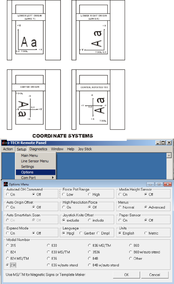
Coordinate System Allen Systems have four
origins to allow for flexibility when using various
CAD/CAS systems. The i-TECH is shipped with
the Long X coordinate system in all factory set-ups
and is compatible with most cutter or printer
drivers. The choice of coordinate systems other
than Long X is beyond the scope of this
document.
Options Menu
The options menu displays and sets the
following parameters:
Auto Origin Offset determines whether
moving the joystick automatically sets the
origin to (0,0). Most CAD systems and the
Allen DirectCut printer driver require this
option to be set On. Set to Off when cutting
from a CAD system that does not use the
SmartMark sensor such as the Gerber Omega
software. Pressing load key after joystick when
set to off will set origin manually to (0,0).
Media Height Sensor turns on or off the
load function that senses the width of the media
based on the set up of the pinch wheels. With this function enabled, the cutter head will scan a
magnet on the pinch wheels to establish the height of the media. With the function off, the cutter is
loaded with the maximum width. This option is normally set to Off.
23

Menus option offers the more advanced features of the software. It is recommended this be set
to Normal until a more advance feature is understood or is required by your operation. The menu
items below are displayed when the menus is set to Advanced.
Paper Sensor Some units come with paper sensors. This option allows turning the sensors on
and off. If off the cutter will assume there is always media in the cutter.
Units sets the units of measure to English or Metric units.
Model sets the model number. Password for model number change is 23. Do not change the
model number unless you know what you are doing.
Options menu (Advance Options)
Autocad OH Command determines how the system will respond to the HPGL OH command.
Set to off unless you are using a very old Autocad system that communicates directly to the cutter.
Auto SmartMark Scan if off no action is taken. This option was created for Gerber
language output direct from composer. It changes the IN hpgl command at beginning of job to
include an FO command. Set language to Gerber so the page advance at end of job works
correctly.
Expand Mode allows the cutter to cut past the normal clip limits in the Y-axis. This function
allows cutting and extra 1/2 inch (12 mm) wider.
Force Pot Range is used only on model 315 and 230. If set to low force pot range is 0-50%.
This allows higher resolution for low forces. If set to high force pot range is 0-100%. This must
be set to high if you need more than 250 grams of force.
High Resolution Force sets the force resolution to 1 to 1000 steps instead of 1 to 100 steps. It
is useful when cutting very hard to cut medias. It allow setting the force between two of the
standard force settings. A force of 112 is equivalent to 11.2 % force. (also see the Dynamic Force
Adjust (Advanced Option)).
Joystick Knife Offset this option controls whether the cutting data point includes or excludes
the knife offset. The normal setting is
exclude. Include is used for CadLink’s
SignCad program when digitizing only.
Language determines which language
the cutter uses. Select Hpgl for most cad
systems and the DirectCUT
TM
Printer
Driver. If you are using Gerber Omega
select Gerber. If your cad system only
output dmpl you can select this language.
Dynamic Force Adjust (Ad-
vanced Option)
This feature is considered an advanced
feature and does not appear on the Setup
menu unless the menu is set to advanced
on the option page. Dynamic Force allows different forces to be applied at different velocities.
Adjust sets up the dynamic force parameters and database. To establish a new material database
type in the name of the new material in the Material Selection box and click Add. In the Force
and Velocity Window, type in the desired force vs. velocity that you have established for the
24

material. The recommended method for establishing the various force vs. velocity numbers is to
run the test cut at various velocities and record the results for entry here.
Enter the Maximum cut speed for the media in the Max Draw Speed window.
Before using Dynamic Force Adjust, it is necessary to send the force setup to the cutter memory by
clicking the Send Force to Cutter button.
Com Port menu is used to set
the communications port to the
Remote Panel only. It does not
set the communications port for
the design software or Allen
DirectCut Driver. The Local
Echo mode is used in
communicating directly from the
remote panel while in Terminal
Mode. Select Lan if connected
via Ethernet.
Font Size sets the font size for
the Remote Panel Program.
Diagnostics
See the diagnostics section of this manual. Additional diagnostics are available if advanced menus
are used.
Window
In user operation only terminal mode is useful.
Some advance diagnostics use a chart to display data. This menu allows changing between chart
and terminal data.
Help
About display software version of remote panel. The firmware version of the cutter is displayed
on the main menu.
Putting a check next to enable debug log displays the communication lines between the cutter and
the remote panel. (This is an advanced option)
Putting a check next to enable character log display each character as it is sent / received to / from
the cutter and its direction. (This is an advanced option)
Clear log clears communication messages from the screen.
Joy Stick
JOYSTICK The joystick is used for positioning the
knife and media in the die cutting station.
The four ARROW KEYS are used to jog the material
or cutter carriage that holds the knife blade and the
SmartMark sensor. With the Jog/Slew box unchecked
so that Jog/Slew = Slew, the joystick speed will be the
25

speed set in the Joystick Speed Window. Left Click and hold the arrow button to move the
material or carriage. With the Jog/Slew box checked so that Jog/Slew = Jog, the arrow buttons will
jog the cutter that fixed distance each time the button is clicked.
The setting in the Jog Distance Window also sets the jog distance for the Front Panel Joystick
buttons.
Installing Knife Blades
Installing replacement blades
The knife blade should be replaced when the force has been increased by more than 20 percent or
the cut quality has degraded. The first sign of blade degradation usually occurs in the corners of
the cut and may lead to poor weeding.
New blades slide into the holder to a preset height and are held in magnetically. No tools or
adjustments are required. To replace the blade, first remove the blade holder from the tool holder
by loosening the brass thumbscrew and pulling up on the silver knife holder. Remove the black
plastic cap. To remove the used blade, grasp it with a pair of tweezers and pull it out of the knife
holder (discard the blade safely). Remove the new blade from the plastic case and remove the
protective cap. Insert the blade into the holder and let the magnet pull it into the preset position.
Put black cap back on knife holder. Reinsert the knife holder into the tool holder and tighten the
brass thumbscrew.
Replacement blades are available from Allen Datagraph Systems, LLC. They can be purchased
online @ http://www.allendatagraph.com/ or by calling 603-216-6344.
H20-017 30° Allen Datagraph i-TECH, DFS, Centra, Axxis cutting blade. Ideal for label stock.
Angle of blade at 30 degrees to have exact control on depth of cut. This blade has a 0.012 inch
(0.0305 cm) offset. It can be identified by its blue plastic cap.
H20-007 45° Allen Datagraph i-TECH, DFS, Centra, Axxis cutting blade. Ideal for general pur-
pose cutting of vinyl and other thin materials. Angle of blade at 45 degrees to balance depth of cut-
ting and pivot angle. This blade has a 0.012 inch (0.0305 cm) offset. It can be identified by its red
plastic cap.
H20-008 60° Allen Datagraph i-TECH, DFS, Centra, Axxis cutting blade. Ideal for cutting thick
materials. Angle of blade at 60 degrees to optimize cut angle. This blade has a 0.012 inch (0.0305
cm) offset. It can be identified by its green plastic cap.
Tool Holder Block
The knife blade holder is installed in the tool holder block with a thumbscrew. The tool holder
block is held to the cutting head by two hex drive screws.
Knife blade holder Assembly
The blade holder is designed for use with Allen Datagraph’s 30°, 45° and 60° blades. Solvents and
lubricants should not be used, as they will diminish cutting accuracy.
Knife Blades
Knifes blades for the Allen Datagraph i-TECH Unit are made with tungsten carbide and are
designed specifically for digital die cutting. The tip is offset from the center of the shaft so that the
blade has a caster action when pulled. Blades are available in 30, 45 and 60-degree tip angles. The
60-degree is intended only for thick materials such as sandblast mask or thick over-laminates. For
best cutting results, protect the knife tip from damage when not in use.
26

Knife Blades Depth Guide
Allen Datagraph's controlled depth knife holder has a depth guide that is adjustable to control the
depth of cut the cutter makes. Correct adjustments allow the blade to cut the material and lightly
mark the backer (carrier) material. Too much cut depth can cause cut through and premature blade
wear. Not enough cut depth will make "weeding" of media difficult.
Use the cut test, force and depth adjustment to establish good cutting (see setting cut force – cut
depth section)
Use the cut test and force to establish good cutting (see setting cut force – cut depth section)
Cut Strip
Clean any debris from the groove before installing a new cut strip. The strip simply snaps into and
out of place with no special tools required. It is important that the cut strip be installed fully
and evenly, otherwise material cut through may occur in some sections across the cutter. The
cut strip should be installed for knives and pen plotting, but must be removed for Pouncing.
Replacement cut strips are available at online store http://adsi-usa.com/. Select store and cutter
supplies to see available cut strips.
Calibration
Cutter calibration for SmartMark is beyond the scope of this document. Please read calibration
procedure Website Copy / CD Copy available on the technical support page of the Allen Datagraph
web site at http://www.allendatagraph.com. Standard cutter calibration is described in Appendix I
or Website Copy / CD Copy
Maintenance
Cleaning
The regularity with which the cutter needs to be cleaned is dependent on the usage, as well as the
climate and contaminants in the cutter’s environment. It is recommended that the following
cleaning steps be done at least as often as indicated for each procedure:
1. Biweekly. Clean the three grit wheel surfaces with a stiff bristled e.g. tooth (not wire)
brush to remove any media particles that may have built up during cutting. Brush the
surface of the grit wheel while turning the grit wheel by hand so the entire surface of
the grit wheel is cleaned. CAUTION: Be sure to disconnect the cutter from the power
source while cleaning the unit. Keeping the grit wheel clean is important so the cutter
will hold the media accurately.
2. Biweekly. Wipe media-related dust from the set of polyurethane pinch wheels by using
a soft cloth.
3. Monthly. The outer surfaces should also be kept clean. If necessary, a mild cleaning
solution on a damp cloth can be used to gently wipe the surfaces clean. It is suggested
that a mild soap and water be used with a soft cloth. This solution works well on all
painted surfaces. CAUTION: Do not use any abrasive cleaners, as they will cause the
paint to blister.
4. Yearly. Inspect the internal circuit board assemblies and clean accumulated dust as
necessary. Be certain that the cutter power is off. Observe static discharge safety
procedures that may damage sensitive electronic components. Wear a grounding strap
connected to earth ground. Wear safety glasses to protect eyes. Remove front and side
covers and use compressed air to remove dust and debris. Replace cover to original
location and make certain that that any connectors are well seated.
27

Pinch Wheel Maintenance
Pinch wheels are critical to the i-TECH unit's material handling performance. They should be
inspected for wear regularly and cleaned as needed. To clean adhesive off the pinch wheels, simply
use a soft cloth and denatured alcohol.
In normal use, the pinch wheels will need to be replaced in time. Also, trying to move them when
they are in the down position can damage them. If material does not track well and guide alignment
has been verified, the pinch wheels may need to be replaced. For best tracking results, replacement
pinch wheels should be replaced as a SET.
To check condition of pinch wheels:
1) Inspect condition of rubber The rubber wheel should not have any cracks and should be
securely adhered to the aluminum hub of the wheel. The transition from the flat surface of the
wheel to the "sidewall" edges of the wheel should be sharp and not rounded.
2) Inspect integrity of pinch wheel bearing This is done by having the pinch wheels in the up
position. Spin wheel with finger and observe whether the bearing has a dry sound or not. If it
appears to be dry, the wheels should be replaced.
Mechanical Adjustments
Belt Tension
The i-TECH servomotors use timing belts to control the material (X axis) and tool (Y axis)
positions. The belt tension and wear should be inspected if cut quality deteriorates. To inspect the
belts, remove the pods at either end of the i-TECH. This can be done by removing about 16 screws
along the edge of the pod covers. You can operate the cutter with pods installed in the extended
position by reinstalling the pods using two screws. (see also TSB: Mechanical Adjustments to
Restore Cut Quality Website Copy / CD Copy)
Y-Axis
The Y-axis short belt runs between the Y-axis servomotor and a gear assembly under the left hand
pod. To adjust the tension of this belt, it is necessary to reposition the motor bracket.
1. Loosen the three Phillips head motor bracket screws and apply hand pressure to
tighten the belt so that the belt will deflect 0.050 inches at the center when 23
ounces are applied. (1.3 mm when 660 grams are applied).
2. When the belt is tight and the motor shaft is parallel to the bearing shaft, tighten
the three Phillips head motor bracket screws. Premature belt failure will occur if
these two shafts are not parallel.
3. Verify tension.
The long belt is adjusted using a lead screw located behind the control panel. To set the long belt's
tension:
1. Position the carriage to about 24 inches from one end.
2. Remove the control panel housing as follows
a. Install the right pod at extended position as described above.
b. Remove the top rail cover over the carriage by removing the two screws at
each end of the cover.
3. Loosen locking nut. Adjust the lead screw so that the 24" of belt when plucked like a
guitar string vibrates at a low base note. It should not flop around and stop oscillating
immediately.
4. Set the lead screw lock nut.
28
5. Verify belt path and tension.
6. Replace the control panel housing, top rail cover and rear cover.
X-Axis
The belt inside the rear cover drives the grit wheel (X axis). To adjust the tension of this belt, it is
necessary to reposition the motor.
1. Loosen the two motor bracket screws and apply hand pressure to tighten the belt so
that the belt will deflect 1/16 inch at the center when 23 ounces are applied. (2 mm
when 660 grams are applied). (Replace belt if damaged or worn).
2. When the belt is correctly tensioned, tighten the two motor bracket screws.
3. Verify belt path and tension. Check that the large gear turns freely.
Diagnostics
The i-TECH CUTTER firmware contains a set of resident diagnostics. When the i-TECH
CUTTER is powered up, it automatically performs a self-test program to check all operating
parameters. If a malfunction is detected, the letter “E” and a three-digit error number will be
displayed in the display window. The error numbers and the corresponding malfunction
descriptions are given in the Error Codes section. When an error is displayed and no obvious
damage was done to the cutter, power off the cutter and repeat the procedure that caused the error
display. If the error reoccurs, the user may push any key on the control panel to enter the diagnostic
mode. Many errors automatically place the cutter in the diagnostic mode when a key is pressed.
The fail-safe system is designed to detect failures in the operation of the electromechanical system
in the cutter and to prevent such failures from causing other damage. The cutter monitors motor
currents and will generate an error if motor current too high or unmeasureable. It also generates an
error for impossible or dangerous conditions. The appropriate error code will appear, as mentioned
above, in the display window on the control panel.
Diagnostic Operation
The diagnostics in the i-TECH Cutter exist at several levels:
a. POWER-ON
b. CONTINUOUS HARDWARE AND SOFTWARE MONITORING
c. OFF-LINE
The POWER-ON diagnostics are performed at power-on or reset of the microprocessor and test the
microprocessor, memory, servo analog and digital hardware, and some of the testable sensors.
After initialization, continuous hardware and software check the sensors and fail-safe monitors for
machine malfunctions. If a malfunction is detected, an error code is displayed on the control panel
display, the protection relay is opened, and the cutter ceases operation.
Control panel operation
Starting the diagnostics from Control Panel
Turn unit on and allow initialization to complete. If the i-TECH Cutter is displaying a flashing
error code on the front panel display, press any key to enter the diagnostic mode.
Press the select key to initiate the menu function, Press the left or right arrow key to display diA.
Press the up or down key to scroll thru the diagnostic numbers (0002 – 0099). Press the select key
to start the diagnostic.
29

To Stop a Diagnostic
Press the reset key sequence F1, F2,
F3 or power off and on unit.
To Exit the Diagnostic
Mode
To return to normal operation, run
diagnostic 99 or cycle the cutter power
off and on.
Remote panel operation
Certain diagnostics are easier to run
from the remote panel. To run the
customer diagnostics from the remote
panel program:
Open the remote panel
Open the Diagnostics Menu
IMPORTANT!! DO NOT run Manufacturing Diagnostics unless specifically instructed by
direct contact with Allen Datagraph Technical support. Damage to the system is possible if
not run correctly.
Setup Diagnostics
Calibrate 07, Calibrate To Printer and SmartMark Setup
have been described in other sections of this document or the SmartMark Setup Document or the
template maker supplement Appendix I or Website Copy / CD Copy
Calibration Square Plot
prompts for a square size and sends an HPGL command to output the square. This is useful when
calibrating the cutter to a ruler rather than a printer and is normally not required. Specifying 10
inches for the size will send the HPGL commands to draw a 10 inch square.
Default Calibration 08
diagnostic sets the calibration constants back to the factory defaults prior to initial calibration. Af-
ter running this diagnostic you will have to either restore the calibration constants or rerun the cali-
bration procedure described in Website Copy / CD Copy available on the technical support page of
the Allen Datagraph web site at http://www.allendatagraph.com. As this is a rather involved pro-
cedure Diagnostic 08 should be avoided unless you have received an E37 error, which automatical-
ly runs this diagnostic.
FO Output
command sends the <esc>.vfooutput;1: command which displays software debug information
about the last FO command. The first line output indicates the location of the three targets and
whether they were found. The last two lines indicate the amount of scaling and rotation calculated
that need to be applied to the HPGL commands to cut the image.
It normally is not useful for customers to run this diagnostic. Information displayed is recorded in
the serial.log file.
Customer Diagnostics
The rest of the diagnostics do not appear on the menu until advanced menus are selected from the
setup -> options menu. The “Customer Diagnostics” are designed for use by the customer to aid in
trouble shooting the i-TECH cutter..
30

To run a customer diagnostic, click on the menu item and the diagnostic will automatically start.
Some require intervention after starting and you will be given instructions on the screen. The num-
ber pad on your computer keyboard is mapped to simulate buttons on the front panel of the cutter.
The mapping is displayed on the screen. Make sure window is wide enough so the wrapping of
text is not done by the software or it will be hard to read.
Button Diagnostic 31
Test the operation of each of the buttons on the front panel. Buttons must be pressed in the
following order: Load, Pause, Copy, Speed Up, Speed Down, Force Up, Force Down, Test Cut, F3,
F2, F1, Select, Left, Right, Up, Down. If the wrong code is received the error code E036 is
displayed otherwise the requested button is requested with the button name prompt.
Confidence Test 02
The confidence test is used to verify the operation of the cutting station of the i-TECH. It fully
tests the capability of the cutting CPU and Servo control system.
To run the confidence test the cutter must be unloaded. If the load led is on press pause and load in
sequence of the front panel to unload machine. Install a piece of paper (designed for d size but will
work on any size by scaling the test to size of media). Left and right pinch wheels should be on the
edge of the media. The media should hang out the back of the machine with the front edge near the
cut strip. Install a pen in the cutter. Start diagnostic. The media width will be measured and the
size of the media will be assumed to be proportional to the width measured. A test pattern will
then be plotted.
With 230/315 front panel press copy, copy, test cut to start confidence test.
With membrane panel: from the front panel scroll to 0002 press the Select Key. The i-TECH
will start by sensing the media width and then will draw a sample file.
From the remote panel click on Confidence Test 02. The i-TECH will start by sensing the
media width and then will draw a sample file.
Flag Adjust 34
This diagnostic is used to verify the correct flag position on the cutting head. It displays the knife
height on the display. The flag is a small, flat, angled piece of metal which moves up and down
between a pair of circuit board mounted sensors. The flag is held on to the knife holder by 2 Allen
screws, which are loosened slightly if adjustment is necessary. There are 3 locations the knife
holder can be in. They are:
Bottom (remove the knife from the holder and press the holder down to the bottom) The display
should read between 000 and 006.
Down (press the knife down with a knife in the holder) The display should read 020 to 030
pressing down with a knife in the holder (no media present). Adjust flag position if necessary.
Top (hold the knife up) The display should read 0100 or more.
The display should change immediately as you move the knife up or down away from top or
bottom positions.
Slightly move the flag to obtain the above reading at each of the three locations.
Check that the flag screws are tight and recheck Bottom and Down.
To start the diagnostic
From the front panel scroll to 0034 and press the Select Key.
From the remote panel click on Flag Position 34.
31
Flag Setup - Z Axis 58
It is necessary to run Diagnostic 34 to verify carriage flag setting before performing this
diagnostic. This diagnostic configures the carriage to the cutter. It measures the up, down, and
bottom position of the knife so that it can properly raise and lower the knife without punching a
hole in the media.
From the Front Panel scroll to 0058 then press the Select Key.
From the Remote Panel click on Flag Setup 58.
After starting a phase is display on the display of the cutter or under the word DISPLAY on the re-
mote panel.
Phase 4: Set Tool Bottom - Remove the tool from the holder and press the Select Key.
Phase 5: Set Tool Down - Adjust knife depth guide to equal the blade length. Place knife tool in
holder. Press the Select Key.
Phase 6 and 7 displayed on models 315 and 230 align the printing for the numbers on the force and
velocity pots to values received.
Phase 6: set force and velocity pots to 1 then press select key (5 key on computer keyboard)
Phase 7: set force and velocity pots to 100 then press select key (5 key on computer keyboard)
Power Down Cutter to continue.
Front Paper Sensor 26 / Rear Paper Sensor 27
Some units are configured with media present sensors. They detect the presence of media. If they
detect media a 1111 is displayed on the front panel. If they do not detect media 0000 is display. If
your cutter has paper sensors they will be mounted just below the oval holes in the platen on the
right side of the cutter. The paper dust must be removed from windows of sensors in order for sen-
sor to work correctly.
LED and Hex Display 29
Exercises the LEDS and the 4-character display.
Line Sensor 21
Continuously displays the result of the SmartMark Line sensor. When you place a white piece
of material under sensor a number > 100 should be displayed. When you place a printer black tar-
get under sensor the reading should be < 20.
Lift/Lower Continuous 37
Exercises the z axis lift lower at different forces. Continuously raises and lowers the knife.
Lift/Lower Demand 38
Exercises the z axis lift lower at different forces. Raises and lowers the knife on each select key
press. While knife is down at a force the cutter displays the current through the voice coil and the
width of the pwm pulse to the z axis driver.
PWM Amplifier Status
This displays the power amplifier temperatures if the PWM power amplifier.
Read Calibration Constants
Reads and displays the scaling constants for the x and y axes. Safe to run. X and Y encoder counts
are dependent on model number.
32
Reed Switch 24
This diagnostic continuously displays the result of the media height sensor. As the reed switch
passes in front of a pinch wheel with a magnet installed, the output will change from 1111 to 0000.
Front Panel Only Diagnostics
Some diagnostics can only be run from the front panel
Display Last Error 15
Running diagnostic 15 will display the last error number saved in NVM.
Factory Defaults 43
You can select factory defaults for settings by running diagnostic 43.
Set Model Number 03
From the control panel scroll to 0003 and press the select key. Enter password of 23 and then
select. Enter model press the Select Key. Do not change the model number unless you know what
you are doing.
From the remote panel open the Set-up menu then the Options Menu. Click on the desired
Model Radio Button. When you click on OK the remote panel will ask for the password to change
the model number. Enter password 23 and click on ok.
Set Static/DHCP IP Address 04
Normally you do not need to run this diagnostic. If you are using a cross over cable the default ad-
dress is 192.168.4.10 and you have set your computers ip address to 192.168.4.2. If you are using
a dhcp server, most algorithms normally try to assign same ip address to mac address everytime the
device requests an ip address. If you have trouble with your dhcp server giving you a different ip
address everytime you turn on your machine you can set a static ip address.
To run diagnostic on 230 or 315 you type esc.z (e.g. press esc key, then period key then z key) to
open simulated front panel, start diagnostic by pressing keys on numeric pad as if you were press-
ing them on front panel of cutter.
To change the default IP address for mmc you run diagnostic 4 on the mmc.
Select -> right arrow to dia -> up arrow to 0004 -> select
if dhcp is desired select dhcp and press select.
Otherwise if you want to set your cutter to use ip address 192.168.4.10 and mask to 255.255.255.0
and gateway of 192.168.4.1 use up/down to select IP then press select key
Change first part of address with force/speed up/down key to 192 then press select
change 2nd part of ip address to 168 then press select
change 3rd part of ip address to 4 then press select
change 4th part of ip address to 10 then press select
MAS will then appear. Press select
First part of mask is 255 -> press select
2nd part of mask is 255 -> press select
change 3rd part of mask to 255 then press select
4th part of mask is 0 -> press select
33

gAtE will appear. Press select
change 1st part of gateway to 192 then press select
change 2nd part of gateway to 168 then press select
change 3rd part of gateway to 4 then press select
change 4th part of gateway to 1 then press select.
Trouble Shooting
Problem Solutions
Cutter does nothing
Panel lights off, no fan noise : plugged in, power on, cycle
power
On Hot tip units check fuse in power entry module. Replace
with one 5A fuse for 115 vac or two 2.5A fuses for 220 vac.
Cut through/poor weeding
Is your knife blade sharp? You can check condition of blade by
examining the blade tip under a 30x microscope. The blade tip
must be present.
For very thin (less than 0.002 inch, (0.05 mm)) or liner less than
20 lb. media you might need to use the controlled depth
adjustment on the end of the knife holder. Partially unscrew the
black cap until just enough knife blade is exposed to cut through
the media but not the backer. Test by drawing knife across
media by hand. You can then use a higher force with no cut
through.
It is important that the groove filler be installed fully and evenly,
otherwise material cut through may occur in some sections
across the cutter.
Insufficient backer weight.
Check mechanical adjustments Website Copy / CD Copy
Increase / Decrease force. Increase decrease knife offset.
Check cut strip condition. Replace or reverse if damaged.
Decrease acceleration or speed.
Increase resolution in printer driver.
Do not allow cutter motors to pull media off of roll.
Using wrong angle of blade for material.
Images are incorrect size
If error is small (< 1/2 inch (12 mm)) make sure grit wheel is
clean. Dirt build up in grit will change the size of the grit wheel
making it cut the wrong size. Run diagnostic 07 to calibrate the
cutter to a ruler.
If error is large (10% or more) then you probably have wrong
model number in cutter or mismatched AllenCad and printer
34

driver versions. Model numbers for template maker and
Magnetic sign cutters are in the 2000 range. GT cutters do not
have 2000 added to model number. Check the model number
displayed on the remote panel setup -> main menu.
Template cuts off by small amounts or different amounts each
time. Website Copy / CD Copy
Contour cuts are wrong
size.
If you are using origin only or origin skew no scaling is done to
image received. In this case you must calibrate the cutter to
your printer rather than a ruler. You do this by printing a large
rectangle on your printer. Then cut the same size rectangle. For
x and y drawn use printed size rather than a ruler as drawn or
desired size.
If you are using origin scale, or origin skew scale then the size of
the cut is change by the x or y sensor size parameter in the line
sensor menu. See Smart Mark Setup section.
Labels or contour cuts are
cutting in the wrong spot
Verify you created job correctly.
Origin target is at minimum x and maximum y of drawing.
The scan area contains only target and background with no stray
marks that could be seen as targets.
Verify printer properties are correct
Rotation is set correctly. Target cut should be in same corner on
preview as selected origin corner.
Find origin property is set to Origin only or other advanced op-
tion.
Verify sensor settings have not been lost in the remote panel se-
lect setup -> line sensor menu.
Verify x sensor offset is about 0.75 inch and y sensor offset is
about –0.1 inch
If your job is off by only a little bit (less than 1/8 inch (3mm))
and is same for every frame you can measure this error and cor-
rect your x and y sensor offset by the amount of the error you
measure.
Verify scan length is the same as the length of the side of the tar-
get
Verify the scan offsets = ½ of the length of the side of the target
Verify the Scan Velocity is either 1 or 2.
Verify the space between jobs in the line sensor menu is zero.
Verify Skew target is at minimum x, maximum y of artwork.
Verify Scale target is at maximum x, minimum y of artwork.
Target errors tar1, tar2,
tar3, tar4
These errors indicate that the target scanner did not find the tar-
get.
If tar1 on first frame:
o Verify that you positioned red led pointer to right rear
corner of target
35

o Verify red led is lit.
o Check that distance led is from media is 3.4 to 4.6 mm.
o Run line sensor diagnostic (21) to verify operation of
sensor.
If tar1 on 2
nd
or subsequent frame
o Verify space between jobs in printer driver is set cor-
rectly. If it is set correctly after cutting first frame the
knife blade should be on the right rear corner of target of
next frame.
Tar2 – 4.
o Verify job you are sending matches job you printed
o Verify rotation is correct in printer driver
o Verify job is built correctly in that scale and skew target
print is in same location is die lines for scale and skew
target.
o Verify scale and skew targets are at extents of image.
Skew should be a minimum x and maximum y. Scale
target should be at maximum x and minimum y.
Composer spools out lots
of material before cutting
image
When using direct cut driver and sending from Gerber software,
if the cutter spools out lots of material instead of cutting where it
is, go to file, print, select Allen device, click options tab,
uncheck HEADER box, click preferences button.
No action when you send
data to cutter
Allen Spooler: If plot is sent from computer and cutter doesn’t
cut, check for Allen spooler in the task bar (Lower right of
monitor, green box with red arrow, near time). If it is not there,
go to start button, programs (all programs), startup, allen spooler
and click on allen spooler. If you get message saying allen
spooler starting with one job left in queue, cancel it and send job
again after checking to see that cutter is ready.
Click on red arrow in green field icon in service icon area. If
you are getting unable to open port displayed
See if remote panel still has port open. It should auto close the
port after 5 seconds.
Reboot computer and cutter.
Verify port selected is correct. You can find the correct port
from the device manager.
Plug usb cable into same usb port as you normally do. Different
usb holes are normally configured as different com ports.
Rerun enable printer driver to find cutter. Start > All Programs
> Allen Datagraph > Cutter Driver > Enable printer driver
Try different usb cable or different computer.
From spooler cancel all jobs, turn cutter off/on and resend job.
No usb driver installed for equipment Website Copy / CD Copy
36

Cutter in pause state.
Job does not complete
Verify minimum cutter driver level of 2.08g. New software can
be downloaded from Web Site Copy
If you have less the firmware revision 12 as usb version in your
cutter turn off polyline encoded output in printer properties, de-
vice settings. Web Site Copy / CD Copy
Try a different cable or computer
When I turn my cutter on,
the head reaches the side
plate and makes a loud
noise
Loose long Y belt
if carriage is getting to the right side and making a ratcheting
noise, it's could be the long y axis belt, or the y axis motor belt
located under the left control panel. To determine which belt it
is, turn the machine on while holding out on the long belt that at-
taches to the cutting head. What this does is put more tension on
the belt. If the head gets to the side and they don't hear the noise,
proceed to below:
Remove the control panel and locate the belt tensioner. This is a
wedge-shaped device with a long Phillips head screw protruding
toward the rear of the machine.
Loosen the 3/8" locking nut holding the tensioner screw in place.
Turn the phillips screw a couple turns clockwise, then turn the
cutter on before attaching the control panel. If the cutter initial-
izes, there is no need to look further. If this does not solve the
problem, proceed to the next step:
Open rear cover, turn cutter on and observe the belt attached to
the motor. If the motor pulley continues to turn, then the short
motor belt is most likely either loose or worn out. Carefully in-
spect the teeth on the belt for wear with the machine off. The
pulley can be rotated to allow inspection of teeth.
If the teeth are not worn or stripped off the belt, loosen the three
mounting screws holding the motor bracket to the sideplate.
Apply tension to the motor bracket BY HAND, and tighten the
screws. The belt should have less than 1/8” of free play when
properly tightened.
Media sensors can’t see
black EC film or vinyl
with clear backer.
Turn off paper sensors using setup -> options in remote panel.
Cover 1/2 the sensor hole with masking tape.
Router keeps changing
my ip address
Some routers do not keep a table of mac addresses so that the
same computer will be assigned same ip address each time you
power up. In this case run diagnostic 4 and assign a static ip ad-
dress to the cutter. See also Website Copy / CD Copy
Material Does not track
straight
Tracking video Website Copy / CD Copy
Instructions for adjusting donuts on tracking guides Website
Copy / CD Copy
Move pinch wheels out of punched area.
Do not allow cutter to pull media off of roll.
37

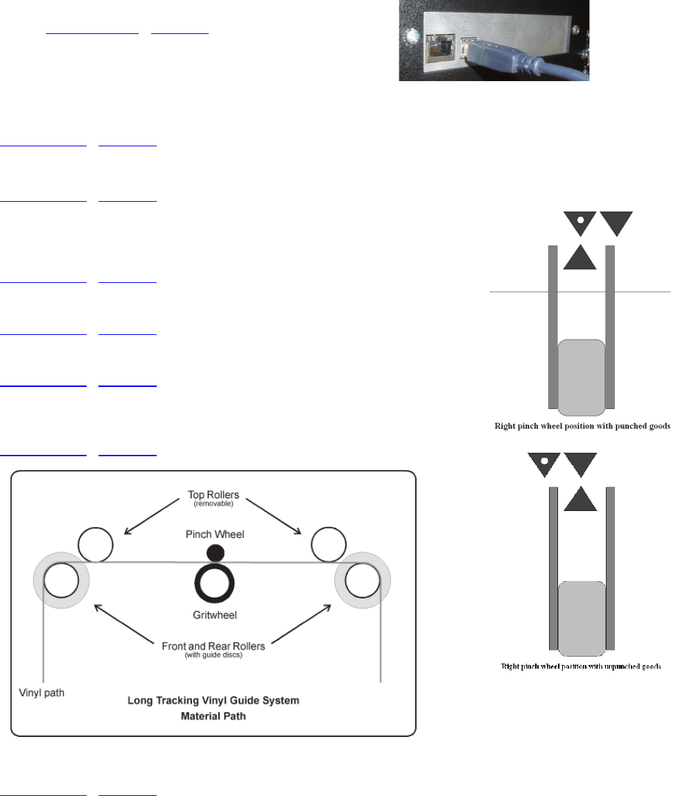
Error Codes
If the internal microprocessor detects an error condition, the letter E0 and a 2 digit code will be
displayed on the control panel. Any key pressed after the error is displayed will place the machine
in the diagnostic mode, indicated by a flashing "D" on the control panel. Recommended diagnostic
procedures (D##) are listed in the error description.
The mmc software error codes are in the following linked doc-
ument. Web Site Copy / CD Copy. You can recognize the
mmc machines by looking at the communication port. If your
port looks like this use this link to error codes.
Appendix A Installation And Assembly Instructions
Website Copy / CD Copy
Appendix B SmartMark
TM
Setup
Website Copy / CD Copy
Appendix C Loading
Model 230
Website Copy / CD Copy
Model 315
Website Copy / CD Copy
Model 536
Website Copy / CD Copy
Model 824, 824 ms, 824 tm, 830, 830ms, 830tm, 836, 836ms, 836tm, 848,
860
Website Copy / CD Copy
Appendix D Cart Assembly Instructions
Website Copy / CD Copy
39

Appendix E Radio and Television Interference
NOTE: This equipment has been tested and found to comply with the limits for a Class A digital
device, pursuant to Part 15 of the FCC rules. These limits are designed to provide reasonable pro-
tection against harmful interference when the equipment is operated in a commercial environment.
This equipment generates, uses and can radiate radio frequency energy and, if not installed and
used in accordance with the instruction manual, may cause harmful interference to radio communi-
cations. Operation of this equipment in a residential area is likely to cause harmful interference in
which case the user will be required to correct the interference at his own expense.
In order to maintain compliance with FCC regulations shielded cables must be used with this
equipment. Operation with non-approved equipment or unshielded cables is likely to result in in-
terference to radio & television reception.
This device complies with part 15 of FCC Rules. Operation is subject to the following two
conditions; (1) This device may not cause harmful interference, and (2) this device must accept any
interference received, including interference that may cause undesired operation.
Appendix F Model i-536 Addendum
Website Copy / CD Copy
Appendix G Model i-536 Adjustable Parameters
Website Copy / CD Copy
Appendix H Hot Tip Instructions
Website Copy / CD Copy
Appendix I Template Maker Supplement
Website Copy / CD Copy
40
